Hinging Control Surfaces
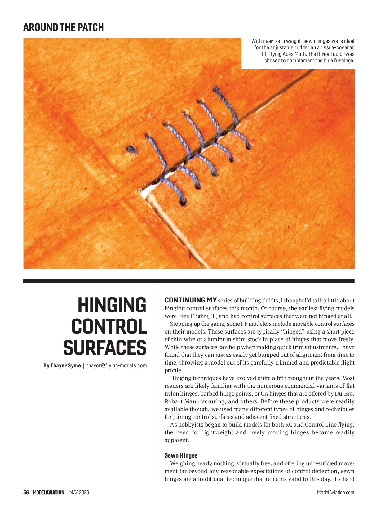
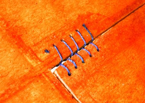
With near-zero weight, sewn hinges were ideal for the adjustable rudder on a tissue-covered FF Flying Aces Moth. The thread color was chosen to complement the blue fuselage.
Continuing my series of building tidbits, I thought I’d talk a little about hinging control surfaces this month. Of course, the earliest flying models were Free Flight (FF) and had control surfaces that were not hinged at all.
Stepping up the game, some FF modelers include movable control surfaces on their models. These surfaces are typically “hinged” using a short piece of thin wire or aluminum shim stock in place of hinges that move freely. While these surfaces can help when making quick trim adjustments, I have found that they can just as easily get bumped out of alignment from time to time, throwing a model out of its carefully trimmed and predictable flight profile.
Hinging techniques have evolved quite a bit throughout the years. Most readers are likely familiar with the numerous commercial variants of flat nylon hinges, barbed hinge points, or CA hinges that are offered by Du-Bro, Robart Manufacturing, and others. Before these products were readily available though, we used many different types of hinges and techniques for joining control surfaces and adjacent fixed structures.
As hobbyists began to build models for both RC and Control Line flying, the need for lightweight and freely moving hinges became readily apparent.
Sewn Hinges
Weighing nearly nothing, virtually free, and offering unrestricted movement far beyond any reasonable expectations of control deflection, sewn hinges are a traditional technique that remains valid to this day. It’s hard to argue with that list of characteristics, and once you learn a couple of tricks for installing them, they often remain the right choice.
As you can see, they are made simply by stitching the control surface and fixed structure together with a simple figure-eight stitch pattern. When I use them on one of my models, I carefully lay out a series of holes in the structure to ensure a consistent and clean appearance when it’s finished.
Use as small of a needle as possible to prevent the final holes from being too large. I find that they do close back up on their own as the wood relaxes. I also tie a knot on the end of the thread before I begin and pull that into the control surface with a drop of glue to secure the starting end of the thread.
Work back and forth between the surfaces, making sure to always pass the thread through the surfaces from the same direction. I come up from the bottom when I’m hinging the elevator to hide the start on the underside.
I use heavy button thread when possible and have also used a double strand of lighter weight thread in a pinch. When you get to the end of each hinge sequence, loop the thread back down through the final hole and again secure it with a small knot and drop of glue on the underside. I would caution against using thin CA around sewn hinges, though, because the adhesive’s capillary action can cause it to wick deeply into the thread and stiffen the hinges. Medium or thick CA can be applied with a toothpick and used to anchor the ends.
Once you try them, you will likely find yourself coming back to sewn hinges more often than you might have initially expected. The figure-eight sewing pattern will allow you to fold two flat surfaces back on each other, yet the hinge line remains nearly gap free.


Tabbed Hinges
A number of people who have seen my new 65-inch Drake flying boat in person have noticed the unique custom control-surface hinging and have asked how I set it up.
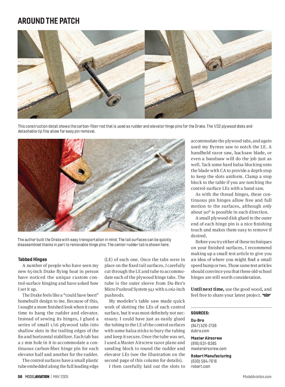
The Drake feels like a “could have been” homebuilt design to me. Because of this, I sought a more finished look when it came time to hang the rudder and elevator. Instead of sewing its hinges, I glued a series of small 1/16 plywood tabs into shallow slots in the trailing edges of the fin and horizontal stabilizer. Each tab has a 2 mm hole in it to accommodate a continuous carbon-fiber hinge pin for each elevator half and another for the rudder.
The control surfaces have a small plastic tube embedded along the full leading edge (LE) of each one. Once the tabs were in place on the fixed tail surfaces, I carefully cut through the LE and tube to accommodate each of the plywood hinge tabs. The tube is the outer sleeve from Du-Bro’s Micro Pushrod System 941 with 0.062-inch pushrods.
My modeler’s table saw made quick work of slotting the LEs of each control surface, but it was most definitely not necessary. I could have just as easily glued the tubing to the LE of the control surfaces with some balsa sticks to bury the tubing and keep it secure. Once the tube was set, I used a Master Airscrew razor plane and sanding block to round the rudder and elevator LEs (see the illustration on the second page of this column for details).
I then carefully laid out the slots to accommodate the plywood tabs, and again used my Byrnes saw to notch the LE. A handheld razor saw, hacksaw blade, or even a bandsaw will do the job just as well. Tack some hard balsa blocking onto the blade with CA to provide a depth stop to keep the slots uniform. Clamp a stop block to the table if you are notching the control-surface LEs with a band saw.
As with the thread hinges, these continuous pin hinges allow free and full motion to the surfaces, although only about 90° is possible in each direction.
A small plywood disk glued to the outer end of each hinge pin is a nice finishing touch and makes them easy to remove if desired.
Before you try either of these techniques on your finished surfaces, I recommend making up a small test article to give you an idea of where you might find a small speed bump or two. Those same test articles should convince you that these old-school hinges are still worth consideration.
Until next time, use the good wood, and feel free to share your latest project.


SOURCES
- Du-Bro
(847) 526-2136 - dubro.com
- Master Airscrew
(916) 631-8385 - masterairscrew.com
- Robart Manufacturing
(630) 584-7616 - robart.com