Joining Identical Fuselage Sides
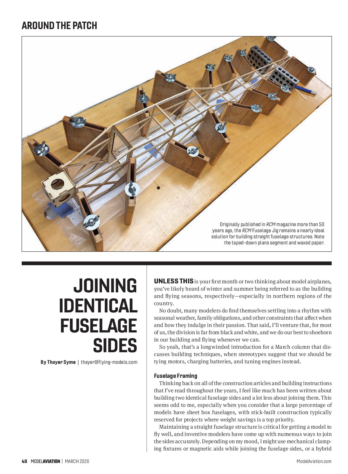
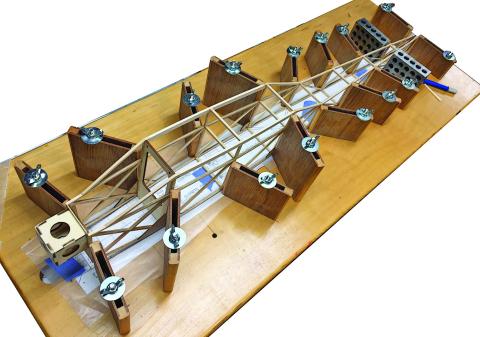
Originally published in RCM magazine more than 50 years ago, the RCM Fuselage Jig remains a nearly ideal solution for building straight fuselage structures. Note the taped-down plans segment and waxed paper.
Unless this is your first month or two thinking about model airplanes, you’ve likely heard of winter and summer being referred to as the building and flying seasons, respectively—especially in northern regions of the country.
No doubt, many modelers do find themselves settling into a rhythm with seasonal weather, family obligations, and other constraints that affect when and how they indulge in their passion. That said, I’ll venture that, for most of us, the division is far from black and white, and we do our best to shoehorn in our building and flying whenever we can.
So yeah, that’s a longwinded introduction for a March column that discusses building techniques, when stereotypes suggest that we should be tying motors, charging batteries, and tuning engines instead.
Fuselage Framing
Thinking back on all of the construction articles and building instructions that I’ve read throughout the years, I feel like much has been written about building two identical fuselage sides and a lot less about joining them. This seems odd to me, especially when you consider that a large percentage of models have sheet box fuselages, with stick-built construction typically reserved for projects where weight savings is a top priority.
Maintaining a straight fuselage structure is critical for getting a model to fly well, and inventive modelers have come up with numerous ways to join the sides accurately. Depending on my mood, I might use mechanical clamping fixtures or magnetic aids while joining the fuselage sides, or a hybrid combination of both. It really doesn’t matter which you prefer, as long as you maintain accuracy with both vertical and centerline alignment.
I won’t have space to cover all of the options in one column, so I will concentrate on one of my favorites for now. This is a timeless solution, and far from an original idea. It is just my twist (hopefully not!) on what came before me.
The mechanical clamping system that is shown is based on a 1972 article by W.A. Thienes, published in the now-defunct Radio Control Modeler magazine. Known simply as the RCM Fuselage Jig, it has been a reliable solution for countless thousands of modelers who have taken the time to build their own over the last 50-plus years. It has been nearly 30 years since I built my version, and it is still going strong with no signs of retiring any time soon. It is much more secure than my magnetic fixtures, but at the same time, it’s somewhat slower to set up, less flexible, and more awkward to store when it’s not in use. Yes, all systems have their pros and cons.
A quick internet search will reveal the original article and plans online, although, truthfully, much of what you need to know is shown here. A fistful of carriage bolts, washers, and wing nuts hold uprights—shop-made from thin plywood and wood strips—to a flat base. I milled a centerline on my base for reference, although even that is optional. Mine is often covered by a copy of the plans for my current project, as you can see here.
There are several key points to the design and use of the RCM Fuselage Jig that I offer based on my experience throughout the years. The most obvious is that I cut my uprights to three different heights: 2 inches, 3 inches, and 4 inches. The primary reason is that taller uprights can get in the way as you work on the aft fuselage, which is typically lower in profile.
I made my uprights by gluing up two larger assemblies of doorskin plywood and strips of pine. The pine was first milled with two small recesses to help consistently locate the plywood side panels. Cut these recesses slightly deeper than the plywood thickness, but be sure to leave enough thickness in the center to clear the 1/4-inch carriage bolts. This will minimize the risk of sanding through the face veneer after the glue-up and will still let the uprights move freely when the wing nuts are loosened.
Once everything dried, I rounded the protruding pine edges. This reduced the chance of denting the balsa structure when it was clamped. It is easiest to do this before cutting the individual pieces, and a router and roundover bit will do the job quickly if you have such luxuries. A hand plane will be quieter and not throw sawdust about your shop. A couple of coats of water-based polyurethane provided a nice finish.
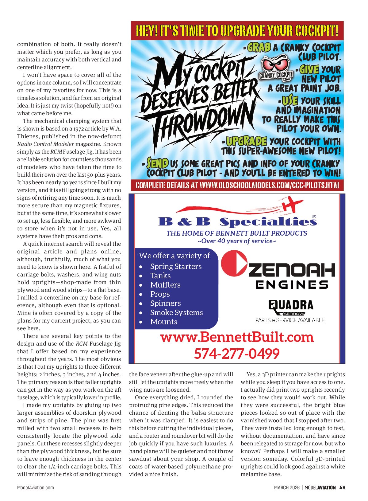
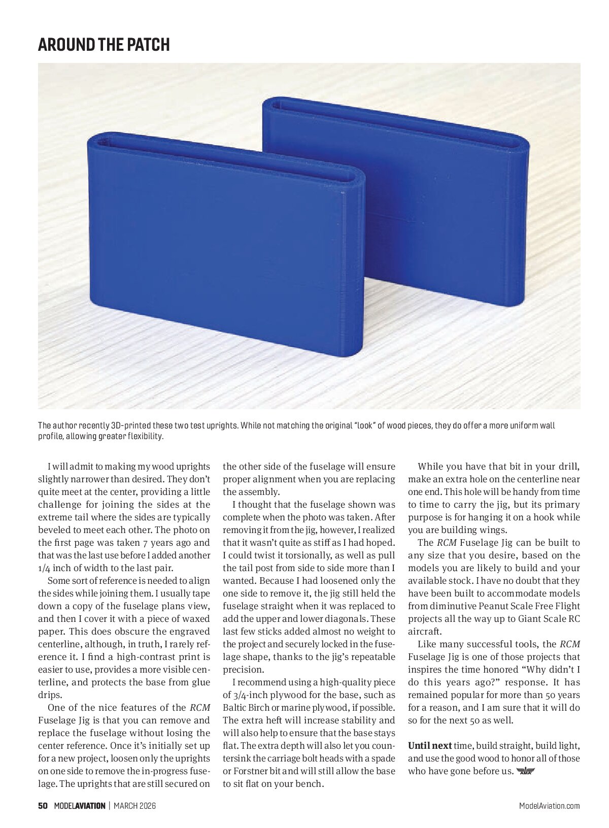
Yes, a 3D printer can make the uprights while you sleep if you have access to one. I actually did print two uprights recently to see how they would work out. While they were successful, the bright blue pieces looked so out of place with the varnished wood that I stopped after two. They were installed long enough to test, without documentation, and have since been relegated to storage for now, but who knows? Perhaps I will make a smaller version someday. Colorful 3D-printed uprights could look good against a white melamine base.
I will admit to making my wood uprights slightly narrower than desired. They don’t quite meet at the center, providing a little challenge for joining the sides at the extreme tail where the sides are typically beveled to meet each other. The photo on the first page was taken 7 years ago and that was the last use before I added another 1/4 inch of width to the last pair.
Some sort of reference is needed to align the sides while joining them. I usually tape down a copy of the fuselage plans view, and then I cover it with a piece of waxed paper. This does obscure the engraved centerline, although, in truth, I rarely reference it. I find a high-contrast print is easier to use, provides a more visible centerline, and protects the base from glue drips.
One of the nice features of the RCM Fuselage Jig is that you can remove and replace the fuselage without losing the center reference. Once it’s initially set up for a new project, loosen only the uprights on one side to remove the in-progress fuselage. The uprights that are still secured on the other side of the fuselage will ensure proper alignment when you are replacing the assembly.
I thought that the fuselage shown was complete when the photo was taken. After removing it from the jig, however, I realized that it wasn’t quite as stiff as I had hoped. I could twist it torsionally, as well as pull the tail post from side to side more than I wanted. Because I had loosened only the one side to remove it, the jig still held the fuselage straight when it was replaced to add the upper and lower diagonals. These last few sticks added almost no weight to the project and securely locked in the fuselage shape, thanks to the jig’s repeatable precision.
I recommend using a high-quality piece of 3/4-inch plywood for the base, such as Baltic Birch or marine plywood, if possible. The extra heft will increase stability and will also help to ensure that the base stays flat. The extra depth will also let you countersink the carriage bolt heads with a spade or Forstner bit and will still allow the base to sit flat on your bench.
While you have that bit in your drill, make an extra hole on the centerline near one end. This hole will be handy from time to time to carry the jig, but its primary purpose is for hanging it on a hook while you are building wings.
The RCM Fuselage Jig can be built to any size that you desire, based on the models you are likely to build and your available stock. I have no doubt that they have been built to accommodate models from diminutive Peanut Scale Free Flight projects all the way up to Giant Scale RC aircraft.
Like many successful tools, the RCM Fuselage Jig is one of those projects that inspires the time honored “Why didn’t I do this years ago?” response. It has remained popular for more than 50 years for a reason, and I am sure that it will do so for the next 50 as well.
Until next time, build straight, build light, and use the good wood to honor all of those who have gone before us.