BUILDING AN RC GLIDER WINCH
A DO-IT-YOURSELF ELECTRICAL PROJECT
By Andy Keates | andy.w.keates@gmail.com | Photos by the Author
Material’s List
The major parts can all
be found by searching on
e-commerce websites:
- Waterproof/dustproof IP65 ABS plastic junction box, outdoor universal electric project enclosure, gray 7.9 x 4.7 x 2.2 inches
- Arduino Uno
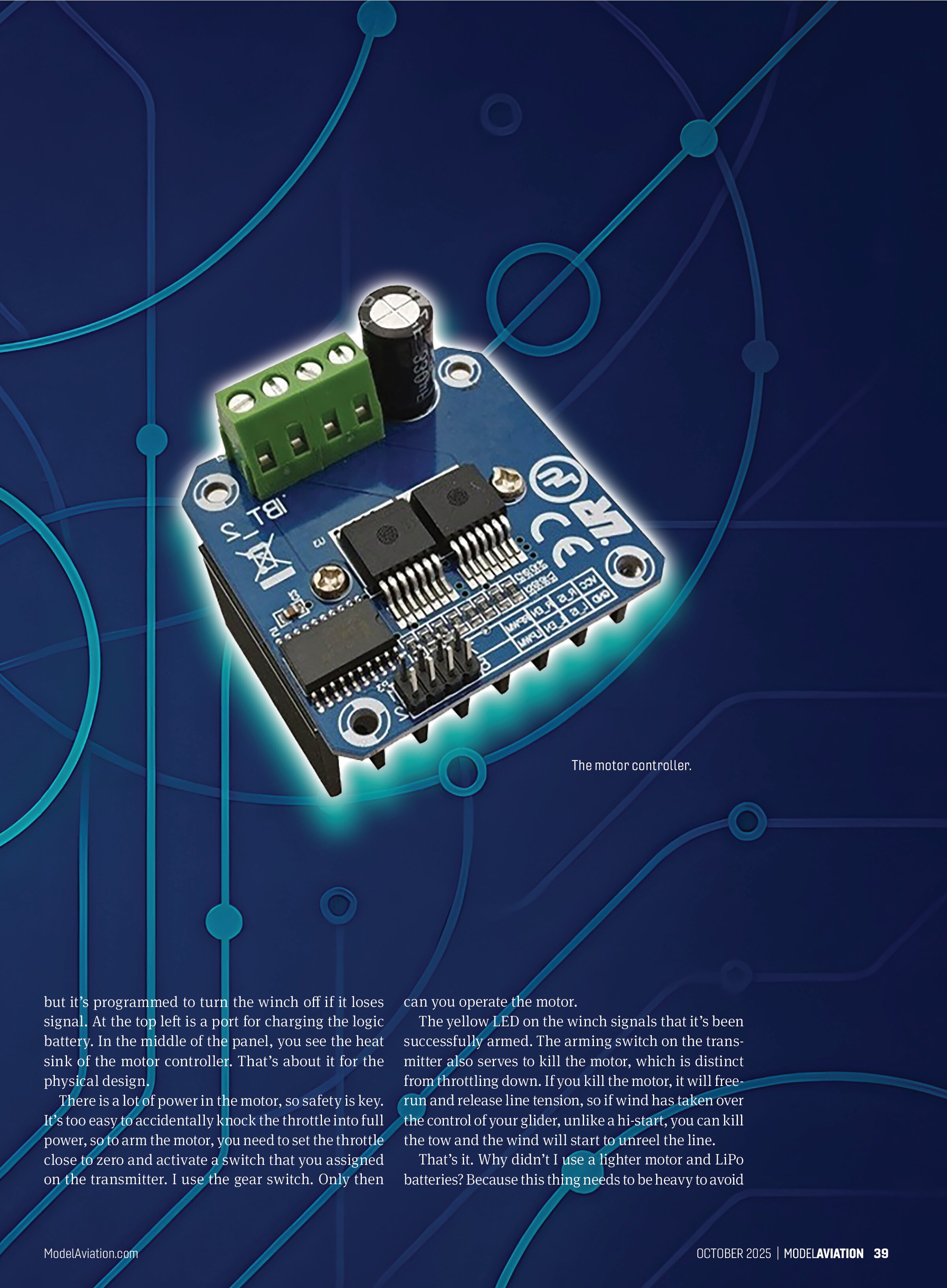
- BTS7960 43-amp high-power motor driver module
- 350- or 500-watt 24-volt DC brushed electric motor
- RUNCIL eight-strand braided fishing line
An exhaustive list would include wires, LEDs, knobs, switches, sockets, etc. I used 10K linear potentiometers for the dials, but anything similar would be fine. I have the CAD files in TurboCad format, but they can be exported to other formats.
It helps immensely to have access to a CNC machine to cut out accurate openings in the plastic box and to engrave the two-layer colored plastic for the face plates. Everything else will then fit perfectly. Similar to building a model aircraft, you’ll need—or have to gain—skills, such as working with electronics, a CNC machine, and CAD tools.
I’ve been using the glider winch that is outlined here for a couple of years now. It was a labor of love with trial and error to get it right, but the result is great. In brief, it uses two lead-acid batteries in series to power a large DC motor, which is controlled by the throttle lever on the transmitter. Hopefully you will find this article interesting and that, in case you want to do something similar, it provides some tips for getting it right.
Before reading further, let’s recap the pros and cons of the Radio Winch versus a hi-start winch:
- The hi-start winch is simple, reliable, cheap, and works.
- The Radio Winch offers setting the maximum power to suit the wind and the model, control of the power all the way up the climb, cutting the power if the launch needs to be aborted, and self-winding in of the line at the end of the day.
Yes, you can bind two receivers to the same transmitter. Both the winch and the glider are bound to the transmitter at the same time. The glider utilizes the control surface signals, and the winch utilizes the throttle switch, plus a toggle switch is used to arm it. You need to bind the winch to the transmitter, which is set to the particular glider that you plan to launch.
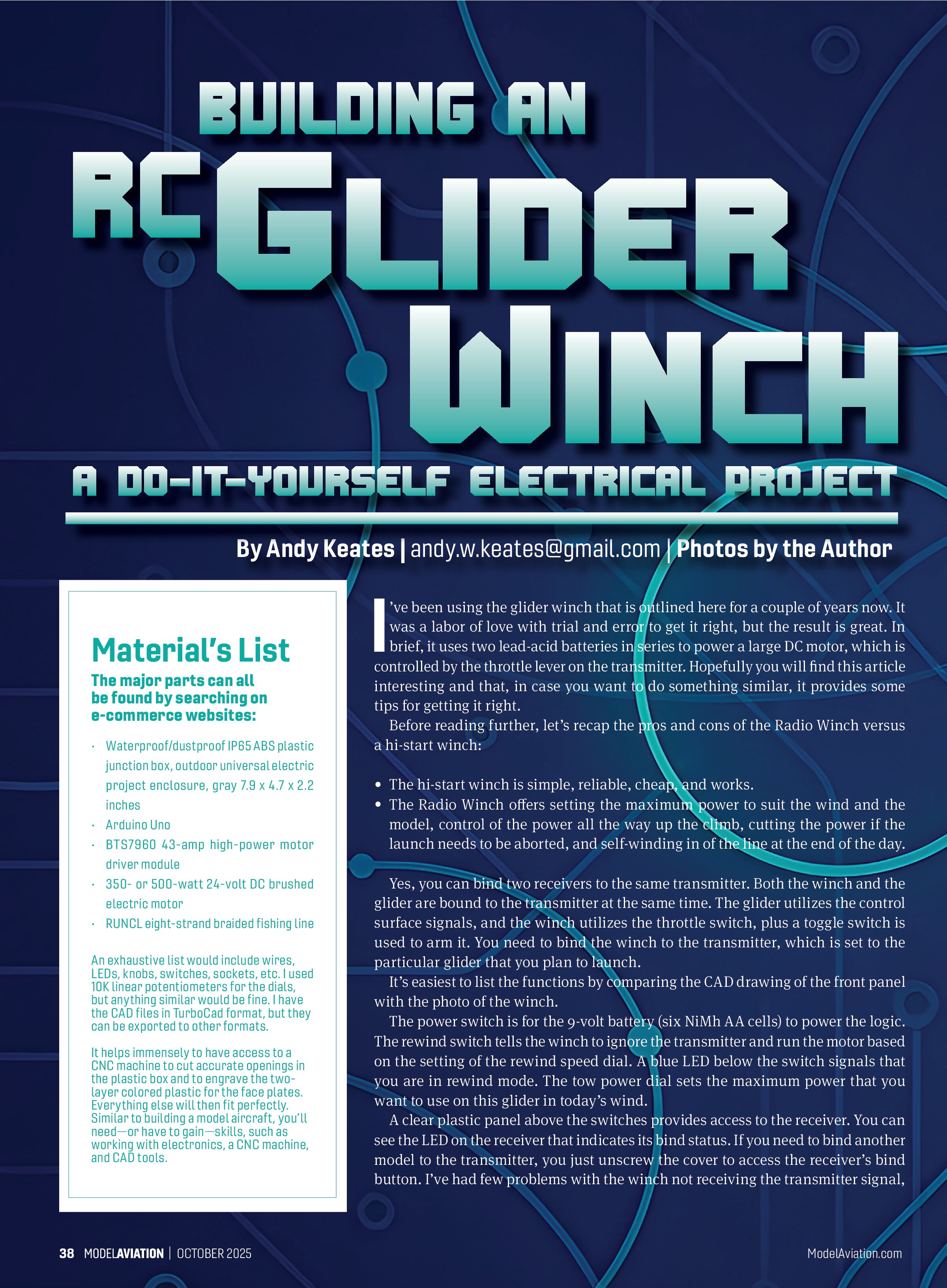
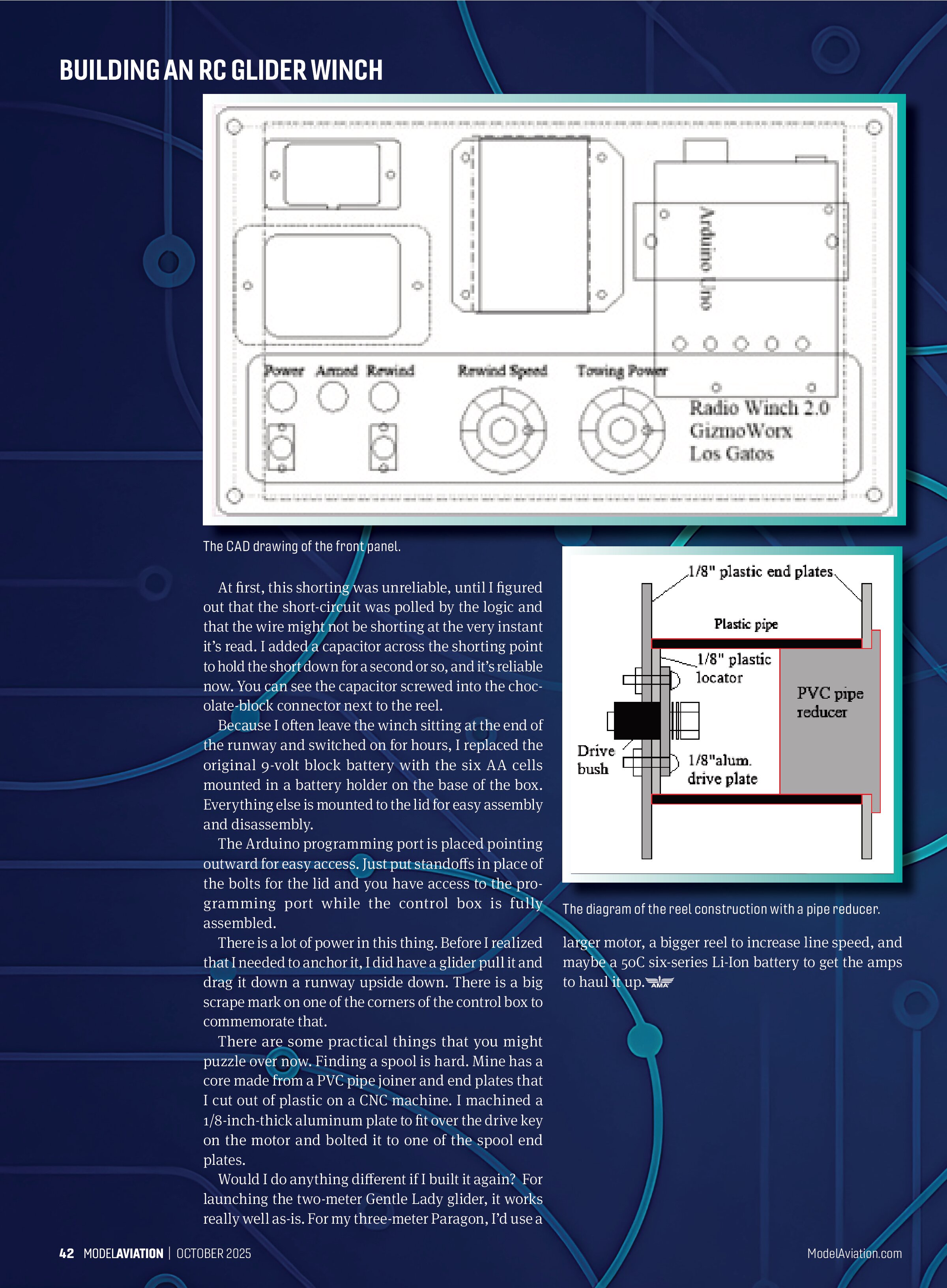
It’s easiest to list the functions by comparing the CAD drawing of the front panel with the photo of the winch.
The power switch is for the 9-volt battery (six NiMh AA cells) to power the logic. The rewind switch tells the winch to ignore the transmitter and run the motor based on the setting of the rewind speed dial. A blue LED below the switch signals that you are in rewind mode. The tow power dial sets the maximum power that you want to use on this glider in today’s wind.
A clear plastic panel above the switches provides access to the receiver. You can see the LED on the receiver that indicates its bind status. If you need to bind another model to the transmitter, you just unscrew the cover to access the receiver’s bind button. I’ve had few problems with the winch not receiving the transmitter signal,

but it’s programmed to turn the winch off if it loses signal. At the top left is a port for charging the logic battery. In the middle of the panel, you see the heat sink of the motor controller. That’s about it for the physical design.
There is a lot of power in the motor, so safety is key. It’s too easy to accidentally knock the throttle into full power, so to arm the motor, you need to set the throttle close to zero and activate a switch that you assigned on the transmitter. I use the gear switch. Only then can you operate the motor.
The yellow LED on the winch signals that it’s been successfully armed. The arming switch on the transmitter also serves to kill the motor, which is distinct from throttling down. If you kill the motor, it will free-run and release line tension, so if wind has taken over the control of your glider, unlike a hi-start, you can kill the tow and the wind will start to unreel the line.
That’s it. Why didn’t I use a lighter motor and LiPo batteries? Because this thing needs to be heavy to avoid
getting lifted off of the ground! It still needs to be anchored down. If the ground is soft, an auger for tethering a pet is good, but I now use a screw-in tent peg for the hard ground at the Santa Clara Model Aircraft Skypark in Morgan Hill, California.
Circuit Design
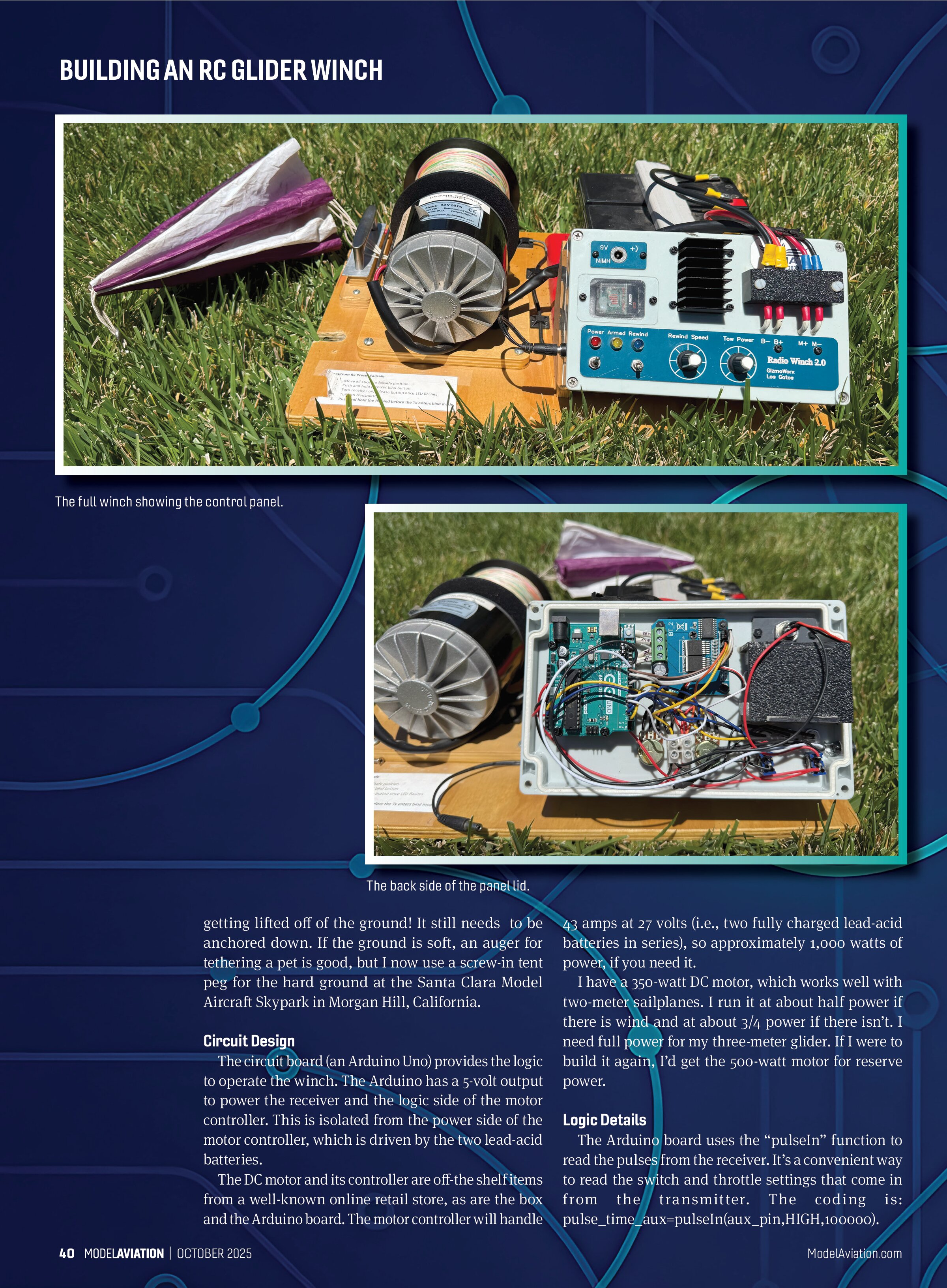
The circuit board (an Arduino Uno) provides the logic to operate the winch. The Arduino has a 5-volt output to power the receiver and the logic side of the motor controller. This is isolated from the power side of the motor controller, which is driven by the two lead-acid batteries.
The DC motor and its controller are off-the shelf items from a well-known online retail store, as are the box and the Arduino board. The motor controller will handle
43 amps at 27 volts (i.e., two fully charged lead-acid batteries in series), so approximately 1,000 watts of power, if you need it.
I have a 350-watt DC motor, which works well with two-meter sailplanes. I run it at about half power if there is wind and at about 3/4 power if there isn’t. I need full power for my three-meter glider. If I were to build it again, I’d get the 500-watt motor for reserve power.
Logic Details
The Arduino board uses the “pulseIn” function to read the pulses from the receiver. It’s a convenient way to read the switch and throttle settings that come in from the transmitter. The coding is: pulse_time_aux=pulseIn(aux_pin,HIGH,100000).

This command reads the servo pulse on the Arduino pin, christened “aux_pin,” to return how long the servo pulse was and gives up after 100,000μs if no pulse arrives. The result is stored in the pre-defined variable “pulse_time,” which gives the pulse width in μs. Once you have a number for the pulse width (i.e., the position of a lever or switch on the transmitter), you can do what you want with that information, such as implementing the logic to arm the winch. The Arduino has analog input pins to read the position of the two dials.
Trial-and-Error Learnings
Of course, things go wrong as you go through a learning curve, so here are the major things that I learned. First, the best towline is a multi-colored, braided, 100-pound strand fishing line. It’s easier to find in the


grass than monofilament line and will not default to a curled-up mess like twisted-filament lines.
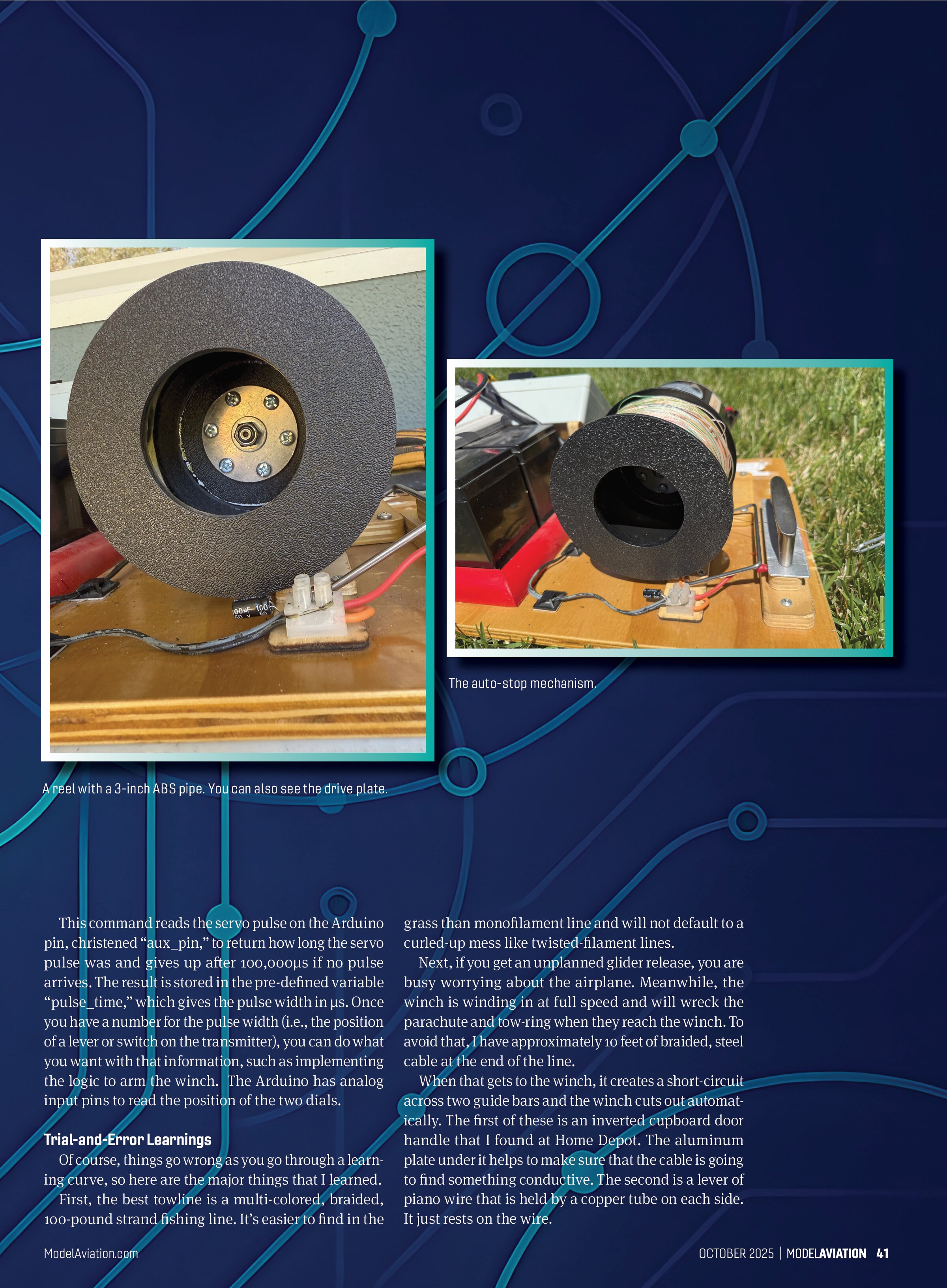
Next, if you get an unplanned glider release, you are busy worrying about the airplane. Meanwhile, the winch is winding in at full speed and will wreck the parachute and tow-ring when they reach the winch. To avoid that, I have approximately 10 feet of braided, steel cable at the end of the line.
When that gets to the winch, it creates a short-circuit across two guide bars and the winch cuts out automatically. The first of these is an inverted cupboard door handle that I found at Home Depot. The aluminum plate under it helps to make sure that the cable is going to find something conductive. The second is a lever of piano wire that is held by a copper tube on each side. It just rests on the wire.


At first, this shorting was unreliable, until I figured out that the short-circuit was polled by the logic and that the wire might not be shorting at the very instant it’s read. I added a capacitor across the shorting point to hold the short down for a second or so, and it’s reliable now. You can see the capacitor screwed into the chocolate-block connector next to the reel.
Because I often leave the winch sitting at the end of the runway and switched on for hours, I replaced the original 9-volt block battery with the six AA cells mounted in a battery holder on the base of the box. Everything else is mounted to the lid for easy assembly and disassembly.
The Arduino programming port is placed pointing outward for easy access. Just put standoffs in place of the bolts for the lid and you have access to the programming port while the control box is fully assembled.
There is a lot of power in this thing. Before I realized that I needed to anchor it, I did have a glider pull it and drag it down a runway upside down. There is a big scrape mark on one of the corners of the control box to commemorate that.
There are some practical things that you might puzzle over now. Finding a spool is hard. Mine has a core made from a PVC pipe joiner and end plates that I cut out of plastic on a CNC machine. I machined a 1/8-inch-thick aluminum plate to fit over the drive key on the motor and bolted it to one of the spool end plates.

Would I do anything different if I built it again? For launching the two-meter Gentle Lady glider, it works really well as-is. For my three-meter Paragon, I’d use a larger motor, a bigger reel to increase line speed, and maybe a 50C six-series Li-Ion battery to get the amps to haul it up.