
Sky Skanner
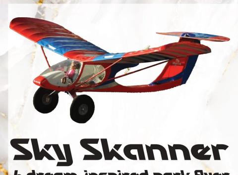
A dream-inspired park flyer
By Clark Salisbury
clarksalisbury@hotmail.com
Photos by the author
DISCOVER MORE CONTENT!
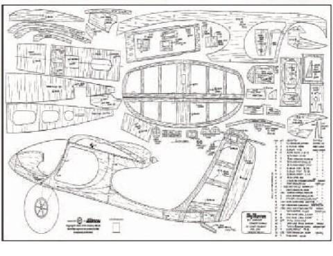
Download free plans at www.ModelAviation.com/plans.
Sometimes, you wake up in the middle of the night, having just had an interesting dream, and that dream is an inspiration for your next project. That happened to me! My dream had to do with a new airplane design, which would be a very lightweight aircraft. It would be able to carry two people in tandem, and would be battery powered for low noise level but be strictly for fun—no more than one-hour flight time and not designed for fast cross-country travel—just fly low and slow for the joy of flying.
In my dream, I envisioned it as having a cloth-covered wing and tail surfaces that would slip over a frame. Anyway, throughout the last 30 years now, I have designed quite a few RC airplanes, and when I woke up from this dream, I immediately thought about parts of other previous designs that would be incorporated into this new design to achieve my goal.
I hit my drawing board and what resulted was an airplane with a high-drag wing to keep speed down. This wing was originally on my Sky Crawler design of 2000. The fuselage is mostly from my recent Sky Viewer design from 2022, but this fuselage has the tailboom placed low, as on that of my Sky Skimmer design from roughly 10 years ago.
Having the tailboom low keeps the propeller from hitting the ground on takeoff. This new airplane has large, five-inch diameter wheels, so it can take off from grass, even if that grass has not been mowed for a while. It is a tail-dragger design to keep the weight down. So here you have it, the Sky Skanner, which is pronounced the same as sky scanner. Let’s have some fun building!
the horizontal stabilizer would be after the pieces have dried. This will be for the hinge placements. Test-fit the hinges, but do not glue them in at this point.
Fuselage Construction
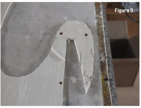
Figure 9 shows the top of the fuselage, with the plywood doubler glued to the left fuselage side. Be sure to create a right side also. Gluing the doubler in position obviously must be done on the other side of the right fuselage side panel. This step also connects the two pieces of the fuselage sides. Not shown, but still important, is gluing former F5 in place at the rear of the fuselage sides.
In Figure 10, formers F1 and F2 are in position. You will note that there are two F1 formers. On one of those F1s, you will need to cut off the top mounting tab because there is no place to locate it in the window pillars. Also shown is the plywood motor mount glued in position. I used glue sticks and bottled glue to keep these formers perpendicular to the fuselage sides.
The floorboard, which includes the landing gear mount, is spliced together on the side. There is a straight line on my building board to keep this floorboard perfectly straight.
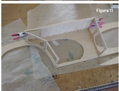
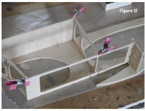
Figure 11 shows the floorboard glued in position and attached to the fuselage side and to the formers. Figure 12 is of the plywood fuselage. The cabin top piece is glued to the top of the formers and to the fuselage side.
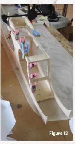
In Figure 13, the right fuselage side is glued to the assembly that you just built. Keep everything right on the centerline that is drawn on the building board. It wouldn’t hurt at this point to make sure that the rear of the fuselage comes together perfectly at the rear, where the F7 formers are located.
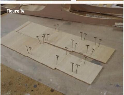
Figure 14 shows what will become the rear fuselage top and bottom pieces. These must be spliced and glued together so that the balsa grain direction allows you to achieve the bending that will be needed later.
[Editor’s note: Other pictures mentioned in this article are available online at www.ModelAviation.com or in the digital edition.]
In Figure 15, rear formers F3 and F4 are glued between the fuselage sides. Again, keep everything exactly centered by using the straight line on the building board. Also note that I am using the balsa rear fuselage jig to keep everything in line. This will ensure a good, straight vertical stabilizer later.
Figure 16 shows the rear fuselage top piece glued in position. Note that the rudder servo mount is on the left side. I did this so that I wouldn’t have to use servo reversing when I bind this aircraft to a radio transmitter that I already have.
In Figure 17, the front nose piece is glued in position to the fuselage side panels, and the front floorboard
has been glued in. It might be necessary to wet the floorboard slightly in order to curve it into shape on the bottom.
Figure 18 shows the battery box side pieces glued in place. They should be centered and be 1-3/4 inch apart to accommodate up to a 2,100 mAh battery, but I suggest a 1,300 mAh battery in the Bill of Materials printed on the plans.
The instrument panel sides, the instrument panel itself, and the instrument panel top are all glued in position in Figure 19. The assembly is held to the building board with pins to keep the width at 1-3/4 inch. Again, wet the top balsa piece for easier curving.
Figure 20 is of the fuselage rear bottom that is glued and pinned in place. I cut it in half 8-1/4 inches from its front. I will not glue the rear part in place until the servo wires and light wires have been fished through the fuselage bottom. It is shown lying on top.
Figure 21 shows the strut mounts glued in place on both sides of the fuselage bottom. They are glued at a 30° upward slant. If you use the 1/8-inch (stacked two-high) plywood gussets that you built, which were cut on a 30° angle, they will hold the strut mounts in the perfect position. Note that when the landing gear is screwed on, it will be exactly in line with these strut mounts.
In Figure 22, the E-flite 480 outrunner motor is bolted on the motor mount. If you do this now, it will be much easier than later when the top piece of balsa has been glued over the motor. I used a drop of Loctite on each of the four screws that hold the motor to the metal motor mount. I have heard that fingernail polish also works to keep those little screws tight.
Figure 23 shows the top of the balsa motor mount glued in position. Note the direction of the grain in the photo; that is important for bending. You will need to use four-inch C-clamps to hold it while it dries. The balsa will need to be wetted first to attain the desired curvature.
You can skip Figure 24 and the next few steps if you are not putting in lights, but I recommend that you do put them in. If nothing else, you can impress your friends with the static display hanging from your ceiling with lights on. Let’s face it—you probably won’t get a chance to fly this for everyone. It does require some fine soldering skills. Keep in mind that a short lead on an LED is always positive. If you wire it backward, the lights will not work.
Figure 24 shows the construction of the AAA battery holder. Shown in the photo, I spaced the sides up just the thickness of some small T-pins. Test the plastic battery holder to make sure that it fits before gluing.
Figure 25 shows the AAA battery holder glued into the bottom of the fuselage. I have bent a little wire clip to make sure that the batteries don’t fall out during flight, a bouncy landing, or during takeoff. The wire clip is not shown in the photo, but it is on the plans, slightly above the Bill of Material. There is no switch in
this system, so when you put the batteries in, the lights are on.
Bring all of your positive wires together to the red lead on the battery holder and all of the negatives to the black wire on the battery holder. Soldering these wires together is the best method, and you might want to add heat-shrink covering over the solder joints in case any of the joints touch each other.
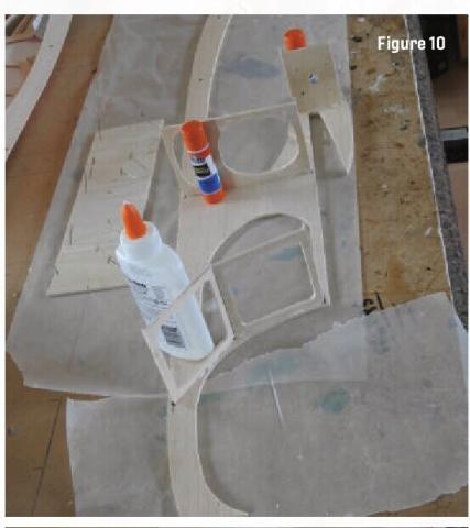
Figure 26 is of the wiring of the three LED lights that are on the right and the left wings. I used two white and one blue LED on each side of the wing. Figure 27 shows the horizontal stabilizer glued to the top of the vertical stabilizer. Before doing this, attach the 5/16-inch triangular gussets to both sides of the vertical stabilizer. You will have to notch out the gusset to make room for the elevator’s servo.
Notice that the vertical stabilizer has been grooved out for the wires that are coming down from the servo. Additionally, cut a rectangular groove into the top of the rear fuselage so that those wires can come through. For the elevator servo, you will be using the servo extension wires that you purchased. All of these wires are going to go forward to your receiver, which will be placed behind former F2.
When gluing the horizontal stabilizer to the vertical stabilizer, make sure that you keep everything perpendicular. In this same step, although not shown, mount the rudder servo to the top of the rear fuselage. When this is done, glue this entire assembly to the top of the rear fuselage through the cut slots and through the slot in the bottom of the fuselage. Test-fit the assembly before gluing and maintain perpendicularity when you glue this together.
Figure 28 shows the pilot in the seat. I used a Chelsea doll from Walmart and had to heat her legs to get them to bend down. I also modified the front of the seat by adding a couple of 3/8-inch diameter dowels that were cut 1/4 inch high to the front of the seat. I used a toothpick to simulate two joysticks coming out of those dowels. A zip tie keeps my pilot from falling out of her seat.
The wing struts are also attached in this photo. The wing struts serve two purposes. One is to keep the wing from breaking in a loop or in turbulence. The wing by itself is not structurally strong enough otherwise. The other purpose is to be able to adjust the washout of the wing on each side. The clevis ends allow some adjustment.
Make sure that you keep roughly 1/4 inch of washout on both wing halves at the tips. In other words, the rear of the wing should be up roughly a quarter inch compared with the front of the wing at the tips. Washout makes the airplane much easier to fly.
Final Assembly
I did not call out a brand of receiver or radio in the Bill of Materials because, nowadays, you can bind many models to the same transmitter. After you have bound the radio, carefully check the propeller rotation to make sure that it pushes the airplane forward, and not backward. If it does want to push the model backward, changing any two of the wires that go to the ESC from the motor will correct the problem.
Make sure that your servos cause the control surfaces to go in the correct direction. My preference is to have 15° of control surface movement at full deflection of your joysticks for both rudder and elevator.
Flying the Sky Skanner
They say a picture is worth a thousand words, so if you look up the video of the Sky Skanner’s maiden flight, which is on my YouTube channel (listed in “Sources”), you can see it for yourself, and that’s worth more like a million words!
This airplane is easy to fly, although it only has three-channel control. The wire tail skid simply drags through the grass and keeps the airplane going straight with no rudder input during takeoff. I imagine taking off from a paved surface would require some rudder input, but I haven’t tried that yet.
Apply full throttle on takeoff to overcome the resistance from tall grass. After the airplane becomes airborne, you can throttle back to half or even one-third throttle stick. My favorite flights are slow, low, and close. I like to be able to clearly see the airplane and what it is doing. This is where the Sky Skanner excels. Because of the high-drag wing, you will have to keep a little throttle as you land. It can make dead-stick landings, but you’ll be surprised at how quickly it will lose altitude with no power at all.
This is a relaxing airplane to fly. I made the maiden flight myself, with my wife shooting video. I usually ask a more experienced pilot to make a maiden flight, but not with this airplane. Enjoy flying it! I sure do!
SOURCES:
AMA Plans Service
(765) 287-1256, ext. 507
https://plans.modelaircraft.org
APC Propeller
(530) 661-0399
www.apcprop.com
E-flite
www.horizonhobby.com/e-flite-1
Loctite
(800) 624-7767
www.loctiteproducts.com
Clark Salisbury’s YouTube channel
www.youtube.com/@clarksalisbury2361


