
RC SCALE AEROBATICS

PROPER
TECHNIQUES
FOR
CONSISTENT
PERFORMANCE
By John Glezellis | jglezellis@gmail.com
AS YOU BECOME more involved within the competition scene, you will soon realize that success is partly because of your ability as the pilot. You will also see the importance of other factors that include, but are not limited to, the understanding and proper application of the rule book, overall design of the aircraft, and how the model is mechanically built and programmed.
Throughout the course of this column, I will examine a few proper techniques that you should implement to obtain consistent performance. Many items are essential to ponder during the initial setup and programming stages and will benefit the pilot once they are at the field so that they can focus on perfecting the next International Miniature Aerobatic Club (IMAC) maneuver.
Because examples are always helpful, I will not only discuss a few flight and judging criteria elements but also show how certain setup oversights can impact the flight behavior in a figure such as the Hammerhead.
Without further delay, let’s get started!
Building and Programming Basics
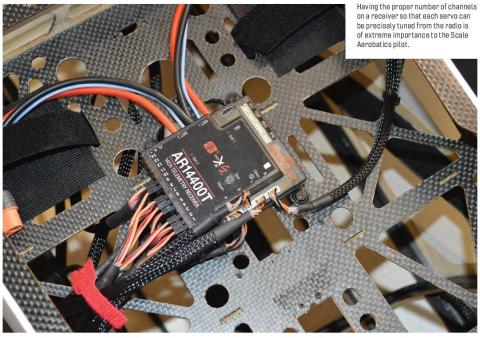
During the equipment selection process, it is important that the receiver has the necessary amount of servo and/or accessory ports to prevent future heartache. A 35cc aircraft can easily utilize a seven-channel receiver with two elevator servos, two aileron servos, a single servo for the throttle and rudder, and lastly, a port used for an optical kill switch or an ignition battery eliminator circuit, if desired. I have often seen people who are getting into Giant Scale Aerobatics utilize six-channel receivers with the use of Y harnesses to reduce the receiver channel count that is needed.
As I touched upon in a 2024 column, a Y harness will not allow you to adjust the upward travel of both ailerons compared with the downward travel, to adjust each elevator servo, or to make necessary adjustments to multiple servos for a given control surface in an independent manner, since all changes will apply to all servos that are connected to the Y harness.
During the linkage installation process, it is good practice to measure and document the length of the total available threads on one end of the linkage. Personally, I measure the available threads on the Hangar 9 Titanium Pro-Links linkage and will begin threading a ball link or clevis, if applicable, so that it uses half of the available threads. Should the assembly need to be lengthened, you can loosen the ball link a few turns to ensure that sufficient threads are available by referencing the measurement noted earlier. Using subtrim to fine-tune the center position of the servo so that it is perfectly parallel to the hinge line is oftentimes required.
Lastly, the use of threadlocker on the servo arm output shaft of a metal-gear servo when you are using aluminum servo arms is imperative. Some threadlocking adhesives can harm plastic, while others are designed for plastic and feature a relatively low strength that is intended for use with, for example, a plastic servo arm. Should my model feature a plastic servo arm, I use a dab of Zap Goo adhesive on the servo arm screw and the inner wall of the servo arm to make certain that the screw stays in position.
Let’s see how a few of the items noted above can impact a figure.
Maneuver Overview
While the throttle settings that are required might differ because of the general power-to-weight ratio, for the Hammerhead maneuver found in the 2025 IMAC Intermediate program, a throttle

Always document the total length of available threads to guarantee the proper positioning of the ball link or clevis, if applicable, and to minimize the chance of a linkage failing because of it being only captured on a thread or two. The author uses Hangar 9 Pro-Links and Du-Bro ball links because he has experienced issues with other brands where a linkage slipped by a thread or two—and it happened in flight!
RC SCALE AEROBATICS

setting between 75% and 90% is generally preferred as a starting point. Once the aircraft is in the proper inverted position within the aerobatic airspace, you will need to push to perform a gradual ¼ outside loop to establish a vertical line. Equal travel of the elevator halves is needed to prevent any rolling tendency of the model during the radius that will result in a deduction. During the push, the wing must be perfectly level—corrective inputs will otherwise be required.
After the model is tracking perfectly vertical and a desired line segment is shown, perform a ¼ roll where you will either see the top or bottom of the model depending on the direction of the roll. Some might prefer to roll in a direction where, once it’s complete, the top of the aircraft will face you, which will ease any corrective inputs that are required in terms of direction. Perform an equal line segment, where you will decrease power. Should the aileron differential not be set up properly, the roll might not be axial, which will result in a downgrade. For these reasons, it is critical to have the ability to adjust differential and independently adjust the servo settings.
If wind exists, the airplane must be angled into it for vertical segments so that the flight path will be perfectly vertical; otherwise, one point per 10° will be deducted. While pulling back on the throttle as the airplane nears a complete stop, add rudder to pivot the aircraft 180°, preferably into the wind. Once it’s stopped, the model must pivot in a plane that is parallel to the vertical line. Any deviation will be downgraded by a half point for each 5°.
During the pivot, no pendulum movement in yaw should exist. Pendulum movement might show because of a quick rudder release or a loose rudder pull-pull cable configuration, which can be half a point per 5° of movement. If you are using pull-pull cables, always confirm that the cables are slightly taught.
Periods in which the aircraft is at a stalled state do not need to be wind corrected. Any wind drift shall be disregarded by the judges and not downgraded. Allow the model to track on the downline and execute a half roll followed by an opposite ¼ roll to exit inverted. Again, the rolling elements must be positioned so that the line segments before and after the roll elements are of equal length.
My personal models are configured in a manner where I will perform all pitch and rolling elements for the Hammerhead on my first flight mode, which features a large rudder deflection amount coupled with relatively low elevator and aileron deflections. Generally, I have found the deflection amounts noted in the table below as a great starting point for most 35cc to 200cc aerobatic models.
If you feel that your airplane is either too sensitive or relaxed in feel, make the necessary adjustments to either the control throws and/or exponential settings. However, never change exponential values in large increments; instead, add exponential in 5% increments and take note of how it gradually changes the flight characteristics of the model.
Depending on the aircraft, times have existed where the exponential that is used for up-elevator differs in value compared with what I’ve used for down-elevator. The goal is for the aircraft to have a similar feel when performing a positive verses negative pitch change.
Finally, always check with the instruction manual of your radio manufacturer to ensure that exponential is being added in the right direction. What is noted in the table is for a Spektrum system (positive exponential value).

Final Thoughts
Proper build, setup, and practice techniques are all contributing factors to success, in addition to the ability of the pilot. Trophies aside, please enjoy all that this fine sport has to offer, and take advantage of modern-day radio systems, engines, electronics, and aircraft designs.
Now, get out to the field and get practicing!
Until next time, fly hard!
SOURCES:
IMAC
www.mini-iac.org
Horizon Hobby
www.horizonhobby.com
Du-Bro
(800) 848-9411
www.dubro.com
Robart Manufacturing/Zap Adhesives
(630) 584-7616
https://robart.com/pages/zap-glue


