Build The Wanderer
This FF model is comfortable in smaller spaces

By Pat Tritle
patscustommodels@gmail.com
After building a number of Sport Free Flight (FF) designs throughout the years, I’m always on the lookout for something slightly out of the ordinary. When it comes to biplanes, cabin-types are a plus—they’re so easy to set up, primarily because there are no cabane struts to attach or align. Being a fan of Scale models, the thought of designing a Sport model that has a scalelike appearance also has a significant appeal.
The Wanderer not only has a scalelike appearance but also lends itself well to trying an uncommon setup. In that realm, it looked like a terrific way to delve into experimenting with forward-swept wings. At the same time, not wanting to swerve too far off the centerline, I thought that an aft-swept top wing and a forward-swept bottom wing might be great starting points into the unknown.
As it turns out, the concept not only worked, but it worked well, and the prototype virtually flew off the drawing board. The model is extremely stable in the air and was making 30-second flights by the third powered trim flight, with only one minor downthrust adjustment after the first powered flight with 200 turns on the motor.
After increasing the number of winds to 900 turns and one minor side-thrust adjustment, the model was doing consistent 50- to 55-second flights in still air. All things considered, the Wanderer is the easiest biplane to trim that I’ve ever had.


For those who have avoided building biplanes because they don’t want to have to fiddle with tricky wing alignment, the Wanderer would be a terrific way to break into FF biplanes.
The Model
The design is basic, with no curved outlines except for the aft upper and forward lower fuselage longerons. With no rounded outlines needed for the wings or tail, the parts count is held to a bare minimum. At the same time, the model builds up nice and light but still has pleasing lines without ending up with a boxy-looking airframe.
Framing the Wanderer
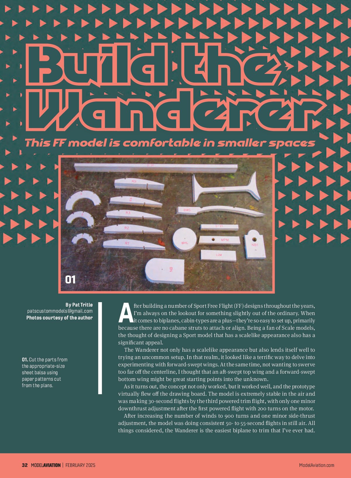
Construction begins by cutting all of the parts from the appropriate thickness of sheet balsa. I also bent the landing gear components and laminated the main gear between the two landing gear mount plates so that it would be handy when construction began.
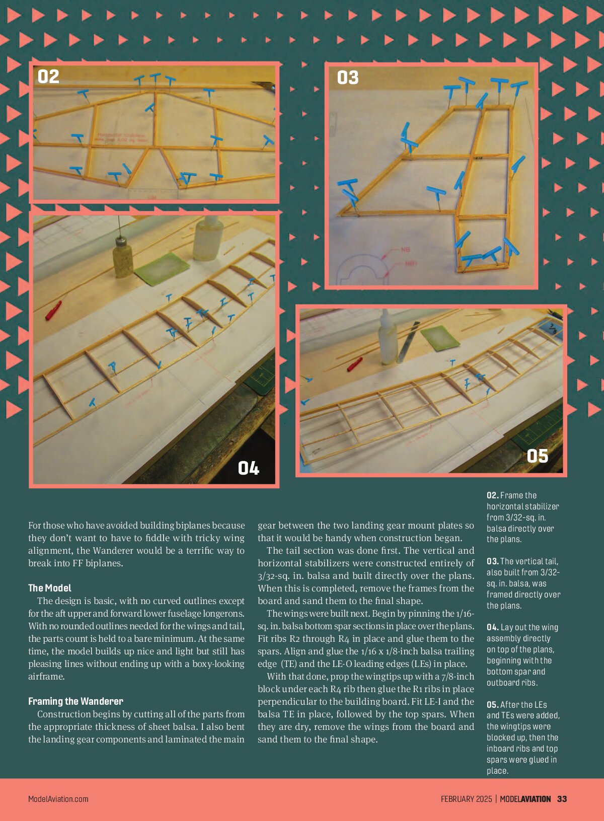
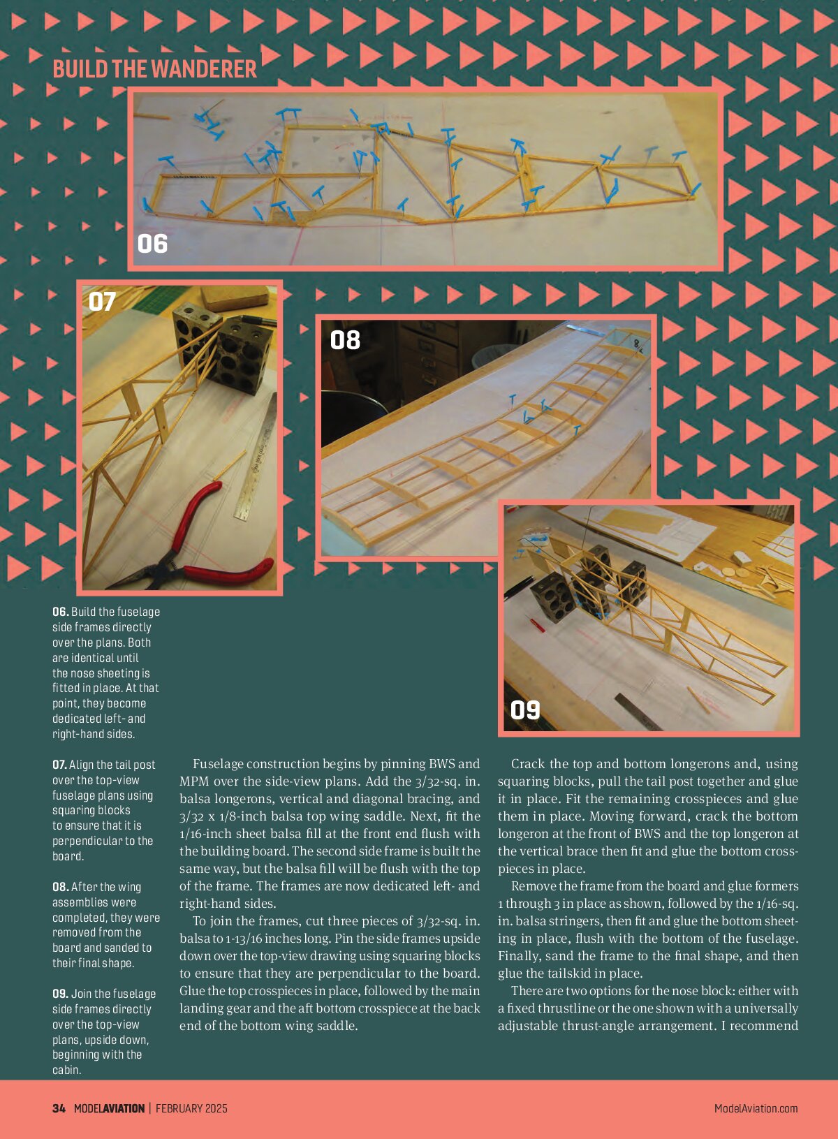
The tail section was done first. The vertical and horizontal stabilizers were constructed entirely of 3/32-sq. in. balsa and built directly over the plans. When this is completed, remove the frames from the board and sand them to the final shape.
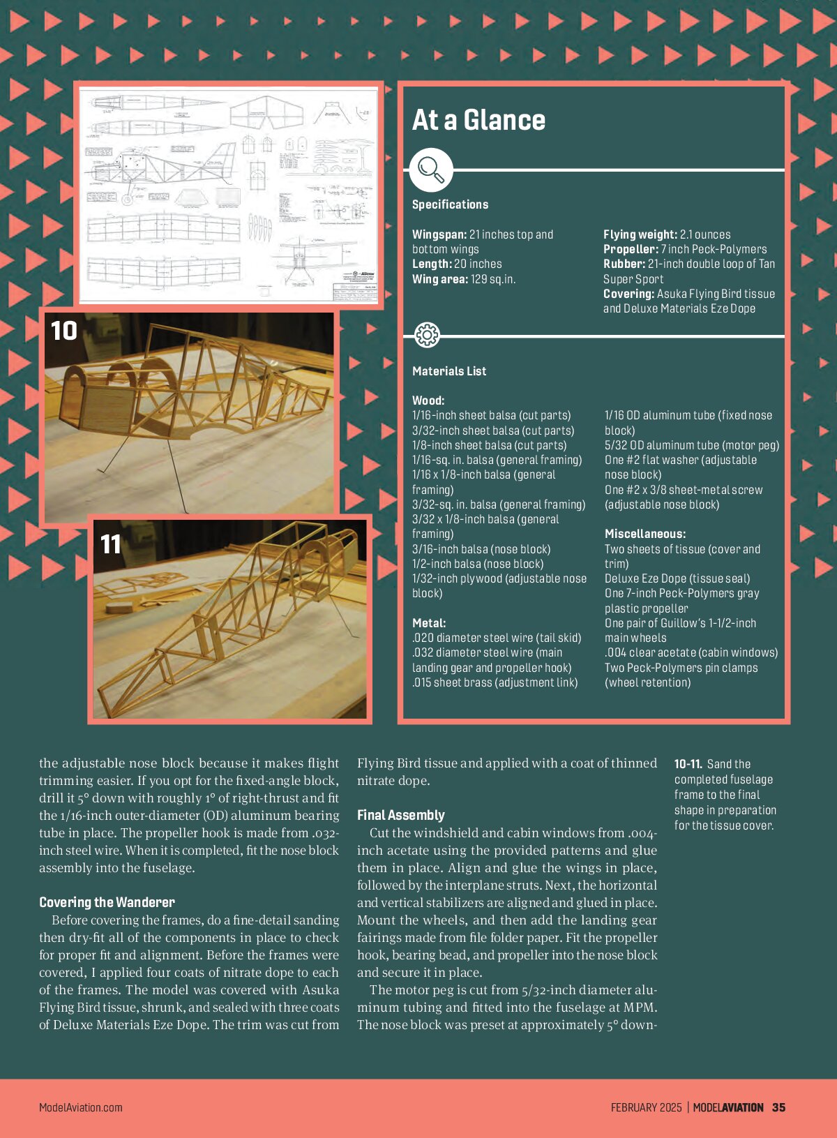
The wings were built next. Begin by pinning the 1/16-sq. in. balsa bottom spar sections in place over the plans. Fit ribs R2 through R4 in place and glue them to the spars. Align and glue the 1/16 x 1/8-inch balsa trailing edge (TE) and the LE-0 leading edges (LEs) in place.
With that done, prop the wingtips up with a 7/8-inch block under each R4, rib then glue the R1 ribs in place perpendicular to the building board. Fit LE-1 and the balsa TE in place, followed by the top spars. When they are dry, remove the wings from the board and sand them to the final shape.
BUILD THE WANDERER


Fuselage construction begins by pinning BWS and MPM over the side-view plans. Add the 3/32-sq. in. balsa longerons, vertical and diagonal bracing, and 3/32 x 1/8-inch balsa top wing saddle. Next, fit the 1/16-inch sheet balsa fill at the front end flush with the building board. The second side frame is built the same way, but the balsa fill will be flush with the top of the frame. The frames are now dedicated left- and right-hand sides.
To join the frames, cut three pieces of 3/32-sq. in. balsa to 1-13/16 inches long. Pin the side frames upside down over the top-view drawing using squaring blocks to ensure that they are perpendicular to the board.
Glue the top crosspieces in place, followed by the main landing gear and the aft bottom crosspiece at the back end of the bottom wing saddle.
Crack the top and bottom longerons and, using squaring blocks, pull the tail post together and glue it in place. Fit the remaining crosspieces and glue them in place. Moving forward, crack the bottom longeron at the front of BWS and the top longeron at the vertical brace then fit and glue the bottom crosspieces in place.
Remove the frame from the board and glue formers 1 through 3 in place as shown, followed by the 1/16-sq. in. balsa stringers, then fit and glue the bottom sheeting in place, flush with the bottom of the fuselage. Finally, sand the frame to the final shape, and then glue the tailskid in place.
There are two options for the nose block: either with a fixed thrustline or the one shown with a universally adjustable thrust-angle arrangement. I recommend
the adjustable nose block because it makes flight trimming easier. If you opt for the fixed-angle block, drill it 5° down with roughly 1° of right-thrust and fit the 1/16-inch outer-diameter (OD) aluminum bearing tube in place. The propeller hook is made from .032-inch steel wire. When it is completed, fit the nose block assembly into the fuselage.
At a Glance
Specifications
Wingspan: 21 inches top and bottom wings
Length: 20 inches
Wing area: 129 sq. in.
Flying weight: 2.1 ounces
Propeller: 7-inch Peck-Polymers
Rubber: 21-inch double loop of Tan Super Sport
Covering: Asuka Flying Bird tissue and Deluxe Materials Eze Dope
Materials List
Wood:
1/16-inch sheet balsa (cut parts)
3/32-inch sheet balsa (cut parts)
1/8-inch sheet balsa (cut parts)
1/16-sq. in. balsa (general framing)
1/16 x 1/8-inch balsa (general framing)
3/32-sq. in. balsa (general framing)
3/32 x 1/8-inch balsa (general framing)
3/16-inch balsa (nose block)
1/2-inch balsa (nose block)
1/32-inch plywood (adjustable nose block)
1/16 OD aluminum tube (fixed nose block)
5/32 OD aluminum tube (motor peg)
One #2 flat washer (adjustable nose block)
One #2 x 3/8 sheet-metal screw (adjustable nose block)
Metal:
.020 diameter steel wire (tail skid)
.032 diameter steel wire (main landing gear and propeller hook)
.015 sheet brass (adjustment link)
Miscellaneous:
Two sheets of tissue (cover and trim)
Deluxe Eze Dope (tissue seal)
One 7-inch Peck-Polymers gray plastic propeller
One pair of Guillow’s 1-1/2-inch main wheels
.004 clear acetate (cabin windows)
Two Peck-Polymers pin clamps (wheel retention)
Flying Bird tissue and applied with a coat of thinned nitrate dope.
Covering the Wanderer
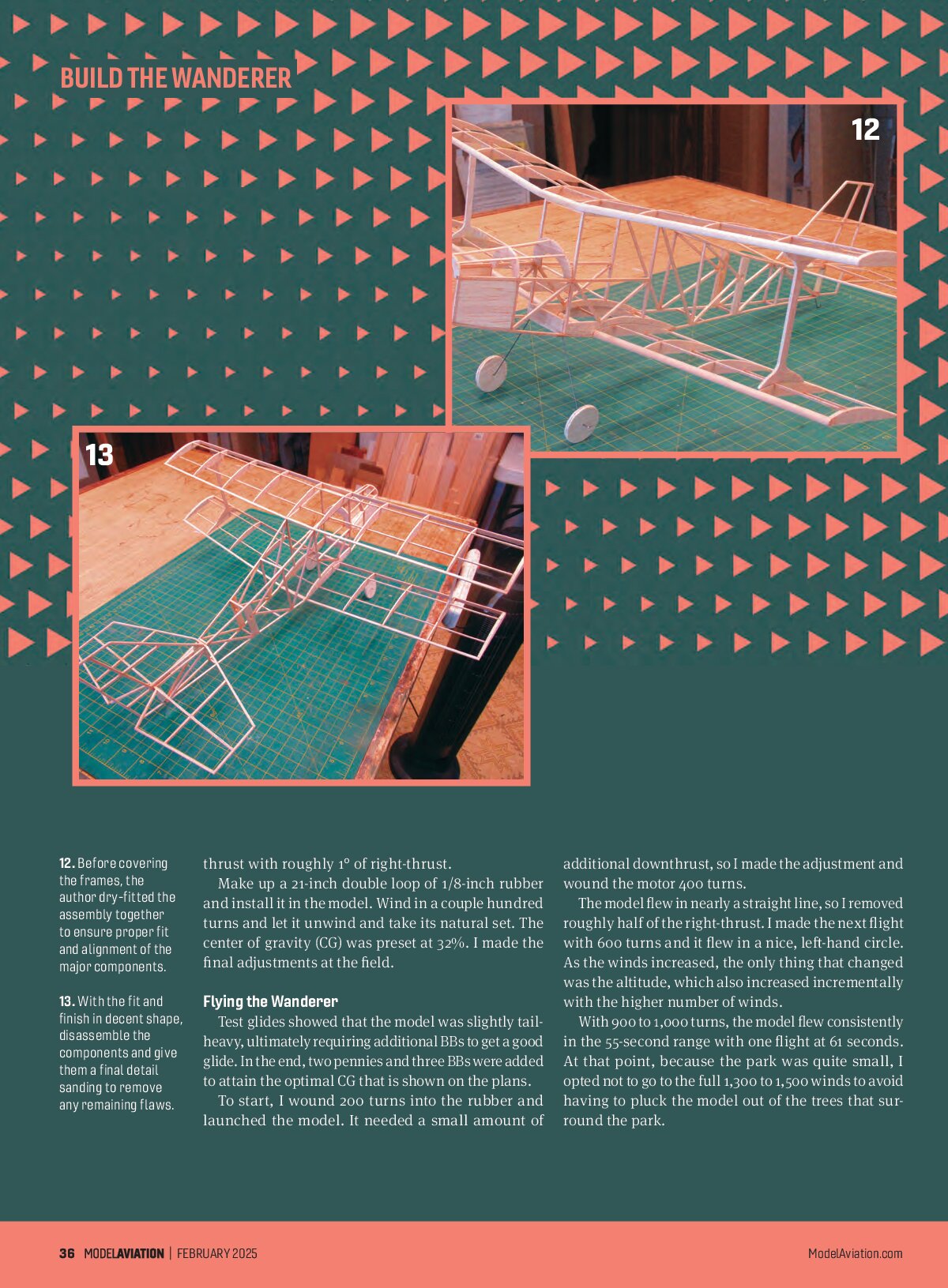
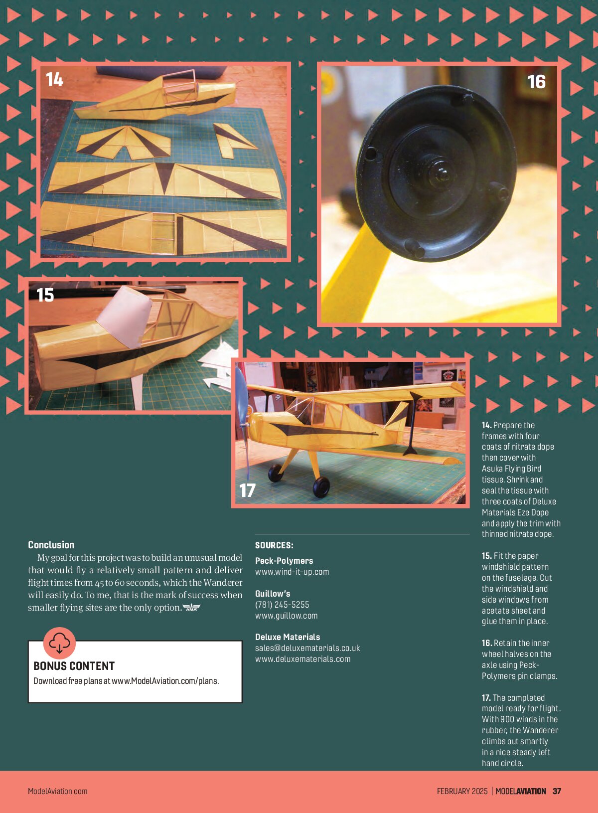
Before covering the frames, do a fine-detail sanding then dry-fit all of the components in place to check for proper fit and alignment. Before the frames were covered, I applied four coats of nitrate dope to each of the frames. The model was covered with Asuka Flying Bird tissue, shrunk, and sealed with three coats of Deluxe Materials Eze Dope. The trim was cut from

Final Assembly
Cut the windshield and cabin windows from .004-inch acetate using the provided patterns and glue them in place. Align and glue the wings in place, followed by the interplane struts. Next, the horizontal and vertical stabilizers are aligned and glued in place. Mount the wheels, and then add the landing gear fairings made from file folder paper. Fit the propeller hook, bearing bead, and propeller into the nose block and secure it in place.
The motor peg is cut from 5/32-inch diameter aluminum tubing and fitted into the fuselage at MPM. The nose block was preset at approximately 5° down-


Build The Wanderer


Make up a 21-inch double loop of 1/8-inch rubber and install it in the model. Wind in a couple hundred turns and let it unwind and take its natural set. The center of gravity (CG) was preset at 32%. I made the final adjustments at the field.
Flying the Wanderer
Test glides showed that the model was slightly tail-heavy, ultimately requiring additional BBs to get a good glide. In the end, two pennies and three BBs were added to attain the optimal CG that is shown on the plans.
To start, I wound 200 turns into the rubber and launched the model. It needed a small amount of additional downthrust, so I made the adjustment and wound the motor 400 turns.
The model flew in nearly a straight line, so I removed roughly half of the right-thrust. I made the next flight with 600 turns and it flew in a nice, left-hand circle. As the winds increased, the only thing that changed was the altitude, which also increased incrementally with the higher number of winds.
With 900 to 1,000 turns, the model flew consistently in the 55-second range with one flight at 61 seconds. At that point, because the park was quite small, I opted not to go to the full 1,300 to 1,500 winds to avoid having to pluck the model out of the trees that surround the park.


Conclusion
My goal for this project was to build an unusual model that would fly a relatively small pattern and deliver flight times from 45 to 60 seconds, which the Wanderer will easily do. To me, that is the mark of success when smaller flying sites are the only option.
SOURCES:
Peck-Polymers
www.wind-it-up.com
Guillow’s
(781) 245-5255
www.guillow.com
Deluxe Materials
sales@deluxematerials.co.uk
www.deluxematerials.com
BONUS CONTENT
Download free plans at www.ModelAviation.com/plans.