Build The F4U-1A Corsair Park Flyer
Add this reader-selected project to your hangar
By Derek Micko
derekmicko3@hotmail.com
Photos by the author

Few aircraft have a more distinctive shape than the Chance Vought F4U Corsair. It featured an iconic inverted gull-wing design, a massive three- or four-blade propeller, and a long nose. It was a welcome sight to Allied forces, and its characteristic whistle struck fear in its opponents.
Powered by the famous R2800 radial engine, it was the first single-engine US fighter aircraft to exceed 400 mph. The Corsair had the longest production run for any piston-powered aircraft, from 1940 to 1953, with more than 12,500 examples built by three companies.
It flew with the U.S. Navy, U.S. Marine Corps (USMC), Fleet Air Arm (FAA Britain), the French Navy, Royal Australian and Royal New Zealand air forces, and the Honduran Air Force. It served in both the Pacific and European theaters. The radical design presented some initial issues that needed to be overcome before being fully operational with the U.S. Navy.
The aircraft’s large, 13-foot diameter propeller and powerful engine produced a significant amount of torque. This, coupled with the tendency to stall sharply to the left, caused some early accidents and earned the Corsair the nickname of the “Ensign Eliminator.”
The long nose of the F4U also made conventional carrier landings (straight-in approach) difficult because the cowling would block the pilot’s view during the last critical phase. While Chance Vought worked through these teething challenges, the Corsairs initially flew with the USMC and the FAA Britain; their speed, fire power, and climb rate quickly proved them to be an effective fighter.
The British pilots developed and tested the “curved approach” for carrier landings—this significantly increased visibility and safety. Once proven with the FAA Britain, the U.S. Navy started adding them to its aircraft carriers. It was not long before the F4U showed its virtues


BUILD THE F4U-1A CORSAIR PARK FLYER

as both a fighter and a ground-attack aircraft, resulting in the “Bent Winged Bird” to obtain more positive nicknames: “The Sweetheart of the Marianas” and “The Angel of Okinawa.” The Corsair had an 11:1 kill ratio in World War II and had air-to-air victories in Korea and other conflicts.
When putting together the list of aircraft for the “Next Model Design” poll, I knew I had to have the Corsair as one of the options, and I was pleasantly surprised to hear that it had won out over the P-39 in a close race. While keeping with the “park flyer-size” theme, I also wanted to offer some unique options for builders. Working with Manzano Laser Works and Rabid Models, the model can be built with several exciting options.
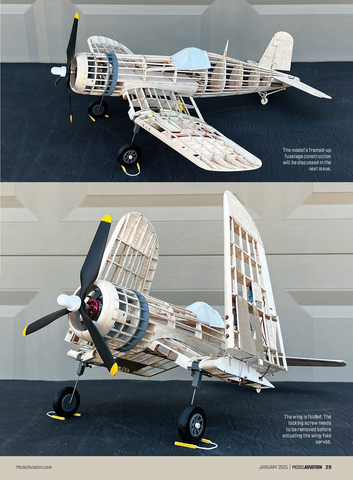
The wing can be built with plug-in landing gear or as a “belly flopper.” It can be built with not only mechanical 90° rotating retracts, but also a folding wing! Both the wing articulation and the retracts are controlled by micro servos utilizing in-line speed reducers. If the builder’s transmitter has a speed option, these can be eliminated. The retracts, wing-folding parts, wheels/hubs, control horns, strut covers, and propeller hub are 3D-printed options from Rabid Models, along with a power pack.

Manzano Laser Works offers the short kit in several options that are based on which version you want to build. In addition to the full-size plans and parts templates available on www.ModelAviation.com, there are printed tissue templates, cockpit/pilot details, and construction/covering notes available for download. An in-depth build thread with construction photos is on RCGroups, and multiple videos are on my YouTube channel, Fun Scale Models (see Sources).
The model is primarily built from 3/32-inch balsa and 1/8-inch light plywood. There are also some 1/16-inch and 1/4-inch balsa, and some 3/32-inch square basswood. The model will need four channels/servos

for the standard wing (SW) version: ailerons (two), rudder, and elevator. It will require eight channels and servos for the retract/folding wing (RFW) version: ailerons (two), rudder, elevator, retracts (two), and wing fold (two). All of the servos are 4.3 to 5 grams, except for the 9-gram wing-fold servo. The retract and wing-fold servos are metal geared.
The RFW is made up of nine panels and the SW is from seven. The SW build is quite similar to that of the RFW, and additional details for the SW and the model overall can be found in the construction/covering notes.
This installment will cover construction of the RFW. A second part in the next issue of Model Aviation will complete the construction.
RFW
Begin by cutting the leading edge (LE) blanks from medium 1/4-inch balsa and the trailing edge (TE) from

3/32-inch balsa using the templates on the plans. Glue the washout jigs (WOJ), aileron leading edge (ALE), wingtip guides (WTG), the wing panel 2 LE, S5/S5A, S7/S7A, S8/S8A, and S9/S9A subassemblies together. Be sure to make a right and a left version.
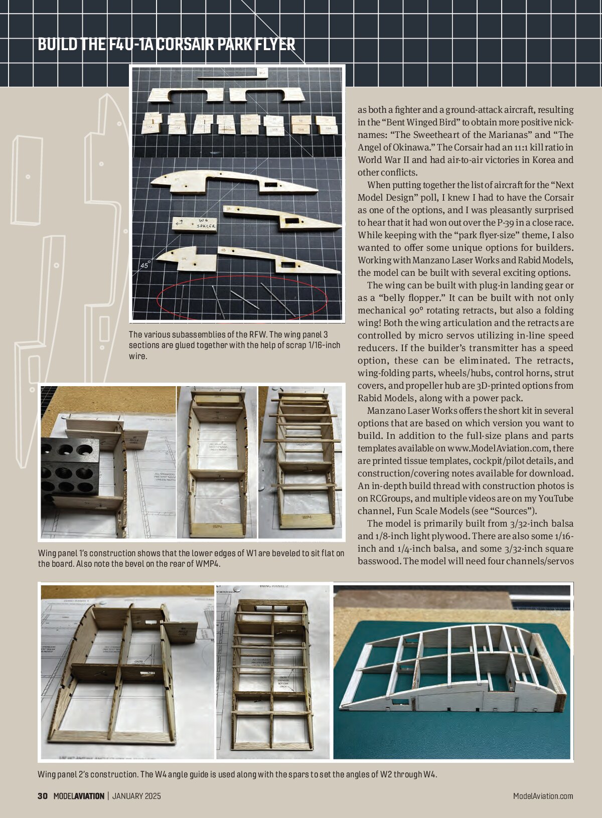
Place waxed paper or clear film over the wing plans to protect them during construction. Pin the LE, WMP4, S1, and S2 in place over the plans of wing panel 1. Sand/bevel the bottom edge of the W1S so that they sit flat on the board before gluing in place (use the W1 angle guide to assist with alignment).
Add the 3/32-inch balsa stringers, top and bottom, along with WMP2. Build the right wing panel 2 the same way, beveling the top and bottoms of W2 and W4 and using the angle guides and S3/S4 for alignment.
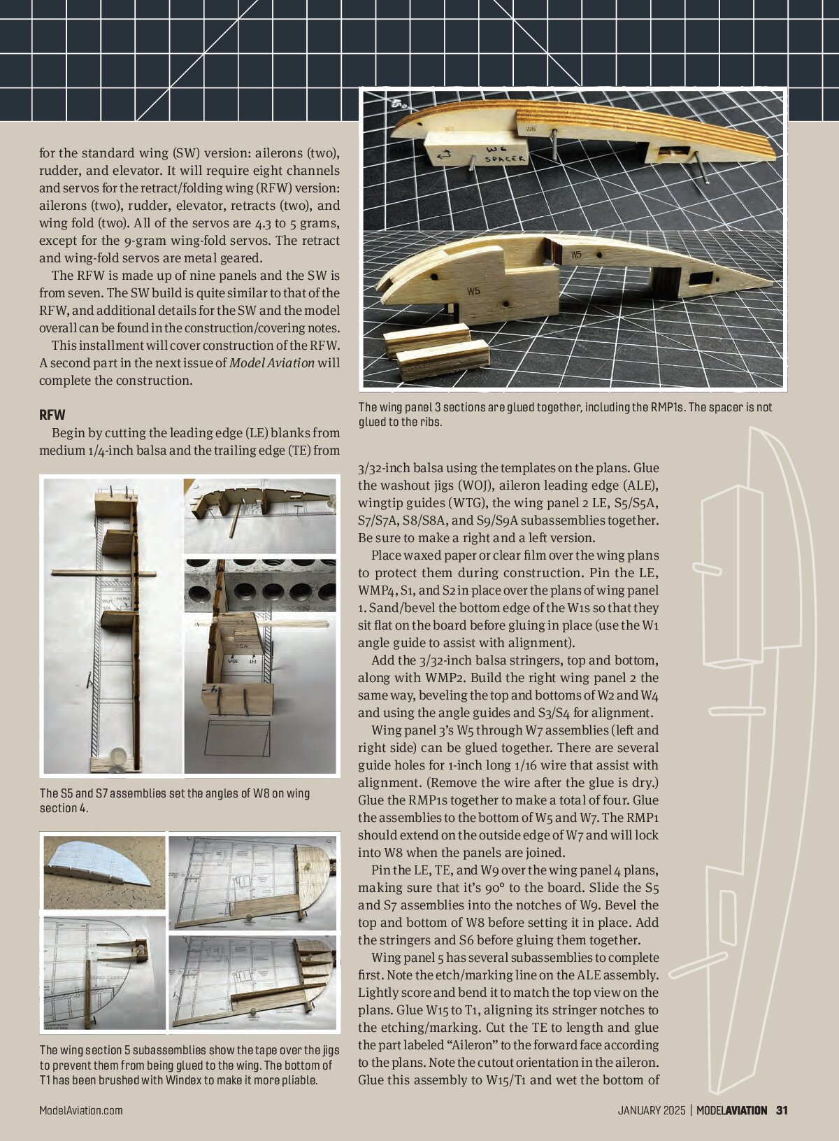
Wing panel 3’s W5 through W7 assemblies (left and right side) can be glued together. There are several guide holes for 1-inch long 1/16 wire that assist with alignment. (Remove the wire after the glue is dry.) Glue the RMP1s together to make a total of four. Glue the assemblies to the bottom of W5 and W7. The RMP1 should extend on the outside edge of W7 and will lock into W8 when the panels are joined.
Pin the LE, TE, and W9 over the wing panel 4 plans, making sure that it’s 90° to the board. Slide the S5 and S7 assemblies into the notches of W9. Bevel the top and bottom of W8 before setting it in place. Add the stringers and S6 before gluing them together.
Wing panel 5 has several subassemblies to complete first. Note the etch/marking line on the ALE assembly. Lightly score and bend it to match the top view on the plans. Glue W15 to T1, aligning its stringer notches to the etching/marking. Cut the TE to length and glue the part labeled “Aileron” to the forward face according to the plans. Note the cutout orientation in the aileron. Glue this assembly to W15/T1 and wet the bottom of


BUILD THE F4U-1A CORSAIR PARK FLYER


following the plans. Add T2 to T6 on the etching/markings on T1.
Glue the ALE assembly to be even with the forward face of the aileron before gluing W10 in place 90° to the board. Glue the LE to W10 and W15/T1. Place pins even with the forward face of ALE for spacing and slide WLP2 and S8 and S9 assemblies in place, along with the bottom stringers (noting that #2 is made from basswood). Glue everything in place when you are satisfied with the fit.
Insert WSMP into the slots in W11 and W12 and add this assembly, along with the remaining ribs (including W12A), before gluing. Add the top stringers. Make the aileron “ribs” from scrap 3/32-inch balsa and add the small block on the tip as shown on the plans. Remove the panel from the board and shape the aileron ribs and contour the TE and T1.
Tape wing panels 4 and 5 together and use tape to protect the ribs while shaping the LE with a block plane. Finish with 150-grit, 220-grit, and then 320-grit sandpaper. Templates on the plans will assist with the shape. Shape the top of wing panel 2’s LE the same way, but do not shape the bottom at this time. Cut the aileron

T1 with Windex and set aside.
Pin the WOJ and WTGs in place and place Scotch Magic Tape over the top of them both.
Place the TE/aileron/W15/T1 assembly in place over the plans, WOJ, and WTG. Pin T1 as needed so that it forms to the curve of WTG. Pin the TE

free on wing panel 5. Infill with scrap between the top and bottom #5 stringer in the aileron bay. Shape the aileron LE before cutting the slots according to the plans for the hinges, but do not glue them in place at this time. Build the left wing panels the same way and lightly sand the structure overall.
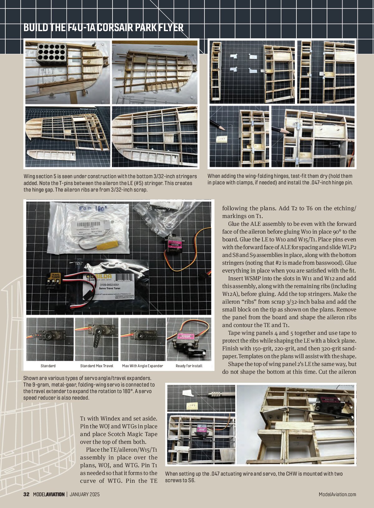
If you plan to add the folding wing to your model, the following steps are next. Test-fit 3D-printed hinge parts H1 to H3 into wing panels 4 and 5. Note their orientation. Adjust and trim the ribs and hinge tops as needed for the best fit. Make the .047-inch wire hinge pin from the plans template. Test-fit it into the hinges; the fit should be snug but not tight. Carefully drill it out if needed. (Do not overbore.)
Bevel the inside and top edges of W9 and W10 between the hinges to create a slot for the hinge pin. With the pin and hinges in place, test the wing fold, making small adjustments as needed. When satisfied with the movement, tack-glue the hinges in place, taking care not to glue the hinge halves together.
Remove the hinge pin and separate the wing panels before permanently gluing the hinges in place. Add the 1/8-inch light plywood scrap forward of the hinge between the top of W8 and W9. Following the plans, infill around the hinges with scrap material. Remove the cutout sections on W10 and W11, reinsert the hinge pin, and tape the bottom of wing panels 4 and 5 together.
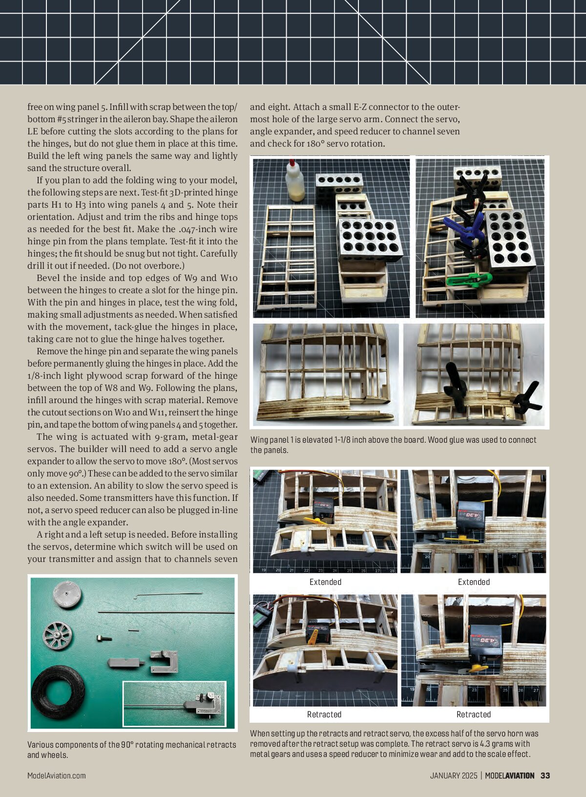
The wing is actuated with 9-gram, metal-gear servos. The builder will need to add a servo angle expander to allow the servo to move 180°. (Most servos only move 90°.) These can be added to the servo similar to an extension. An ability to slow the servo speed is also needed. Some transmitters have this function. If not, a servo speed reducer can also be plugged in-line with the angle expander.
A right and a left setup is needed. Before installing the servos, determine which switch will be used on your transmitter and assign that to channels seven and eight. Attach a small E-Z connector to the outer-most hole of the large servo arm. Connect the servo, angle expander, and speed reducer to channel seven and check for 180° servo rotation.

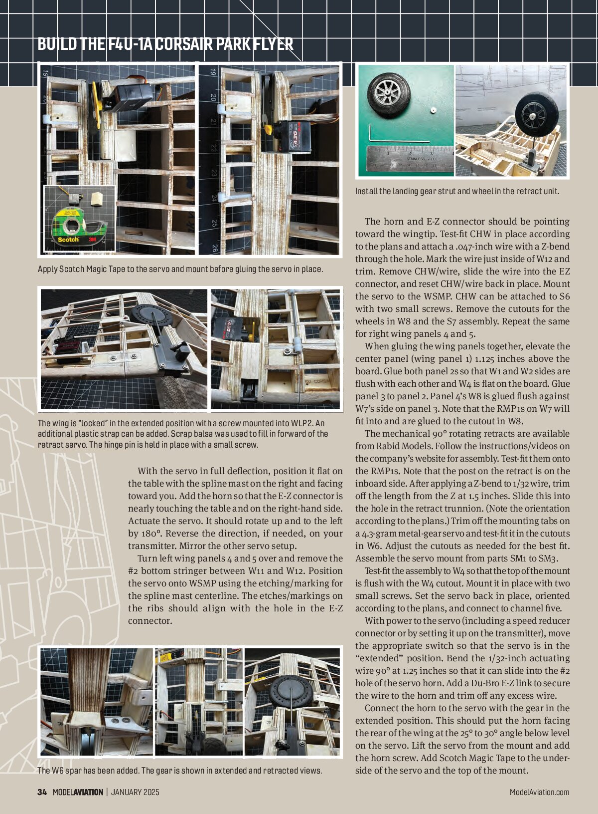
Wing panel 1 is elevated 1-1/8 inch above the board. Wood glue was used to connect the panels.

Various components of the 90° rotating mechanical retracts and wheels.

When setting up the retracts and retract servo, the excess half of the servo horn was removed after the retract setup was complete. The retract servo is 4.3 grams with metal gears and uses a speed reducer to minimize wear and add to the scale effect.
BUILD THE F4U-1A CORSAIR PARK FLYER

The wing is “locked” in the extended position with a screw mounted into WLP2. An additional plastic strap can be added. Scrap balsa was used to fill in forward of the retract servo. The hinge pin is held in place with a small screw.

The horn and E-Z connector should be pointing toward the wingtip. Test-fit CHW in place according to the plans and attach a .047-inch wire with a Z-bend through the hole. Mark the wire just inside of W12 and trim. Remove CHW/wire, slide the wire into the EZ connector, and reset CHW/wire back in place. Mount the servo to the WSMP. CHW can be attached to S6 with two small screws. Remove the cutouts for the wheels in W8 and the S7 assembly. Repeat the same for right wing panels 4 and 5.
When gluing the wing panels together, elevate the center panel (wing panel 1) 1.125 inches above the board. Glue both panel 2s so that W1 and W2 sides are flush with each other and W4 is flat on the board. Glue panel 3 to panel 2. Panel 4’s W8 is glued flush against W7’s side on panel 3. Note that the RMP1s on W7 will fit into and are glued to the cutout in W8.

With the servo in full deflection, position it flat on the table with the spline mast on the right and facing toward you. Add the horn so that the E-Z connector is nearly touching the table and on the right-hand side. Actuate the servo. It should rotate up and to the left by 180°. Reverse the direction, if needed, on your transmitter. Mirror the other servo setup.
Turn left wing panels 4 and 5 over and remove the #2 bottom stringer between W11 and W12. Position the servo onto WSMP using the etching/marking for the spline mast centerline. The etches/markings on the ribs should align with the hole in the E-Z connector.
The mechanical 90° rotating retracts are available from Rabid Models. Follow the instructions/videos on the company’s website for assembly. Test-fit them onto the RMP1s. Note that the post on the retract is on the inboard side. After applying a Z-bend to 1/32 wire, trim off the length from the Z at 1.5 inches. Slide this into the hole in the retract pin. (Note the orientation according to the plans.) Trim off the mounting tabs on a 4.3-gram metal-gear servo and test-fit it in the cutouts in W6. Adjust the cutouts as needed for the best fit. Assemble the servo mount from parts SM1 to SM3.
Test-fit the assembly to W6 so that the top of the mount is flush with the W4 cutout. Mount it in place with two small screws. Set the servo back in place, oriented according to the plans, and connect to channel five.
With power to the servo (including a speed reducer connector or by setting it up on the transmitter), move the appropriate switch so that the servo is in the “extended” position. Bend the 1/32-inch actuating wire 90° at 1.25 inches so that it can slide into the #2 hole of the Du-Bro E-Z link to secure the wire to the horn and trim off any excess wire. Connect the horn to the servo with the gear in the extended position. This should put the horn facing the rear of the wing at the 25° to 30° angle below level on the servo. Lift the servo from the mount and add the horn screw. Add Scotch Magic Tape to the underside of the servo and the top of the mount.


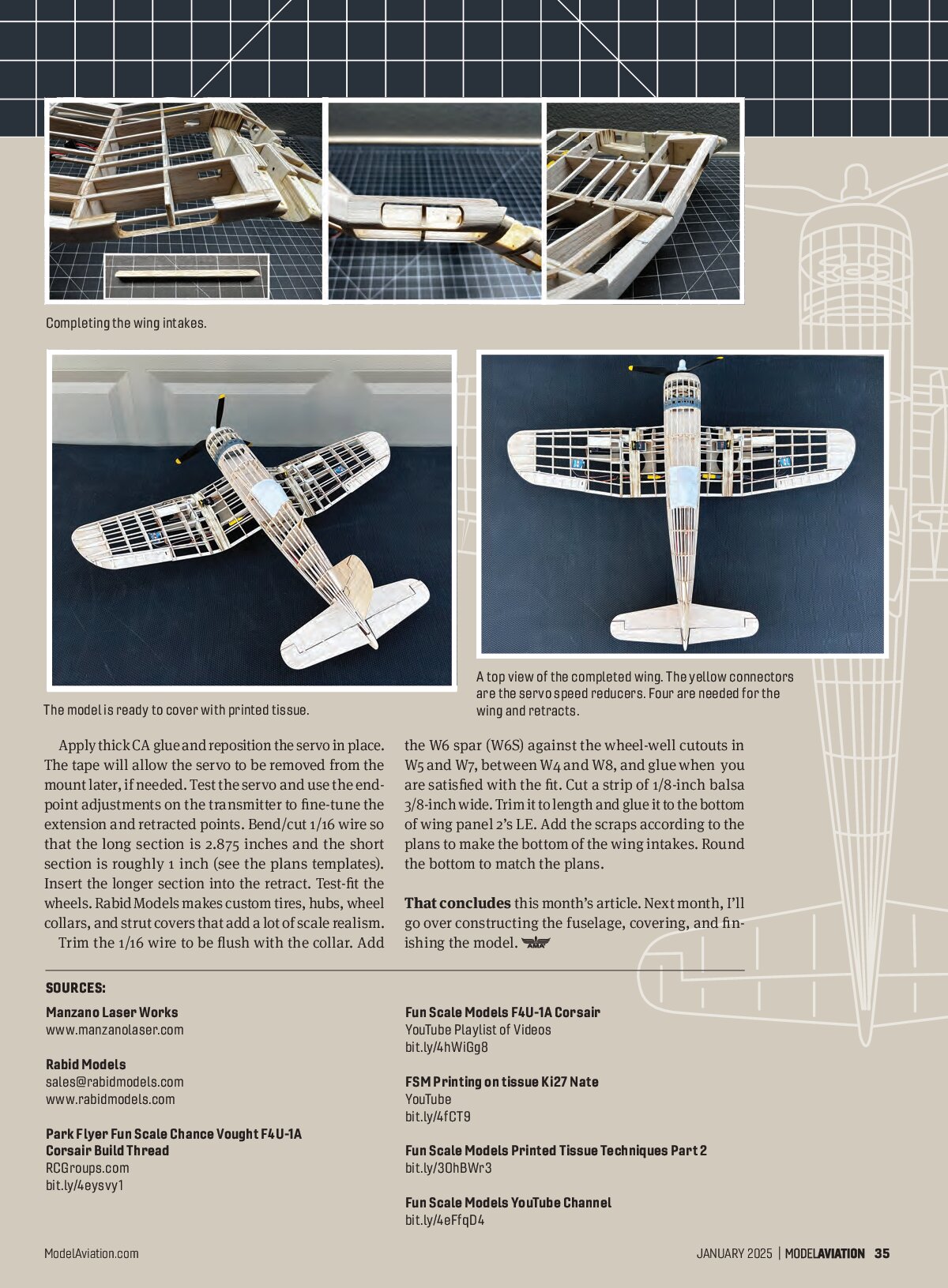
Completing the wing intakes.

The model is ready to cover with printed tissue.

A top view of the completed wing. The yellow connectors are the servo speed reducers. Four are needed for the wing and retracts.
Apply thick CA glue and reposition the servo in place. The tape will allow the servo to be removed from the mount later, if needed. Test the servo and use the end-point adjustments on the transmitter to fine-tune the extension and retracted points. Bend/cut 1/16 wire so that the long section is 2.875 inches and the short section is roughly 1 inch (see the plans templates). Insert the longer section into the retract. Test-fit the wheels. Rabid Models makes custom tires, hubs, wheel collars, and strut covers that add a lot of scale realism. Trim the 1/16 wire to be flush with the collar. Add the W6 spar (W6S) against the wheel-well cutouts in W5 and W7, between W4 and W8, and glue when you are satisfied with the fit. Cut a strip of 1/8-inch balsa 3/8-inch wide. Trim it to length and glue it to the bottom of wing panel 2’s LE. Add the scraps according to plans to make the bottom of the wing intakes. Round the bottom to match the plans.
That concludes this month’s article. Next month, I’ll go over constructing the fuselage, covering, and finishing the model.
SOURCES:
Manzano Laser Works
www.manzanolaser.com
Rabid Models
sales@rabidmodels.com
www.rabidmodels.com
Park Flyer Fun Scale Chance Vought F4U-1A Corsair Build Thread
RCGroups.com
bit.ly/4oysvy1
Fun Scale Models F4U-1A Corsair
YouTube Playlist of Videos
bit.ly/4hWiGg8
FSM Printing on tissue Ki27 Nate
YouTube
bit.ly/4fCT9
Fun Scale Models Printed Tissue Techniques Part 2
bit.ly/30hBWr3
Fun Scale Models YouTube Channel
bit.ly/4eFqD4