FLYING SAFELY: A FIRST-TIME FLIER’S GUIDE TO MODEL AVIATION
By Ashton Lewis, AMA Education Support Specialist | ashtonl@modelaircraft.org
WELCOME TO the exciting world of model aviation! If you’re a first-time flier, you’re about to embark on a thrilling journey. Before you take to the sky, it’s important to understand the rules and guidelines that ensure a safe and enjoyable experience. Here’s a step-by-step guide to help you get started and stay compliant.
Step 1: Register Your Aircraft
Before you can start flying, you need to register your model aircraft with the FAA. If your aircraft weighs more than 0.55 pounds (250 grams), head over to the FAA Drone Zone (https://faadronezone-access.faa.org) to complete the registration. Once registered, make sure to label your aircraft with the provided registration number. This step is crucial for accountability and safety.
Step 2: Take the TRUST Test
All recreational fliers must pass The Recreational UAS Safety Test (TRUST). This free online test covers basic safety and legal requirements. It’s quick and easy, and you can take it through an FAA-approved test administrator, such as AMA. Passing this test ensures that you understand the fundamental rules of flying.
Step 3: Join a CBO
Joining a community-based organization (CBO), such as AMA, provides numerous benefits. As a member, you’ll have access to resources, training, and flying sites. AMA also offers liability insurance and adheres to FAA safety guidelines, giving you peace of mind as you fly.
Step 4: Follow Safety Guidelines
Adhering to safety guidelines is essential. The AMA Safety Code includes important rules, such as maintaining visual line of sight, avoiding flying over people, and respecting no-fly zones. These rules are designed to keep you and others safe.
Step 5: Use Designated Flying Sites
Whenever possible, use AMA-designated flying fields. These sites are chosen for your safety and are suitable for model aircraft flying. Always check with the club officer or safety officer to ensure that your operations are permitted at the respective location.
Step 6: Preflight Checklist
Before each flight, inspect your aircraft for any damage or issues. Ensure that all components are secure and functioning properly. Also, check the weather conditions to make sure that it’s safe to fly. Avoid flying in high wind, rain, or other adverse conditions.
Step 7: Obtain Airspace Authorization
If you plan to fly within controlled airspace, you must first obtain FAA authorization through Low Altitude Authorization and Notification Capability (LAANC). This helps prevent any potential conflicts with manned aircraft and ensures a safe flying environment.
Step 8: Respect Privacy and Property
Always respect the privacy of others and avoid flying over private property without permission. Be mindful of public spaces and avoid flying over crowds or events. This consideration helps maintain a positive image of the model aviation community.
Step 9: Stay Informed
Laws can change, so it’s important to stay updated on any new rules or guidelines. The AMA and FAA websites are excellent resources for the latest information. Staying informed ensures that you remain compliant and can continue to enjoy the hobby without any issues.
Ready to Fly?
By following these steps, you will be well-prepared to enjoy the thrill of model aviation safely and responsibly. Remember, the key to a great flying experience is not just skill but also adherence to safety and regulatory guidelines. So, get your aircraft ready, join a local club, and take to the sky with confidence. Happy flying!
site can operate without the need to broadcast Remote ID information.
To apply for FRIA recognition, reach out to FRIA@modelaircraft.org.
3. Authorization to Exempt Remote ID
Both sanctioned and unsanctioned events can be held at a flying site that has been granted an authorization that exempts the Remote ID requirement for daily operations, including events. This exemption essentially provides the same type of Remote ID relief as a FRIA but without a FRIA designation to the club site.
If your club site is on or near airport property, reach out to lucasr@modelaircraft.org to begin the Remote ID exemption process.
Altitude Exemptions
There are a few options for AMA events to operate at higher altitudes.
1. National Altitude Authorization Waiver
Sanctioned AMA events within uncontrolled airspace are eligible for an altitude waiver under the National Authorization. This waiver grants authorization to fly up to the upper threshold of Class G airspace—either 700 or 1,200 feet above ground level. Which altitude your sanctioned event can receive depends on your specific location in relation to controlled airspace.
The CD or EM is required to request a NOTAM to obtain an FAA altitude waiver.
2. LOA/7711-1
Sanctioned and unsanctioned AMA events can operate at a flying site with an existing letter of agreement (LOA)/7711-1 that grants them the ability to fly at a previously established higher altitude for day-to-day operations, as well as events.
3. Airspace Authorization
Sanctioned events being held within controlled airspace might be eligible to receive an airspace authorization for an altitude higher than permitted on the FAA UAS Facility Map. Contact amagov@modelaircraft.org to request the authorization for a specific altitude for the duration of your event.
AMA wants to make sure that our events are enjoyable and reduce burdens when possible. We are consistently working with the FAA to further reduce Remote ID requirements for our members and events, as well as finding ways to increase altitude limits for sites in both controlled and uncontrolled airspace. If you have any further questions regarding Remote ID and altitude waivers, please visit the AMA Government Affairs blog or contact amagov@modelaircraft.org.
CRAIG BRADLEY (1950-2024)
CRAIG BRADLEY, born on October 2, 1950, in Grand Rapids, Michigan, passed away on September 10, 2024, at the age of 73.
Craig was a vital contributor to AMA and the hobby of model aviation as a whole. Throughout his life, he dedicated 30-plus years to the RC helicopter community. His involvement included serving as a contest director (CD), a Fédération Aéronautique Internationale/F3C judge, event director (ED), and more. More specifically, Craig was a CD for the FAI/F3C World Championships for RC Model Helicopters and was the ED for the AMA RC Helicopter Nats.
In addition to partaking in the hobby of model aviation, Craig enjoyed restoring cars; playing, fixing, and building guitars; birdwatching; and stargazing. His working career consisted of 46 years of employment at NAPA, during which he was presented with various awards and certifications for his impressive work.
In addition to receiving bountiful recognition for his employment, Craig received various awards related to his participation in the hobby of model aviation, including an AMA President’s Award, an International Radio Controlled Helicopter Association Service Award, an AMA Award of Appreciation, and various awards and recognitions for his impressive performance in RC helicopter competition.

Craig is survived by his wife of 48 years, Karen; his two children, Sean and Joel; five grandchildren; two sisters; and various aunts, uncles, cousins, nieces, and nephews. He was referred to as a pillar of strength for his family, and he will be missed by all.
History Preserved
RECREATING WINGS OF THE PAST
By Terry Hreno, National Model Aviation Museum Volunteer
EXPLORING HISTORY can be fascinating. Archaeologists get clues from ancient dinosaur bones, bits of broken pottery, and ancient manuscripts. A person challenged with building museum replicas of model airplanes from more than 100 years ago faces similar challenges. A modeler’s tools are not picks and shovels. Clues come from digging through library archives and examining old models.
I have been asked by the National Model Aviation Museum on several occasions to build aircraft for the collection. The first question is, “How do you go about building one of these models?” A 1911 construction article advised the modeler to use the usual construction methods. That was the first clue that building historic replicas would be an adventure.
When model aviation first gained popularity more than a century ago, magazines were starting to feature aviation articles. Aeromodeling clubs were formed and resources were becoming available to modelers.
Modelers knew the usual construction methods in the early 1900s. We know the usual construction methods and materials used today. However, things have changed. A 1941 book on model ship building suggested using hot glue. Before you say you’ve used hot glue on a project, let’s do some research. That glue gun that we know and love wasn’t around until the 1950s, so in the 1930s, hot glue would have referred to an animal-hide glue that was heated and applied with a brush.
The answer to that question is to read carefully, avoid jumping to conclusions, and carefully examine pictures and patents!
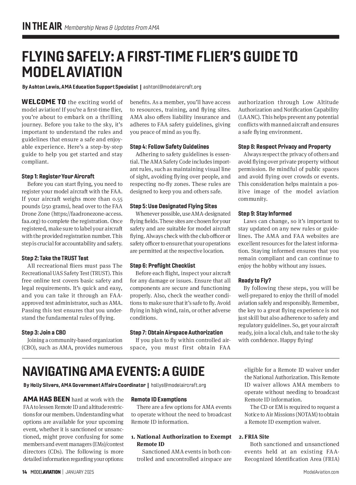
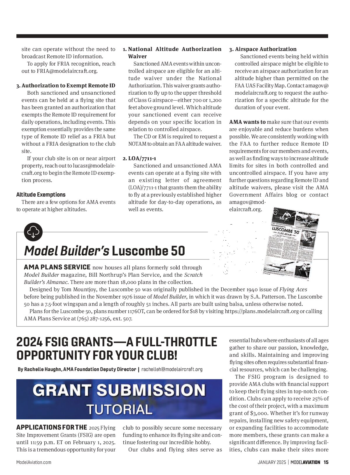
My latest museum challenges were two small, rubber-powered Free Flight aircraft—a contrarotating propeller model by William Martin, circa 1886, and a 1909 record-setting model by Percy Pierce.
AMA Thanks Its Lifetime Supporters!
The Academy of Model Aeronautics recently welcomed Life Members Thomas E. Norell, Centennial CO; Randy D. Adams, Fairfield OH; Lt. Col. Daniel Rees, Weston MO; Ben Saraceno, Long Beach CA; and Andre F. Torres, Hollister CA.
For information about becoming a Life Member, contact AMA Headquarters at (765) 287-1256, ext. 129.
—AMA Membership department


The Model Designers
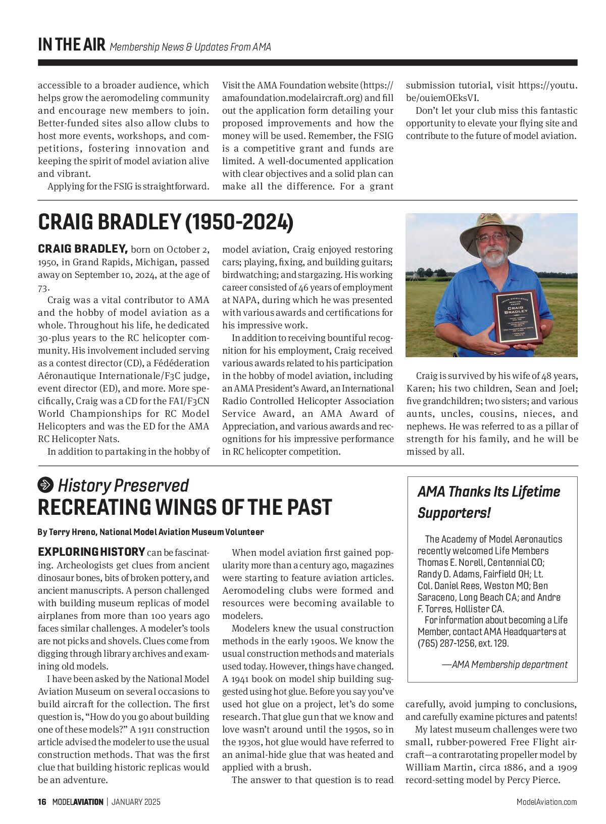
William was a farmer, self-taught engineer, inventor, and Stark County, Ohio, surveyor. His interest turned to flight in the 1880s, when he won a debate on the topic “Resolved that man will fly” with the Brush College debating society. Model aircraft experiments followed, and in 1908, he built a full-scale glider.
The family horse pulled the glider aloft on the first flight to an altitude of 20 feet. The glider would make more than 100 flights, with the horse later replaced by a car. Its last flight was at the Morris Park Racecourse in New York City, in 1909. Today, the glider is on display at the MAPS Air Museum in North Canton, Ohio.
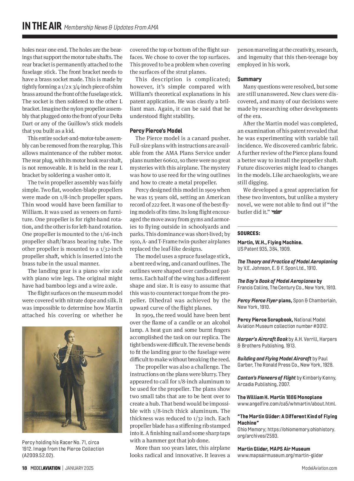
Percy began aeromodeling in the early 1900s as a member of possibly the first model airplane club in the US, the Junior Aero Club of the United States. He would go on to set numerous US and world model airplane records, publish and kit model designs, write aeromodeling articles for Aeronautics magazine, and edit Fly magazine. In 1936, he was one of the original signatories to the document that founded AMA.
William Martin’s Model
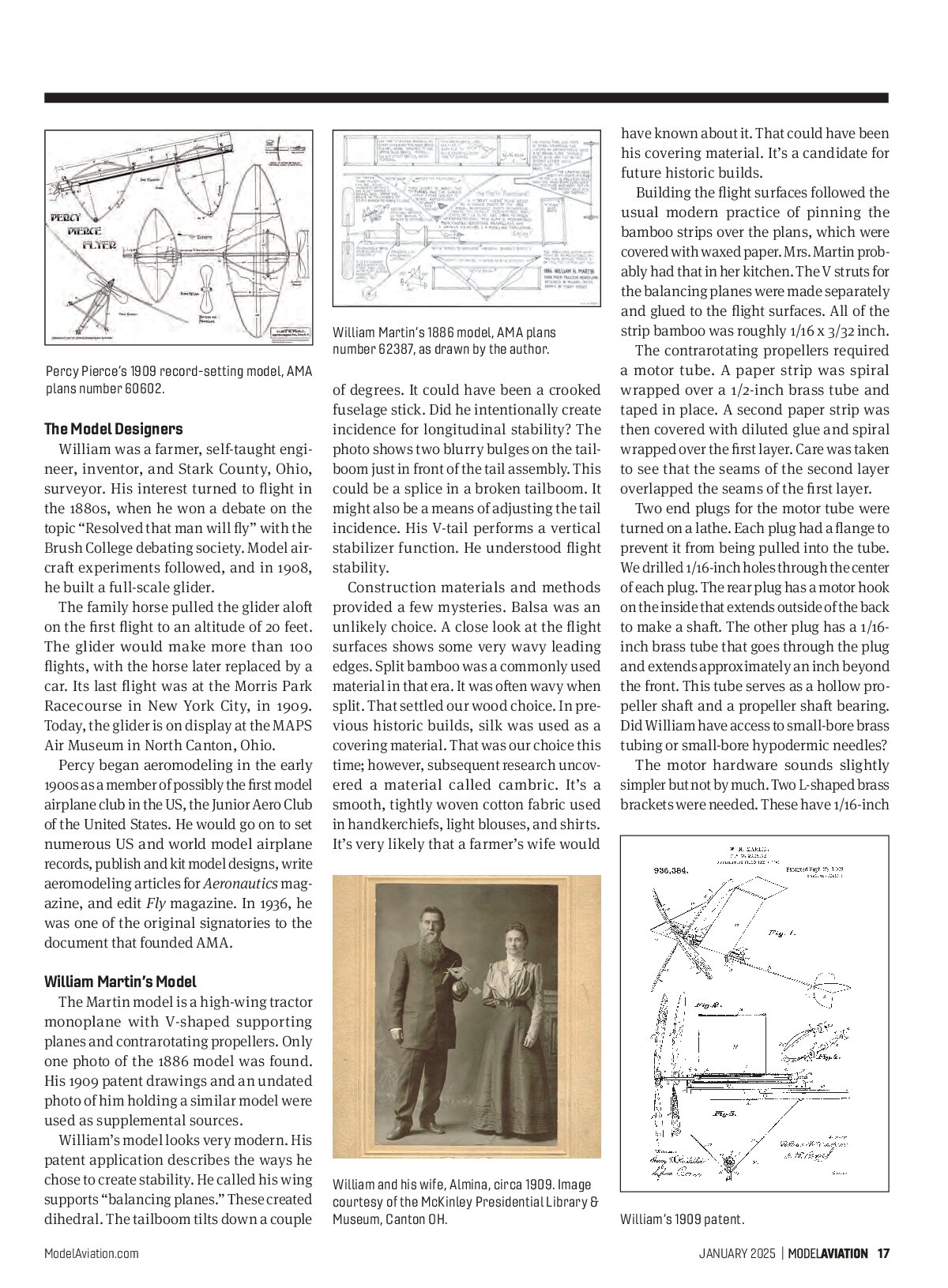
The Martin model is a high-wing tractor monoplane with V-shaped supporting planes and contrarotating propellers. Only one photo of the 1886 model was found. His 1909 patent drawings and an undated photo of him holding a similar model were used as supplemental sources.
William’s model looks very modern. His patent application describes the ways he chose to create stability. He called his wing supports “balancing planes.” These created dihedral. The tailboom tilts down a couple of degrees. It could have been a crooked fuselage stick. Did he intentionally create incidence for longitudinal stability? The photo shows two blurry bulges on the tailboom just in front of the tail assembly. This could be a splice in a broken tailboom. It might also be a means of adjusting the tail incidence. His V-tail performs a vertical stabilizer function. He understood flight stability.
Construction materials and methods provided a few mysteries. Balsa was an unlikely choice. A close look at the flight surfaces shows some very wavy leading edges. Split bamboo was a commonly used material in that era. It was often wavy when split. That settled our wood choice. In previous historic builds, silk was used as a covering material. That was our choice this time; however, subsequent research uncovered a material called cambric. It’s a smooth, tightly woven cotton fabric used in handkerchiefs, light blouses, and shirts. It’s very likely that a farmer’s wife would have known about it. That could have been his covering material. It’s a candidate for future historic builds.

Building the flight surfaces followed the usual modern practice of pinning the bamboo strips over the plans, which were covered with waxed paper. Mrs. Martin probably had that in her kitchen. The V struts for the balancing planes were made separately and glued to the flight surfaces. All of the strip bamboo was roughly 1/16 x 3/32 inch.
The contrarotating propellers required a motor tube. A paper strip was spiral wrapped over a 1/2-inch brass tube and taped in place. A second paper strip was then covered with diluted glue and spiral wrapped over the first layer. Care was taken to see that the seams of the second layer overlapped the seams of the first layer.
Two end plugs for the motor tube were turned on a lathe. Each plug had a flange to prevent it from being pulled into the tube. We drilled 1/16-inch holes through the center of each plug. The rear plug has a motor hook on the inside that extends outside of the back to make a shaft. The other plug has a 1/16-inch brass tube that goes through the plug and extends approximately an inch beyond the front. This tube serves as a hollow propeller shaft and a propeller shaft bearing. Did William have access to small-bore brass tubing or small-bore hypodermic needles?
The motor hardware sounds slightly simpler but not by much. Two L-shaped brass brackets were needed. These have 1/16-inch

holes near one end. The holes are the bearings that support the motor tube shafts. The rear bracket is permanently attached to the fuselage stick. The front bracket needs to have a brass socket made. This is made by tightly forming a 1/2 x 3/4-inch piece of shim brass around the front of the fuselage stick. The socket is then soldered to the other L bracket. Imagine the nylon propeller assembly that plugged onto the front of your Delta Dart or any of the Guillows’ stick models that you built as a kid.
This entire socket-and-motor-tube assembly can be removed from the rear plug. This allows maintenance of the rubber motor. The rear plug, with its motor hook rear shaft, is not removeable. It is held in the rear L bracket by soldering a washer onto it.
The twin propeller assembly was fairly simple. Two flat, wooden-blade propellers were made on 1/8-inch propeller spars. Thin wood would have been familiar to William. It was used as veneers on furniture. One propeller is for right-hand rotation, and the other is for left-hand rotation. One propeller is mounted to the 1/16-inch propeller shaft/brass bearing tube. The other propeller is mounted to a 1/32-inch propeller shaft, which is inserted into the brass tube in the usual manner.
The landing gear is a piano wire axle with piano wire legs. The original might have had bamboo legs and a wire axle.
The flight surfaces on the museum model were covered with nitrate dope and silk. It was impossible to determine how Martin attached his covering or whether he

covered the top or bottom of the flight surfaces. We chose to cover the top surfaces. This proved to be a problem when covering the surfaces of the strut planes.
This description is complicated; however, it’s simple compared with William’s theoretical explanations in his patent application. He was clearly a brilliant man. Again, it can be said that he understood flight stability.
Percy Pierce’s Model
The Pierce model is a canard pusher. Full-size plans with instructions are available from the AMA Plans Service under plans number 6602, so there were no great mysteries with this airplane. The mystery was how to use reed for the wing outlines and how to create a metal propeller.
Percy designed this model in 1909 when he was 15 years old, setting an American record of 222 feet. It was one of the best-flying models of its time. Its long flight encouraged the move away from gyms and armories to flying outside in schoolyards and parks. This dominance was short-lived; by 1910, A- and T-Frame twin-pusher airplanes replaced the leaf-like designs.
The model uses a spruce fuselage stick, a bent reed wing, and canard outlines. The outlines were shaped over cardboard patterns. Each half of the wing has a different shape and size. It is easy to assume that this was to counteract torque from the propeller. Dihedral was achieved by the upward curve of the flight planes.
In 1909, the reed would have been bent over the flame of a candle or an alcohol lamp. A heat gun and some burnt fingers accomplished the task on our replica. The tight bends were difficult. The reverse bends to fit the landing gear to the fuselage were difficult to make without breaking the reed.
The propeller was also a challenge. The instructions on the plans were blurry. They appeared to call for 1/8-inch aluminum to be used for the propeller. The plans show two small tabs that are to be bent over to create a hub. That bend would be impossible with 1/8-inch thick aluminum. The thickness was reduced to 1/32 inch. Each propeller blade has a stiffening rib stamped into it. A finishing nail and some sharp taps with a hammer got that job done.
More than 100 years later, this airplane looks radical and innovative. It leaves a person marveling at the creativity, research, and ingenuity that this then-teenage boy employed in his work.
Summary
Many questions were resolved, but some are still unanswered. New clues were discovered, and many of our decisions were made by researching other developments of the era.
After the Martin model was completed, an examination of his patent revealed that he was experimenting with variable tail incidence. We discovered cambric fabric. A further review of the Pierce plans found a better way to install the propeller shaft. Future discoveries might lead to changes in the models. Like archaeologists, we are still digging.
We developed a great appreciation for these two inventors, but unlike a mystery novel, we were not able to find out if “the butler did it.”
SOURCES:
Martin, W.H., Flying Machine.
US Patent 935, 384, 1909.
The Theory and Practice of Model Aeroplaning
by V.E. Johnson, E. & F. Spon Ltd., 1910.
The Boy’s Book of Model Aeroplanes by Francis Collins, The Century Co., New York, 1910.
Percy Pierce Flyer plans. Spon & Chamberlain, New York, 1910.
Percy Pierce Scrapbook. National Model Aviation Museum collection number #0012.
Harper’s Aircraft Book by A.H. Verrill, Harpers & Brothers Publishing, 1913.
Building and Flying Model Aircraft by Paul Garber, The Ronald Press Co., New York, 1928.
Canton’s Pioneers of Flight by Kimberly Kenny, Arcadia Publishing, 2007.
The William H. Martin 1886 Monoplane
www.angelfire.com/ca5/whmartin/about.html.
“The Martin Glider: A Different Kind of Flying Machine”
Ohio Memory; https://ohiomemory.ohiohistory.org/archives/2593.
Martin Glider, MAPS Air Museum
www.mapsairmuseum.org/martin-glider