CONTROL LINE NAVY CARRIER

NEW PRODUCTS; LINE SLIDER IDEA
By Dick Perry | tailhooker@comcast.net
THIS MONTH’S TOPICS include some new products of potential interest to Control Line (CL) Navy Carrier modelers. Actually, one is nearly new and the other is in development.
Also included is a useful means of controlling the in-flight position of the leadouts on the wing of Navy Carrier models. All have the potential to help simplify the building and flying activities of Carrier modelers by offering commercially available alternatives to making something yourself.
Electric Motor Mounts
The mounting of internal-combustion engines on Carrier models has been relatively standard since the beginning of the event. Beam-mounting is the accepted method, and positioning the engine for balance or putting the propeller or spinner where you want it is done by moving the engine forward or back on the parallel beam mounts.
The conversion of existing internal-combustion models to electric power usually involves fabricating an adapter that attaches to the existing beam mounts. Depending on what engine is being replaced with an electric motor, the added weight of an adapter might be necessary for balance, but a lighter conversion can be had with a firewall type of mount, with the extended beam mounts removed.
Converting an RC ARF model for CL Navy Carrier competition usually requires a significant change in output of the motor and, with it, the physical dimensions of the electric motor. Most models will have some type of firewall mounting for the original electric motor.
Usually, some type of spacer is necessary to adapt the new motor to the model. We normally end up fabricating the spacer.
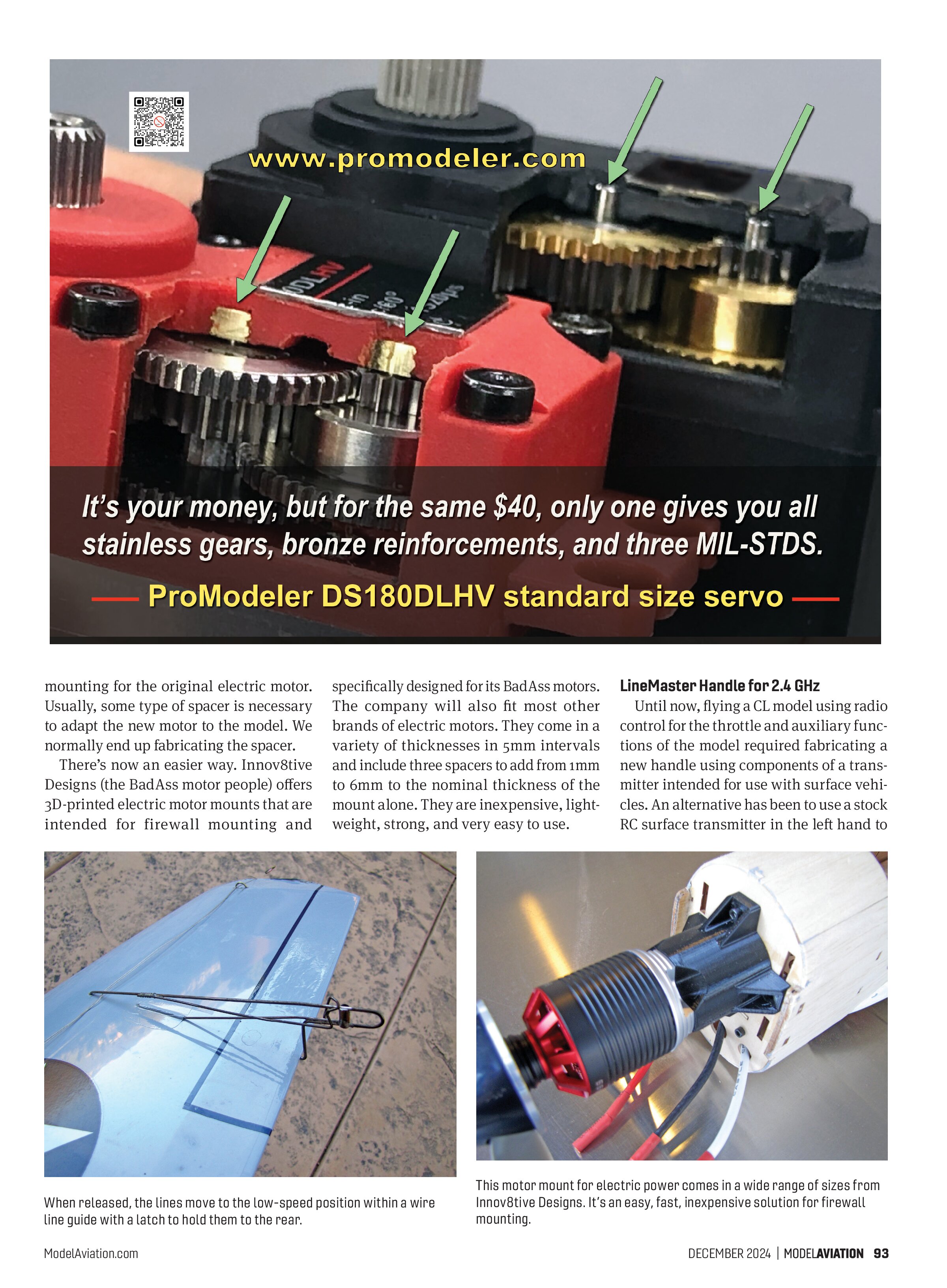
There’s now an easier way. Innov8tive Designs (the BadAss motor people) offers 3D-printed electric motor mounts that are intended for firewall mounting and specifically designed for its BadAss motors. The company will also fit most other brands of electric motors. They come in a variety of thicknesses in 5mm intervals and include three spacers to add from 1mm to 6mm to the nominal thickness of the mount alone. They are inexpensive, lightweight, strong, and very easy to use.
LineMaster Handle for 2.4 GHz
Until now, flying a CL model using radio control for the throttle and auxiliary functions of the model required fabricating a new handle using components of a transmitter intended for use with surface vehicles. An alternative has been to use a stock RC surface transmitter in the left hand to


control the throttle and a conventional two-line CL handle in the right hand to control the elevator. Auxiliary functions are limited with such a setup because both hands are occupied. It is also awkward for some modelers, and it’s a significant change from the way that we learned to fly with the original three-line Roberts and G-S systems.
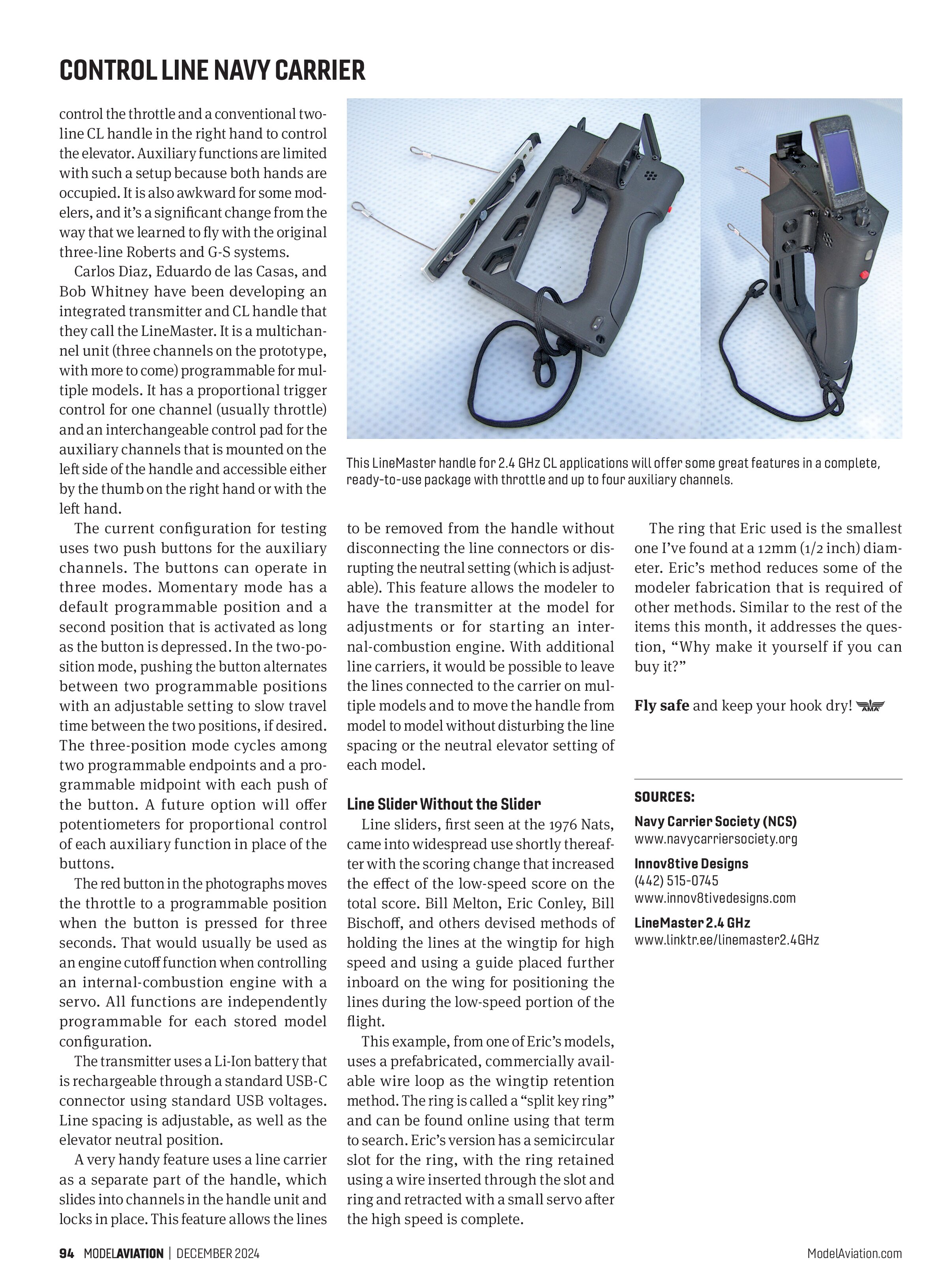
Carlos Diaz, Eduardo de las Casas, and Bob Whitney have been developing an integrated transmitter and CL handle that they call the LineMaster. It is a multichannel unit (three channels on the prototype, with more to come) programmable for multiple models. It has a proportional trigger control for one channel (usually throttle) and an interchangeable control pad for the auxiliary channels that is mounted on the left side of the handle and accessible either by the thumb on the right hand or with the left hand.
The current configuration for testing uses two push buttons for the auxiliary channels. The buttons can operate in three modes. Momentary mode has a default programmable position and a second position that is activated as long as the button is depressed. In the two-position mode, pushing the button alternates between two programmable positions with an adjustable setting to slow travel time between the two positions, if desired. The three-position mode cycles among two programmable endpoints and a programmable midpoint with each push of the button. A future option will offer potentiometers for proportional control of each auxiliary function in place of the buttons.
The red button in the photographs moves the throttle to a programmable position when the button is pressed for three seconds. That would usually be used as an engine cutoff function when controlling an internal-combustion engine with a servo. All functions are independently programmable for each stored model configuration.
The transmitter uses a Li-Ion battery that is rechargeable through a standard USB-C connector using standard USB voltages. Line spacing is adjustable, as well as the elevator neutral position.
A very handy feature uses a line carrier as a separate part of the handle, which slides into channels in the handle unit and locks in place. This feature allows the lines to be removed from the handle without disconnecting the line connectors or disrupting the neutral setting (which is adjustable). This feature allows the modeler to have the transmitter at the model for adjustments or for starting an internal-combustion engine. With additional line carriers, it would be possible to leave the lines connected to the carrier on multiple models and to move the handle from model to model without disturbing the line spacing or the neutral elevator setting of each model.

Line Slider Without the Slider
Line sliders, first seen at the 1976 Nats, came into widespread use shortly thereafter with the scoring change that increased the effect of the low-speed score on the total score. Bill Melton, Eric Conley, Bill Bischoff, and others devised methods of holding the lines at the wingtip for high speed and using a guide placed further inboard on the wing for positioning the lines during the low-speed portion of the flight.
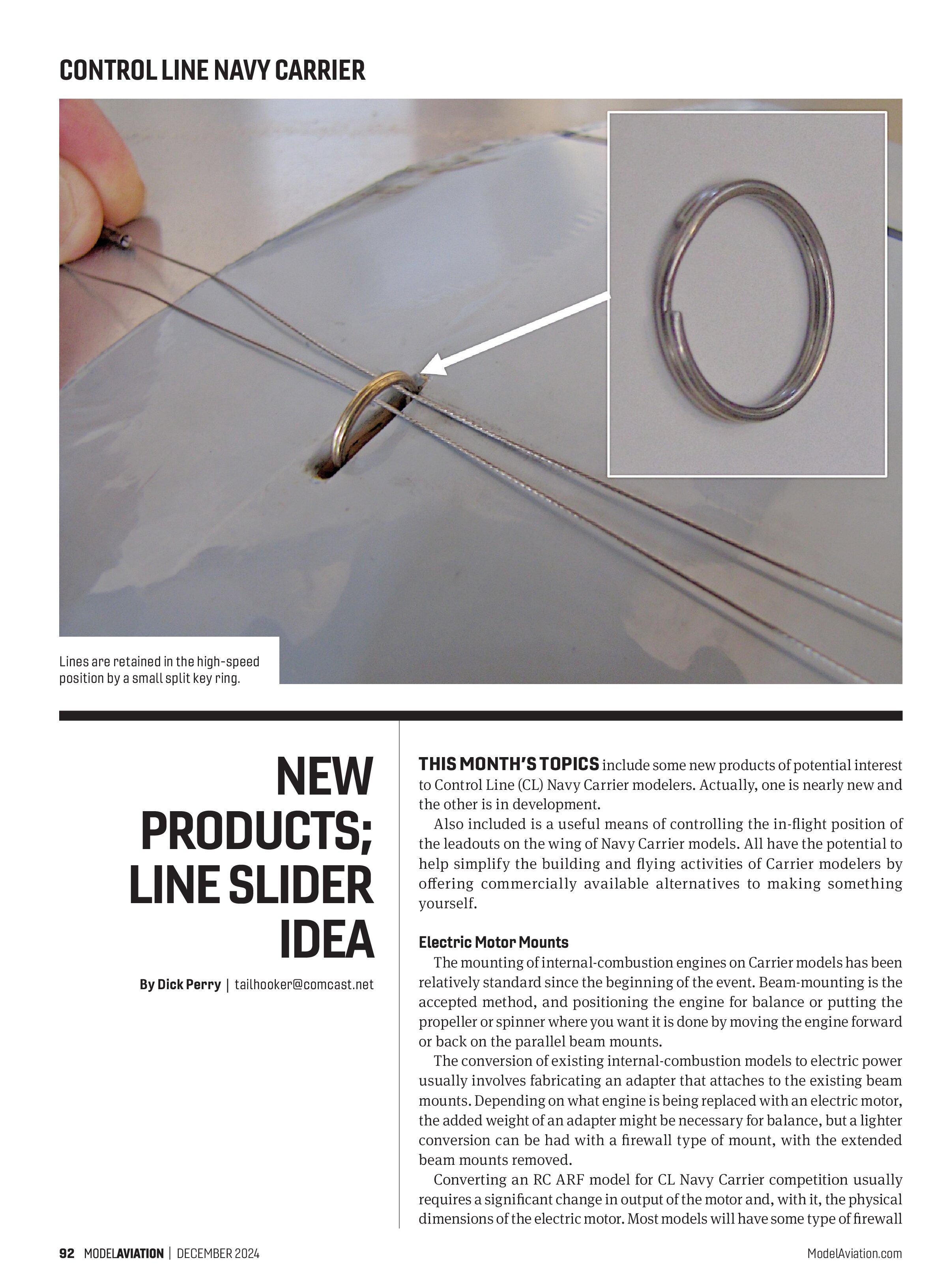
This example, from one of Eric’s models, uses a prefabricated, commercially available wire loop as the wingtip retention method. The ring is called a “split key ring” and can be found online using that term to search. Eric’s version has a semicircular slot for the ring, with the ring retained using a wire inserted through the slot and ring and retracted with a small servo after the high speed is complete.
The ring that Eric used is the smallest one I’ve found at a 12mm (1/2 inch) diameter. Eric’s method reduces some of the modeler fabrication that is required of other methods. Similar to the rest of the items this month, it addresses the question, “Why make it yourself if you can buy it?”
Fly safe and keep your hook dry!
SOURCES:
Navy Carrier Society (NCS)
www.navycarriersociety.org
Innov8tive Designs
(442) 515-0745
www.innov8tivedesigns.com
LineMaster 2.4 GHz
www.linktr.ee/linemaster2.4GHz