America’s Early Free-Flight Models
Augustus Herring and his auto-stabilized rubber- and gas-powered models
By C. David Gierke cdavidgierke@gmail.com Photos provided by the author
For aviation enthusiasts, December 17, 1903, has a special meaning. The date, of course, represents when the Wright brothers first flew their manned, powered, heavier-than-air machine at Kitty Hawk, North Carolina.
Eleven months earlier (January 3, 1903), on a snow-laden farm field in rural Michigan, another pioneer experimenter, Augustus M. Herring, successfully flew the world’s first internal-combustion-engine-powered free-flight model aeroplane.
At first glance, Herring’s relatively obscure achievement paled in importance to the Wrights’ feat. However, this is just the beginning of the story. His gas-powered model gave him something that the Wrights didn’t have—a working, demonstrable machine—which is what the U.S. Patent Office demanded.
Had Herring been able to pursue his prior application (1898), along with that of his 1903 machine, rather than suggest that he and the Wrights form a commercial aeroplane company, historians might be recalling a more favorable account of America’s emerging aeroplane industry. I’ll share more about this later.
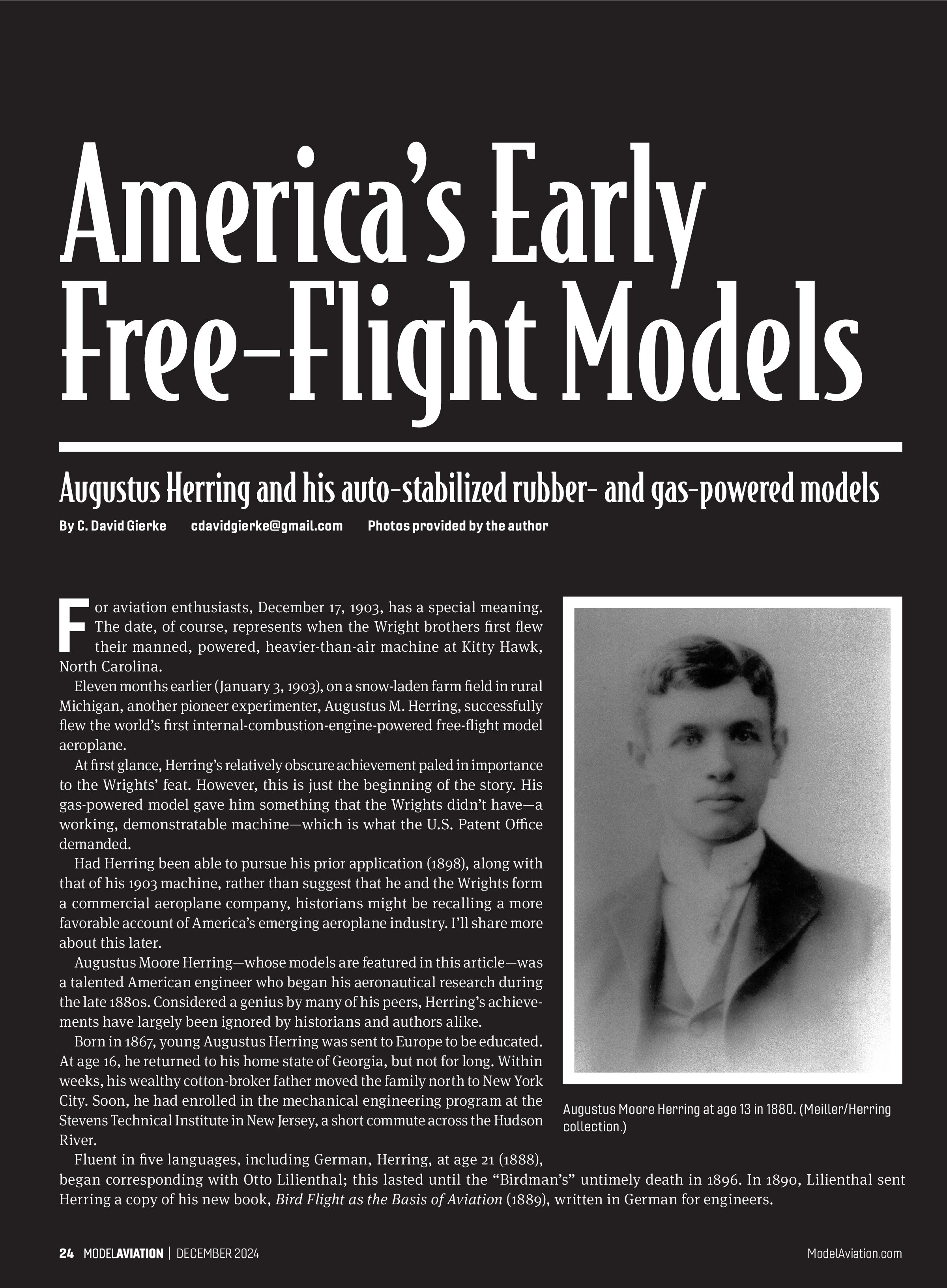
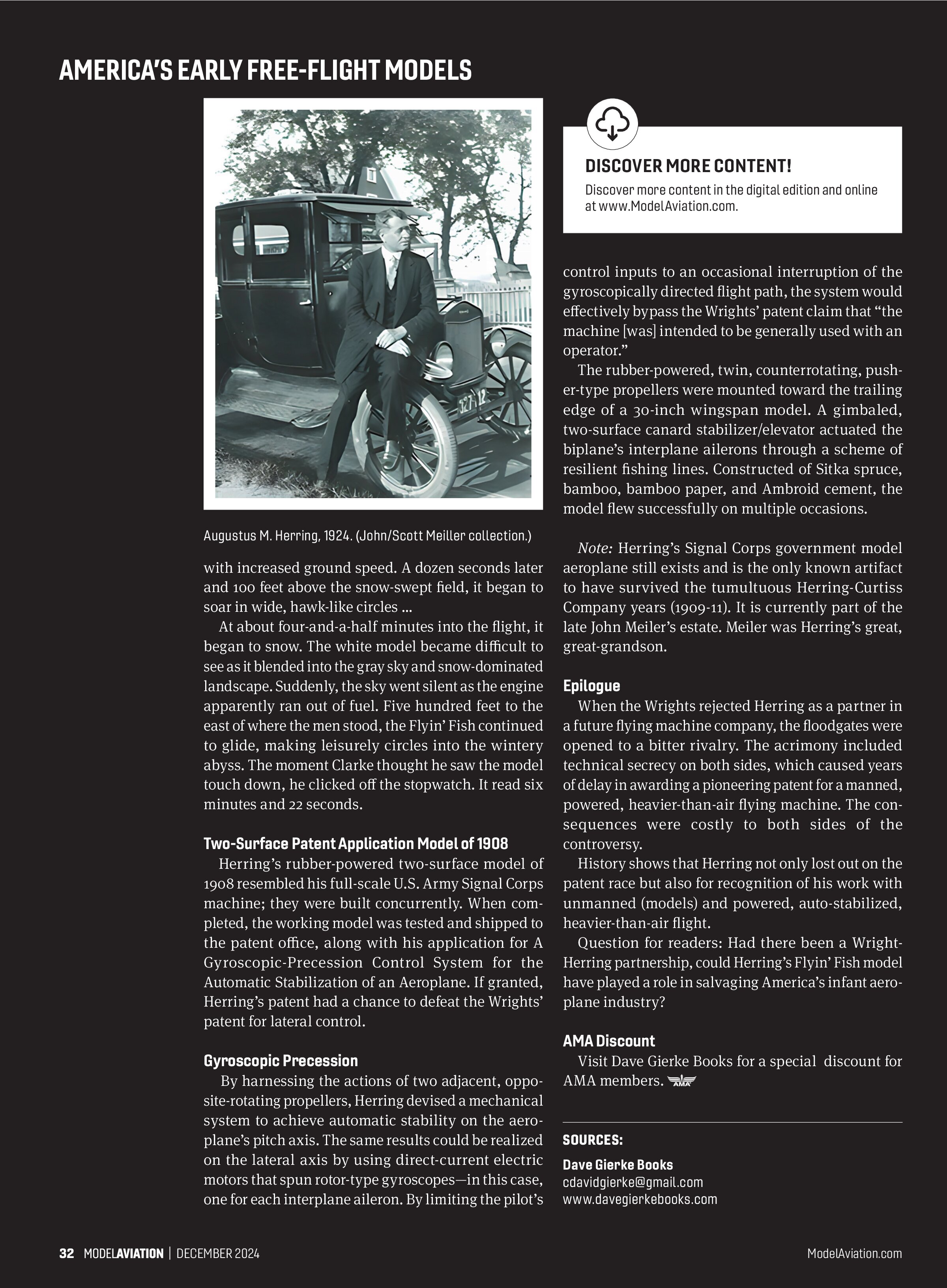
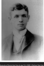
Augustus Moore Herring—whose models are featured in this article—was a talented American engineer who began his aeronautical research during the late 1880s. Considered a genius by many of his peers, Herring’s achievements have largely been ignored by historians and authors alike.
Born in 1867, young Augustus Herring was sent to Europe to be educated. At age 16, he returned to his home state of Georgia, but not for long. Within weeks, his wealthy cotton-broker father moved the family north to New York City. Soon, he had enrolled in the mechanical engineering program at the Stevens Technical Institute in New Jersey, a short commute across the Hudson River.
Fluent in five languages, including German, Herring, at age 21 (1888), began corresponding with Otto Lilienthal; this lasted until the “Birdman’s” untimely death in 1896. In 1890, Lilienthal sent Herring a copy of his new book, Bird Flight as the Basis of Aviation (1889), written in German for engineers.
Herring pored over its contents, from which he learned the basics of flight, including how to calculate the lift generated by a wing. It was not long before the two friends were engaged in related technical correspondence, including the merits of Herring’s free-flight models.
Tandem-Wing Glider Model (1891)
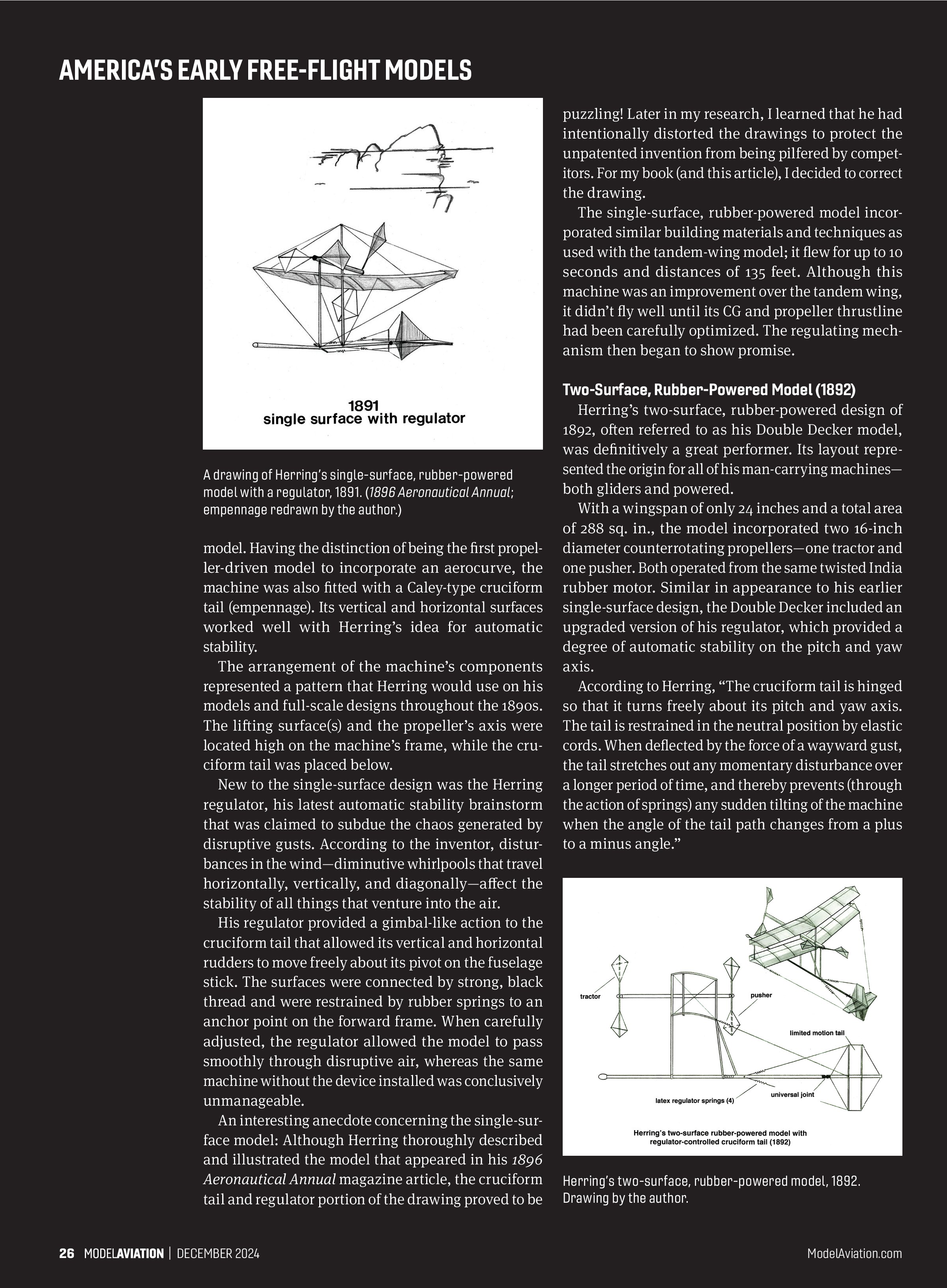
After some preliminary work with a single-surface design, Herring decided to proceed with a more familiar configuration—a tandem-wing glider, which incorporated dihedral for lateral stability. It was made principally of bamboo strips trussed between king posts on each wing with low-stretch fishing line. With wingspans of 30 inches, the 5-inch arc-type aerocurve (his word for a curved airfoil) ribs were covered with lightweight bamboo paper and sealed with a shellac-like substance.

From previous experience, Herring noted that even the best of his models had difficulty maintaining their equilibrium in rough air conditions. He observed that since the air is rarely at rest, nor does it move in a smooth stream or stay at the same speed for long, a flying machine’s (model or full-scale) attempt to navigate these disturbances is plagued with wild fore and aft movements of its center of pressure as it bounces about.
Ideally, he reasoned, the center of pressure and the center of gravity (CG) should be maintained at the same point on the chord of the lifting surface(s); otherwise, there will be a loss of equilibrium, resulting in unintended climbs and dives. To Herring, his challenge was to control the center of pressure movement on a model through automatic stability. Later, his full-scale, man-carrying machines used a combination of an automatic stability device and pilot weight-shifting.
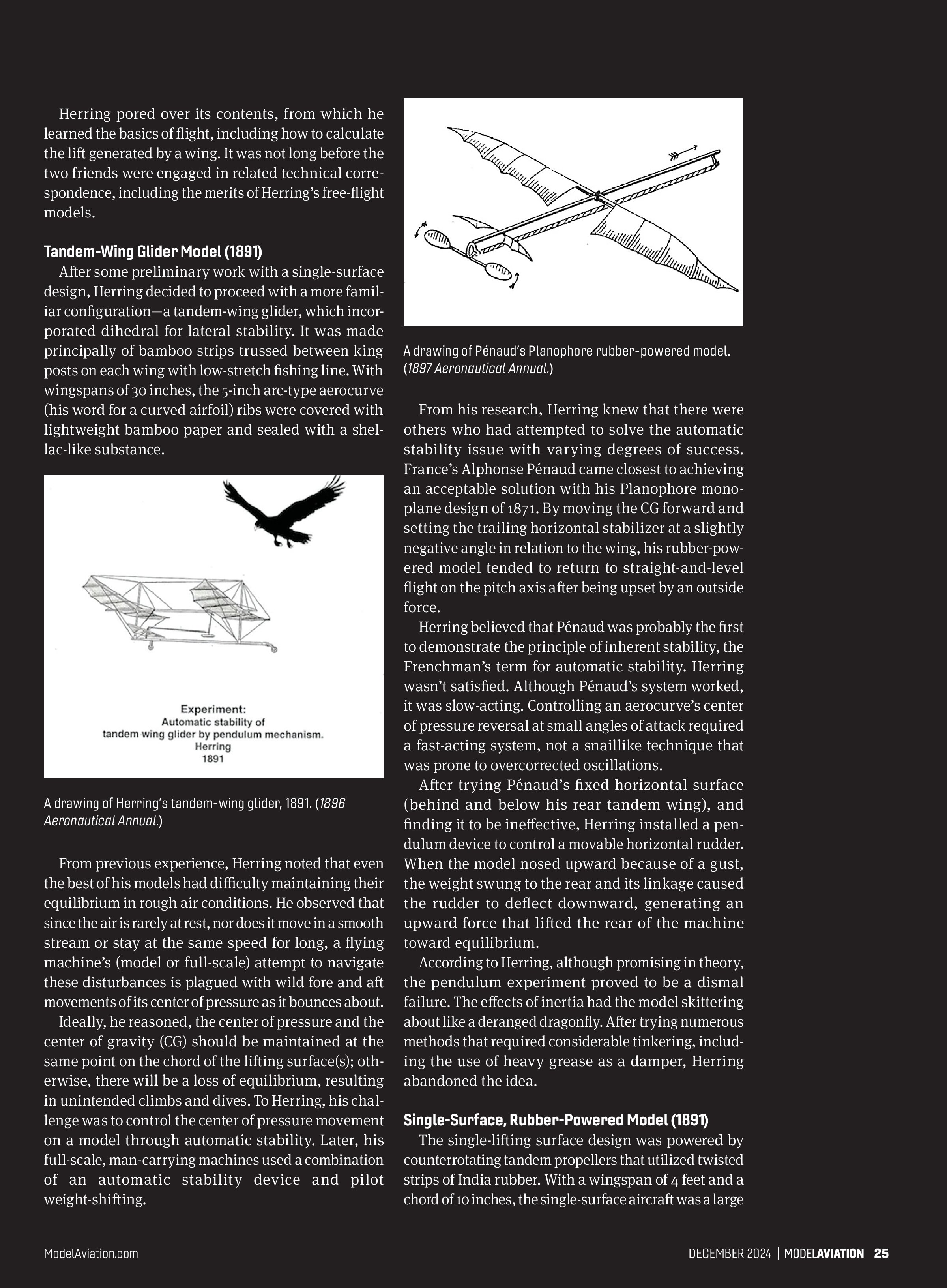
From his research, Herring knew that there were others who had attempted to solve the automatic stability issue with varying degrees of success. France’s Alphonse Pénaud came closest to achieving an acceptable solution with his Planophore monoplane design of 1871. By moving the CG forward and setting the trailing horizontal stabilizer at a slightly negative angle in relation to the wing, his rubber-powered model tended to return to straight-and-level flight on the pitch axis after being upset by an outside force.
Herring believed that Pénaud was probably the first to demonstrate the principle of inherent stability, the Frenchman’s term for automatic stability. Herring wasn’t satisfied. Although Pénaud’s system worked, it was slow-acting. Controlling an aerocurve’s center of pressure reversal at small angles of attack required a fast-acting system, not a snail-like technique that was prone to overcorrected oscillations.
After trying Pénaud’s fixed horizontal surface (behind and below his rear tandem wing), and finding it to be ineffective, Herring installed a pendulum device to control a movable horizontal rudder. When the model nosed upward because of a gust, the weight swung to the rear and its linkage caused the rudder to deflect downward, generating an upward force that lifted the rear of the machine toward equilibrium.
According to Herring, although promising in theory, the pendulum experiment proved to be a dismal failure. The effects of inertia had the model skittering about like a deranged dragonfly. After trying numerous methods that required considerable tinkering, including the use of heavy grease as a damper, Herring abandoned the idea.
Single-Surface, Rubber-Powered Model (1891)
The single-lifting surface design was powered by counterrotating tandem propellers that utilized twisted strips of India rubber. With a wingspan of 4 feet and a chord of 10 inches, the single-surface aircraft was a large

A drawing of Herring’s tandem-wing glider, 1891. (1896 Aeronautical Annual.)
A drawing of Pénaud’s Planophore rubber-powered model. (1897 Aeronautical Annual.)

Two-Surface, Rubber-Powered Model (1892)
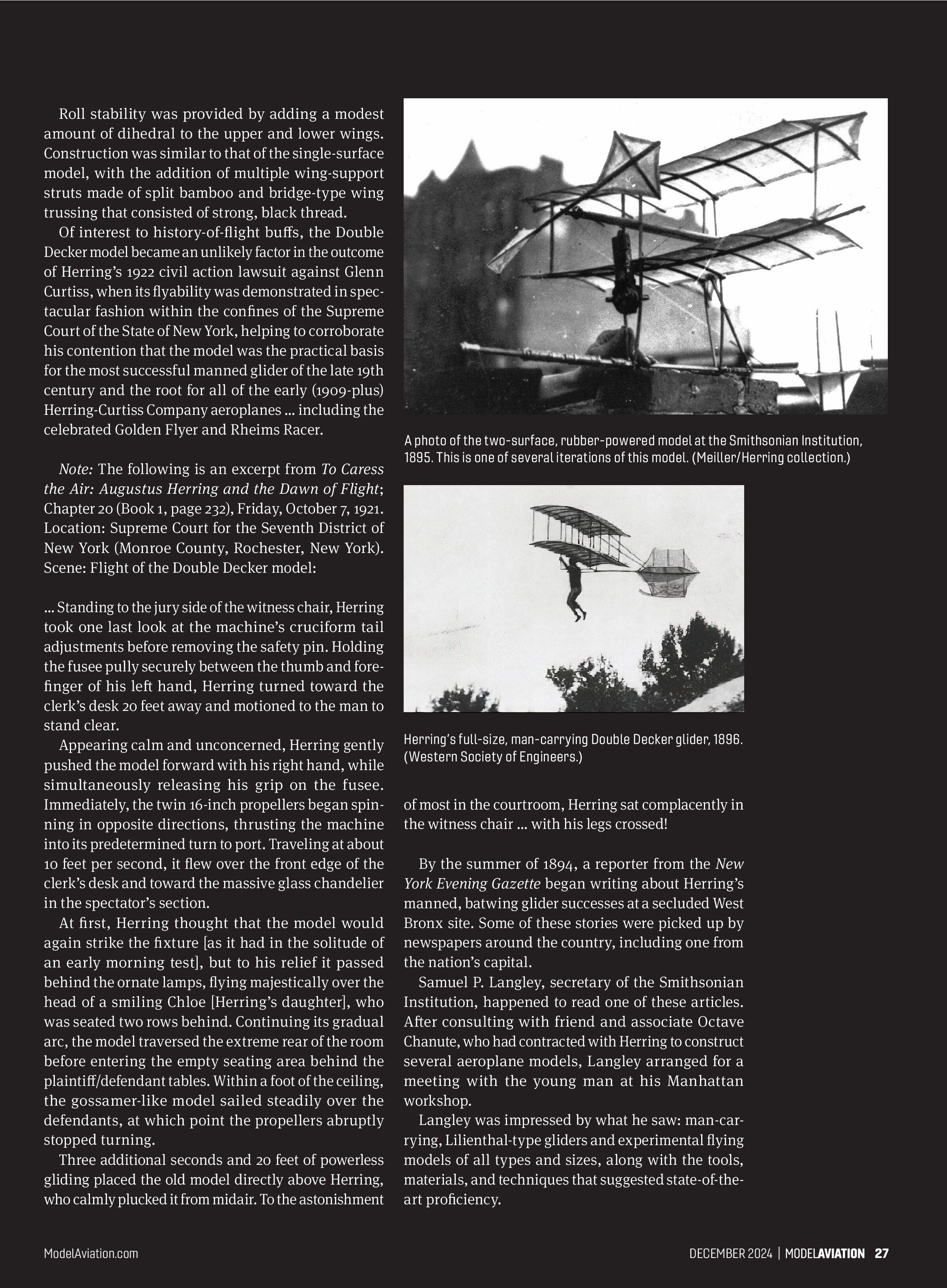
model. Having the distinction of being the first propeller-driven model to incorporate an aerocurve, the machine was also fitted with a Caley-type cruciform tail (empennage). Its vertical and horizontal surfaces worked well with Herring’s idea for automatic stability.
The arrangement of the machine’s components represented a pattern that Herring would use on his models and full-scale designs throughout the 1890s. The lifting surface(s) and the propeller’s axis were located high on the machine’s frame, while the cruciform tail was placed below.
New to the single-surface design was the Herring regulator, his latest automatic stability brainstorm that was claimed to subdue the chaos generated by disruptive gusts. According to the inventor, disturbances in the wind—diminutive whirlpools that travel horizontally, vertically, and diagonally—affect the stability of all things that venture into the air.
His regulator provided a gimbal-like action to the cruciform tail that allowed its vertical and horizontal rudders to move freely about its pivot on the fuselage stick. The surfaces were connected by strong, black thread and were restrained by rubber springs to an anchor point on the forward frame. When carefully adjusted, the regulator allowed the model to pass smoothly through disruptive air, whereas the same machine without the device installed was conclusively unmanageable.
An interesting anecdote concerning the single-surface model: Although Herring thoroughly described and illustrated the model that appeared in his 1896 Aeronautical Annual magazine article, the cruciform tail and regulator portion of the drawing proved to be puzzling!

The single-surface, rubber-powered model incorporated similar building materials and techniques as used with the tandem-wing model; it flew for up to 10 seconds and distances of 135 feet. Although this machine was an improvement over the tandem wing, it didn’t fly well until its CG and propeller thrustline had been carefully optimized. The regulating mechanism then began to show promise.
Two-Surface, Rubber-Powered Model (1892)
Herring’s two-surface, rubber-powered design of 1892, often referred to as his Double Decker model, was definitively a great performer. Its layout represented the origin for all of his man-carrying machines—both gliders and powered.
With a wingspan of only 24 inches and a total area of 288 sq. in., the model incorporated two 16-inch diameter counterrotating propellers—one tractor and one pusher. Both operated from the same twisted India rubber motor. Similar in appearance to his earlier single-surface design, the Double Decker included an upgraded version of his regulator, which provided a degree of automatic stability on the pitch and yaw axis.
According to Herring, “The cruciform tail is hinged so that it turns freely about its pitch and yaw axis. The tail is restrained in the neutral position by elastic cords. When deflected by the force of a wayward gust, the tail stretches out any momentary disturbance over a longer period of time, and thereby prevents (through the action of springs) any sudden tilting of the machine when the angle of the tail path changes from a plus to a minus angle.”

Roll stability was provided by adding a modest amount of dihedral to the upper and lower wings. Construction was similar to that of the single-surface model, with the addition of multiple wing-support struts made of split bamboo and bridge-type wing trussing that consisted of strong, black thread.
Of interest to history-of-flight buffs, the Double Decker model became an unlikely factor in the outcome of Herring’s 1922 civil action lawsuit against Glenn Curtiss, when its flyability was demonstrated in spectacular fashion within the confines of the Supreme Court of the State of New York, helping to corroborate his contention that the model was the practical basis for the most successful manned glider of the late 19th century and the root for all of the early (1909-plus) Herring-Curtiss Company aeroplanes ... including the celebrated Golden Flyer and Rheims Racer.
Note: The following is an excerpt from To Caress the Air: Augustus Herring and the Dawn of Flight; Chapter 20 (Book 1, page 232), Friday, October 7, 1921. Location: Supreme Court for the Seventh District of New York (Monroe County, Rochester, New York). Scene: Flight of the Double Decker model:
... Standing to the jury side of the witness chair, Herring took one last look at the machine’s cruciform tail adjustments before removing the safety pin. Holding the fusee pully securely between the thumb and forefinger of his left hand, Herring turned toward the clerk’s desk 20 feet away and motioned to the man to stand clear.
Appearing calm and unconcerned, Herring gently pushed the model forward with his right hand, while simultaneously releasing his grip on the fusee. Immediately, the twin 16-inch propellers began spinning in opposite directions, thrusting the machine into its predetermined turn to port. Traveling at about 10 feet per second, it flew over the front edge of the clerk’s desk and toward the massive glass chandelier in the spectator’s section.
At first, Herring thought that the model would again strike the fixture [as it had in the solitude of an early morning test], but to his relief it passed behind the ornate lamps, flying majestically over the head of a smiling Chloe [Herring’s daughter], who was seated two rows behind. Continuing its gradual arc, the model traversed the extreme rear of the room before entering the empty seating area behind the plaintiff/defendant tables. Within a foot of the ceiling, the gossamer-like model sailed steadily over the defendants, at which point the propellers abruptly stopped turning.
Three additional seconds and 20 feet of powerless gliding placed the old model directly above Herring, who calmly plucked it from midair. To the astonishment


of most in the courtroom, Herring sat complacently in the witness chair ... with his legs crossed!
By the summer of 1894, a reporter from the New York Evening Gazette began writing about Herring’s manned, batwing glider successes at a secluded West Bronx site. Some of these stories were picked up by newspapers around the country, including one from the nation’s capital.
Samuel P. Langley, secretary of the Smithsonian Institution, happened to read one of these articles. After consulting with friend and associate Octave Chanute, who had contracted with Herring to construct several aeroplane models, Langley arranged for a meeting with the young man at his Manhattan workshop.
Langley was impressed by what he saw: man-carrying, Lilienthal-type gliders and experimental flying models of all types and sizes, along with the tools, materials, and techniques that suggested state-of-the-art proficiency.
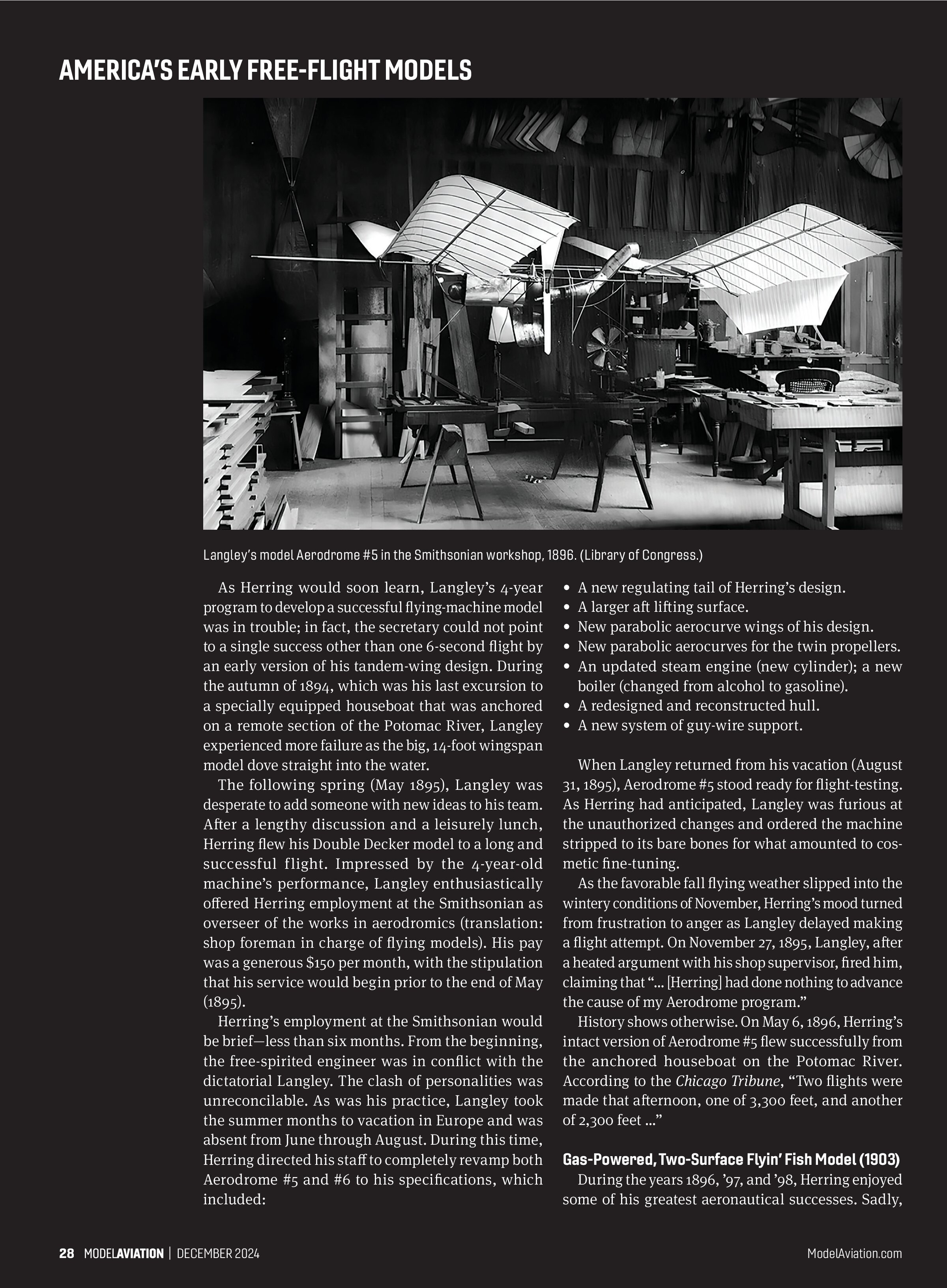
As Herring would soon learn, Langley’s 4-year program to develop a successful flying-machine model was in trouble; in fact, the secretary could not point to a single success other than one 6-second flight by an early version of his tandem-wing design. During the autumn of 1894, which was his last excursion to a specially equipped houseboat that was anchored on a remote section of the Potomac River, Langley experienced more failure as the big, 14-foot wingspan model dove straight into the water.
The following spring (May 1895), Langley was desperate to add someone with new ideas to his team. After a lengthy discussion and a leisurely lunch, Herring flew his Double Decker model to a long and successful flight. Impressed by the 4-year-old machine’s performance, Langley enthusiastically offered Herring employment at the Smithsonian as overseer of the works in aerodromics (translation: shop foreman in charge of flying models). His pay was a generous $150 per month, with the stipulation that his service would begin prior to the end of May (1895).
Herring’s employment at the Smithsonian would be brief—less than six months. From the beginning, the free-spirited engineer was in conflict with the dictatorial Langley. The clash of personalities was irreconcilable. As was his practice, Langley took the summer months to vacation in Europe and was absent from June through August. During this time, Herring directed his staff to completely revamp both Aerodrome #5 and #6 to his specifications, which included:
- A new regulating tail of Herring’s design.
- A larger aft lifting surface.
- New parabolic aerocurve wings of his design.
- New parabolic aerocurves for the twin propellers.
- An updated steam engine (new cylinder); a new boiler (changed from alcohol to gasoline).
- A redesigned and reconstructed hull.
- A new system of guy-wire support.
When Langley returned from his vacation (August 31, 1895), Aerodrome #5 stood ready for flight-testing. As Herring had anticipated, Langley was furious at the unauthorized changes and ordered the machine stripped to its bare bones for what amounted to cosmetic fine-tuning.
As the favorable fall flying weather slipped into the wintery conditions of November, Herring’s mood turned from frustration to anger as Langley delayed making a flight attempt. On November 27, 1895, Langley, after a heated argument with his shop supervisor, fired him, claiming that “ [Herring] had done nothing to advance the cause of my Aerodrome program.”
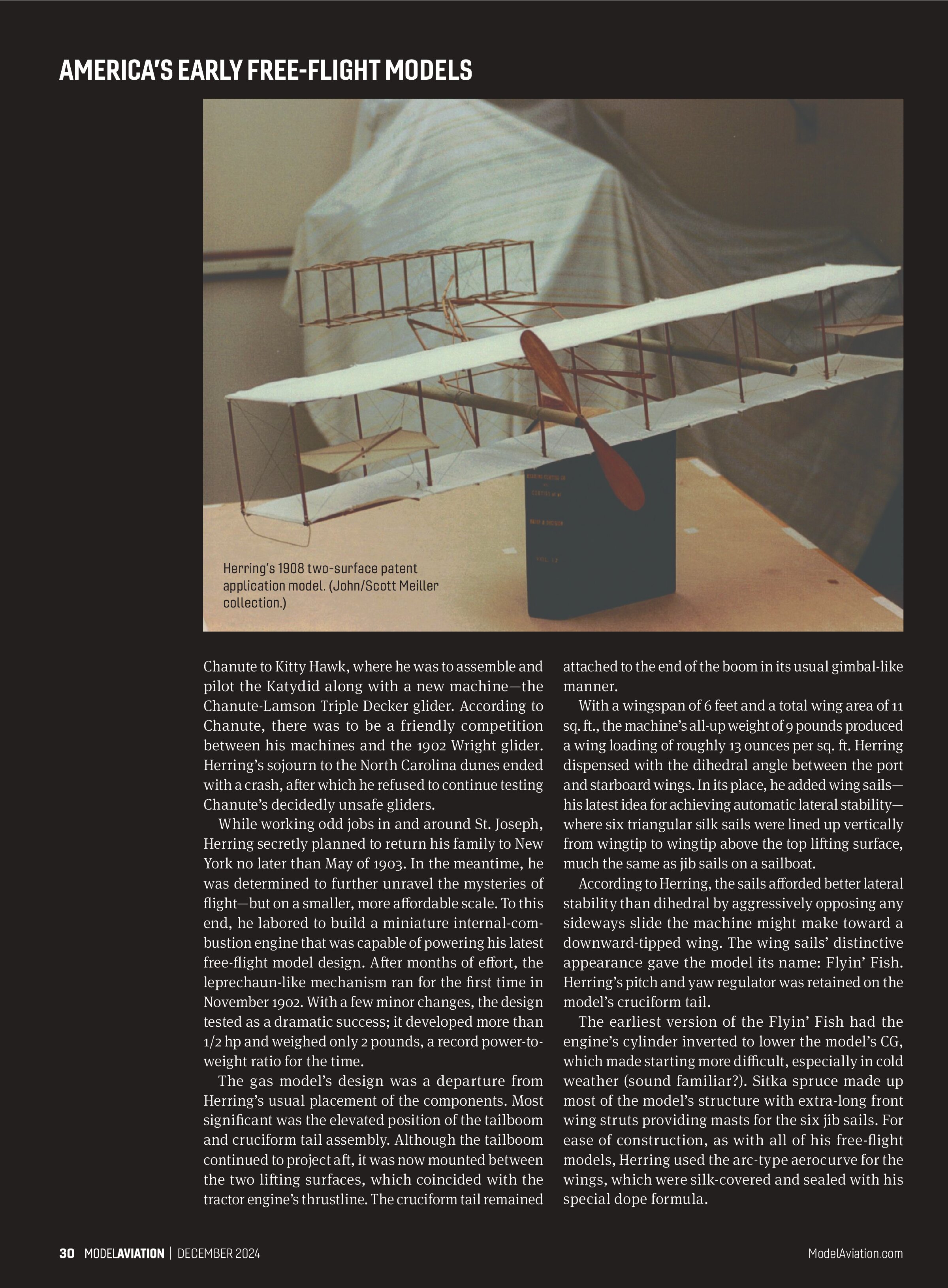
History shows otherwise. On May 6, 1896, Herring’s intact version of Aerodrome #5 flew successfully from the anchored houseboat on the Potomac River. According to the Chicago Tribune, “Two flights were made that afternoon, one of 3,300 feet, and another of 2,300 feet ...”
Gas-Powered, Two-Surface Flyin’ Fish Model (1903)
During the years 1896, ’97, and ’98, Herring enjoyed some of his greatest aeronautical successes. Sadly, his run of innovation and creativity was severely curtailed when his workshop and all of its contents were destroyed in a fire (St. Joseph, Michigan, September 10, 1899).
Because of an unfounded opinion and ignorance on the part of his employer, Herring was fired from his engineering position early in 1900. The following year, while fighting personal bankruptcy, Herring’s partner and benefactor, Mathias Arnot, died unexpectedly. Depressed and barely able to provide for his family, Herring’s prospects finally began to improve in the spring of 1902.
Octave Chanute, his former employer, offered him a modest contract to refurbish and improve the old man’s 6-year-old Katydid glider. Accomplishing his mission, Herring was then hired to accompany


Chanute to Kitty Hawk, where he was to assemble and pilot the Katydid along with a new machine—the Chanute-Lamson Triple Decker glider. According to Chanute, there was to be a friendly competition between his machines and the 1902 Wright glider. Herring’s sojourn to the North Carolina dunes ended with a crash, after which he refused to continue testing Chanute’s decidedly unsafe gliders.
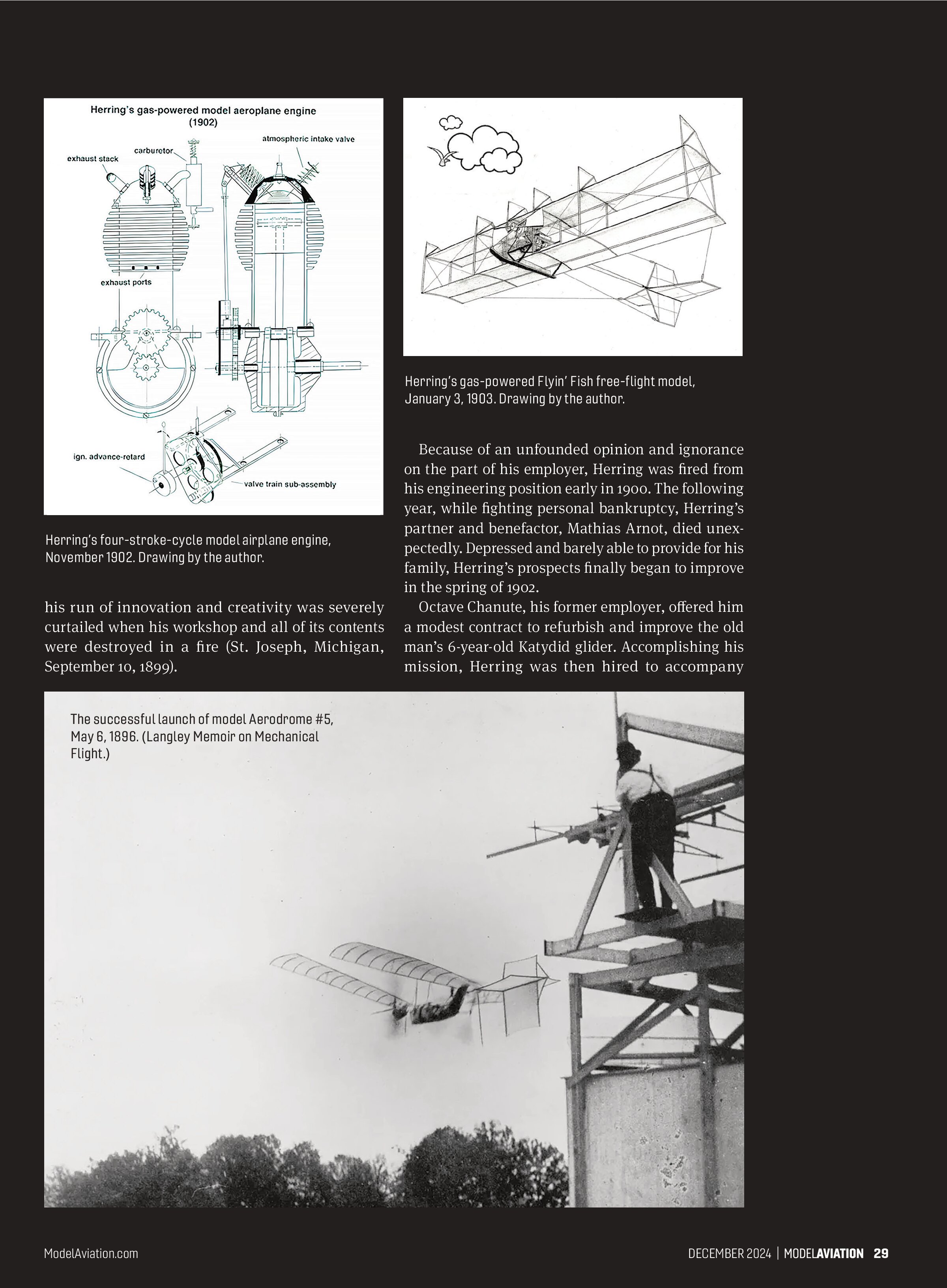
While working odd jobs in and around St. Joseph, Herring secretly planned to return his family to New York no later than May of 1903. In the meantime, he was determined to further unravel the mysteries of flight—but on a smaller, more affordable scale. To this end, he labored to build a miniature internal-combustion engine that was capable of powering his latest free-flight model design. After months of effort, the leprechaun-like mechanism ran for the first time in November 1902. With a few minor changes, the design tested as a dramatic success; it developed more than 1/2 hp and weighed only 2 pounds, a record power-to-weight ratio for the time.
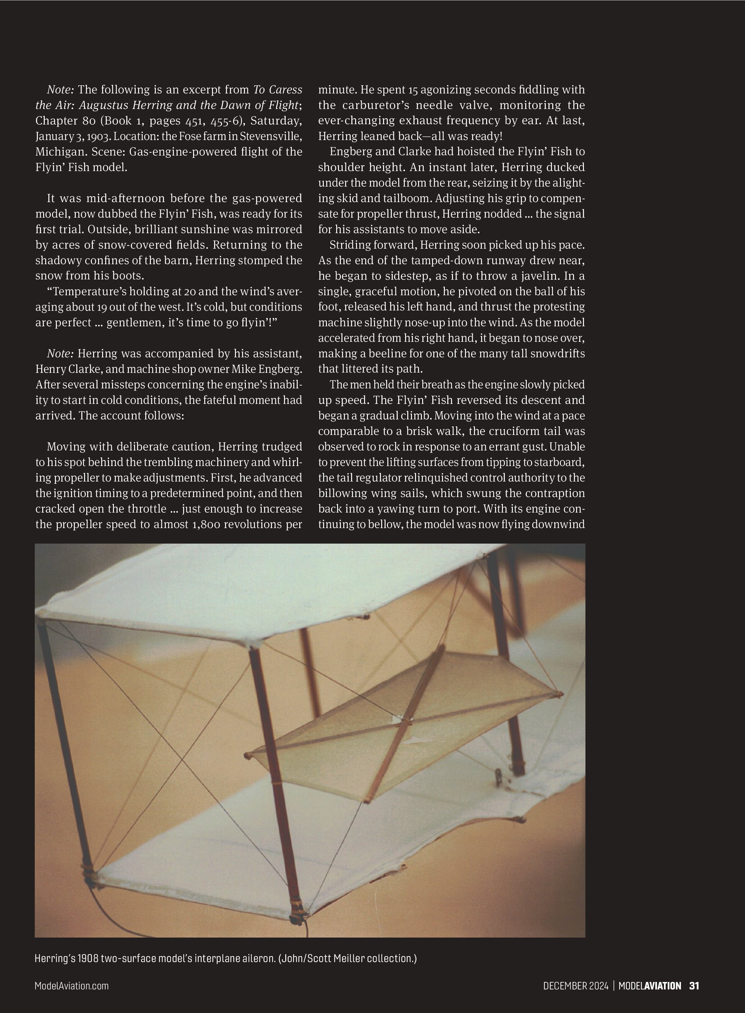
The gas model’s design was a departure from Herring’s usual placement of the components. Most significant was the elevated position of the tailboom and cruciform tail assembly. Although the tailboom continued to project aft, it was now mounted between the two lifting surfaces, which coincided with the tractor engine’s thrustline. The cruciform tail remained attached to the end of the boom in its usual gimbal-like manner.
With a wingspan of 6 feet and a total wing area of 11 sq. ft., the machine’s all-up weight of 9 pounds produced a wing loading of roughly 13 ounces per sq. ft. Herring dispensed with the dihedral angle between the port and starboard wings. In its place, he added wing sails—his latest idea for achieving automatic lateral stability—where six triangular silk sails were lined up vertically from wingtip to wingtip above the top lifting surface, much the same as jib sails on a sailboat.
According to Herring, the sails afforded better lateral stability than dihedral by aggressively opposing any sideways slide the machine might make toward a downward-tipped wing. The wing sails’ distinctive appearance gave the model its name: Flyin’ Fish. Herring’s pitch and yaw regulator was retained on the model’s cruciform tail.
The earliest version of the Flyin’ Fish had the engine’s cylinder inverted to lower the model’s CG, which made starting more difficult, especially in cold weather (sound familiar?). Sitka spruce made up most of the model’s structure with extra-long front wing struts providing masts for the six jib sails. For ease of construction, as with all of his free-flight models, Herring used the arc-type aerocurve for the wings, which were silk-covered and sealed with his special dope formula.
Note: The following is an excerpt from To Caress the Air: Augustus Herring and the Dawn of Flight; Chapter 80 (Book 1, pages 451, 455-6), Saturday, January 3, 1903. Location: the Fose farm in Stevensville, Michigan. Scene: Gas-engine-powered flight of the Flyin’ Fish model.
It was mid-afternoon before the gas-powered model, now dubbed the Flyin’ Fish, was ready for its first trial. Outside, brilliant sunshine was mirrored by acres of snow-covered fields. Returning to the shadowy confines of the barn, Herring stomped the snow from his boots.
“Temperature’s holding at 20 and the wind’s averaging about 19 out of the west. It’s cold, but conditions are perfect ... gentlemen, it’s time to go flyin’!”
Note: Herring was accompanied by his assistant, Henry Clarke, and machine shop owner Mike Engberg. After several missteps concerning the engine’s inability to start in cold conditions, the fateful moment had arrived. The account follows:
Moving with deliberate caution, Herring trudged to his spot behind the trembling machinery and whirling propeller to make adjustments. First, he advanced the ignition timing to a predetermined point, and then cracked open the throttle ... just enough to increase the propeller speed to almost 1,800 revolutions per minute. He spent 15 agonizing seconds fiddling with the carburetor’s needle valve, monitoring the ever-changing exhaust frequency by ear. At last, Herring leaned back—all was ready!
Engberg and Clarke had hoisted the Flyin’ Fish to shoulder height. An instant later, Herring ducked under the model from the rear, seizing it by the alighting skid and tailboom. Adjusting his grip to compensate for propeller thrust, Herring nodded ... the signal for his assistants to move aside.
Striding forward, Herring soon picked up his pace. As the end of the tamped-down runway drew near, he began to sidestep, as if to throw a javelin. In a single, graceful motion, he pivoted on the ball of his foot, released his left hand, and thrust the protesting machine slightly nose-up into the wind. As the model accelerated from his right hand, it began to nose over, making a beeline for one of the many tall snowdrifts that littered its path.
The men held their breath as the engine slowly picked up speed. The Flyin’ Fish reversed its descent and began a gradual climb. Moving into the wind at a pace comparable to a brisk walk, the cruciform tail was observed to rock in response to an errant gust. Unable to prevent the lifting surfaces from tipping to starboard, the tail regulator relinquished control authority to the billowing wing sails, which swung the contraption back into a yawing turn to port. With its engine continuing to bellow, the model was now flying downwind

with increased ground speed. A dozen seconds later and 100 feet above the snow-swept field, it began to soar in wide, hawk-like circles ...
At about four-and-a-half minutes into the flight, it began to snow. The white model became difficult to see as it blended into the gray sky and snow-dominated landscape. Suddenly, the sky went silent as the engine apparently ran out of fuel. Five hundred feet to the east of where the men stood, the Flyin’ Fish continued to glide, making leisurely circles into the wintery abyss. The moment Clarke thought he saw the model touch down, he clicked off the stopwatch. It read six minutes and 22 seconds.
Two-Surface Patent Application Model of 1908
Herring’s rubber-powered two-surface model of 1908 resembled his full-scale U.S. Army Signal Corps machine; they were built concurrently. When completed, the working model was tested and shipped to the patent office, along with his application for A Gyroscopic-Precession Control System for the Automatic Stabilization of an Aeroplane. If granted, Herring’s patent had a chance to defeat the Wrights’ patent for lateral control.
Gyroscopic Precession
By harnessing the actions of two adjacent, opposite-rotating propellers, Herring devised a mechanical system to achieve automatic stability on the aeroplane’s pitch axis. The same results could be realized on the lateral axis by using direct-current electric motors that spun rotor-type gyroscopes—in this case, one for each interplane aileron. By limiting the pilot’s
control inputs to an occasional interruption of the gyroscopically directed flight path, the system would effectively bypass the Wrights’ patent claim that “the machine [was] intended to be generally used with an operator.”
The rubber-powered, twin, counterrotating, pusher-type propellers were mounted toward the trailing edge of a 30-inch wingspan model. A gimbaled, two-surface canard stabilizer/elevator actuated the biplane’s interplane ailerons through a scheme of resilient fishing lines. Constructed of Sitka spruce, bamboo, bamboo paper, and Ambroid cement, the model flew successfully on multiple occasions.
Note: Herring’s Signal Corps government model aeroplane still exists and is the only known artifact to have survived the tumultuous Herring-Curtiss Company years (1909-11). It is currently part of the late John Meiler’s estate. Meiler was Herring’s great, great-grandson.
Epilogue
When the Wrights rejected Herring as a partner in a future flying machine company, the floodgates were opened to a bitter rivalry. The acrimony included technical secrecy on both sides, which caused years of delay in awarding a pioneering patent for a manned, powered, heavier-than-air flying machine. The consequences were costly to both sides of the controversy.
History shows that Herring not only lost out on the patent race but also for recognition of his work with unmanned (models) and powered, auto-stabilized, heavier-than-air flight.
Question for readers: Had there been a Wright-Herring partnership, could Herring’s Flyin’ Fish model have played a role in salvaging America’s infant aeroplane industry?
AMA Discount
Visit Dave Gierke Books for a special discount for AMA members.
SOURCES:
Dave Gierke Books
cdavidgierke@gmail.com
www.davegierkebooks.com