DIRECT CONTROL WITH CUSTOM-PRINTED CONTROL ARMS
By Heath Bartel | heath.bartel@gmail.com

IN A TRADITIONAL SETUP, the servo has a servo arm that is attached to a pushrod. The pushrod then runs back to a control horn that is attached to the control surface. This is a widely used technique because it allows for flexible placement of the servo and easy mechanical adjustments.
When I build wings using this method, I prefer to use a Z-bend on the servo end and a quick connect on the control horn, but what if I could eliminate all of these parts and connect the servo arm directly to the control surface?
A direct-drive control system that connects the servo arm directly to the control surface presents some interesting geometry challenges. A direct-drive control system only has one pivot point. As a result, the servo arm hub and the hinge line of the surface need to align. This limits the possible locations where the servo can be placed.
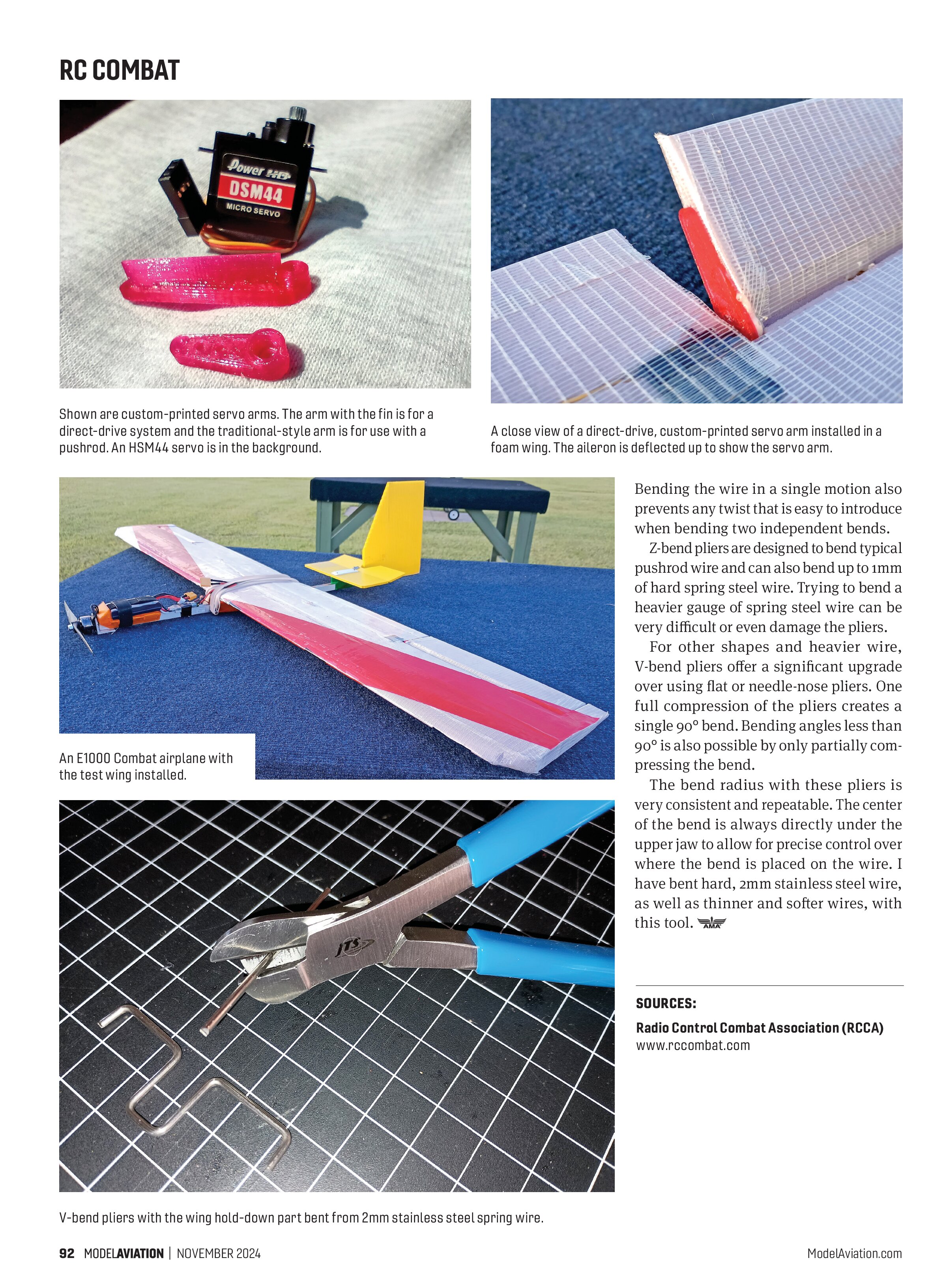
After considering the options, I decided to place the servo at the inside root of the control surface because this placement had the required clearance on both sides of the hinge line and allowed the servo to be completely embedded in the wing. I cut a double bevel on the aileron so that the hinge line would be centered vertically within the wing and aileron. The Power HD DSM44 servo that I am using is very compact. Despite this, it still requires some clearance both in front of and behind the hinge line. To attach the aileron to the wing, I printed some flat thermoplastic polyurethane (TPU) hinges. Matching slits are cut on the aileron and wing and the hinge is glued into the slits.
I have been 3D-printing traditional control horns for these servos, but I needed something a bit different for this direct-drive system. I designed some longer, custom control horns with a fin on the top to provide more contact with the control surface. After cutting a slit into the end of the control surface, the custom servo horn was glued to the end of the surface. After a test fit, I glued everything into place with white Gorilla Glue. I like this glue because it expands and fills any small gaps in the foam to create a very strong bond. I had to remove the excess glue on the hinge line before it hardened. In this case, it might be better to use some foam-safe, thick CA.
With everything securely in place, I connected the servos to my receiver to finish the setup. At this point, I discovered that, while I had pre-centered the servos before installing the control arms, I had installed one of the arms a few degrees off center. As a result, one of the ailerons was slightly deflected. To correct this, I used subtrim on my radio. Because this control system does not have any way to make a physical adjustment, having each servo on a separate channel and a radio that has subtrim are requirements.
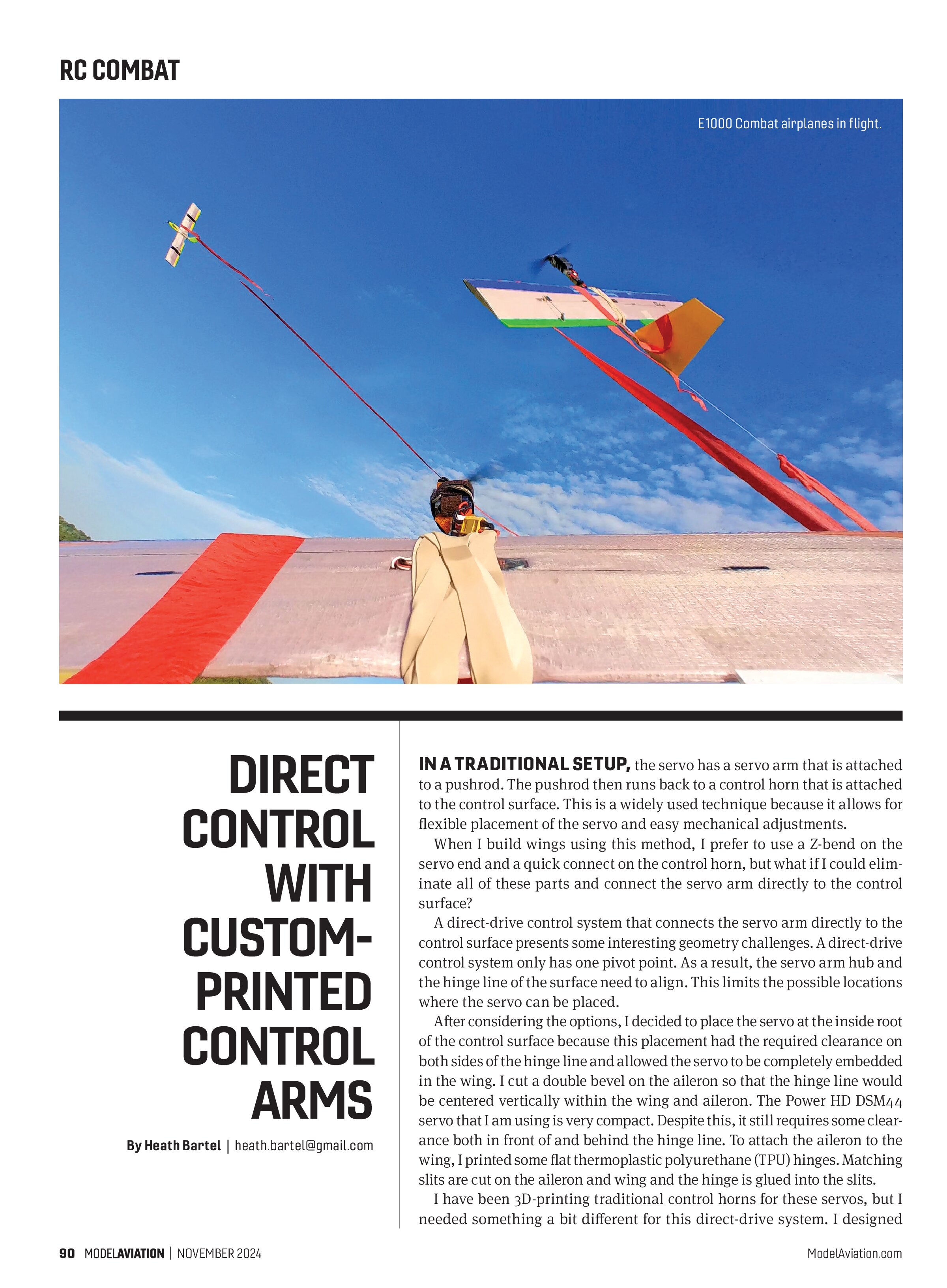
With the wing build complete, I attached it to a proven fuselage. The finished wing looked great, with sleek lines unbroken by any visible control arms or horns, but would they function in flight? There was only one way to find out. I headed to the flying field for a test flight.
My test-flying process is straightforward. I double-checked the center of gravity and made sure that my control surfaces were moving in the correct direction. It was then time to cross my fingers, launch the airplane, uncross my fingers, and, if the airplane was still in the air, trim it out. In this case, the test flight went great. The airplane rolled crisply and required very little trim across a wide range of speeds.
The design appears to be very robust, but I have not yet tested that directly because I have not yet had a big collision that directly impacts the aileron. I am very pleased with this design and have flown it successfully in a number of Combat rounds.
Tool Highlight
Building airplanes is an integral part of flying RC Combat. It is possible to build with only the most basic tools, but some specialized tools make common building tasks much faster, easier, and more fun.
Here are two examples of specialized tools that I find to be very handy and wish I had discovered sooner.
Wire bending can be done with basic flat or needle-nose pliers, but achieving constant, even bends can be difficult. This is where Z-bend pliers and 90° V-bend pliers shine.
Z-bend pliers create two 90° bends in pushrod wire with a single motion. The resulting Z shape will always have the same distance between the corners.


Bending the wire in a single motion also prevents any twist that is easy to introduce when bending two independent bends.
Z-bend pliers are designed to bend typical pushrod wire and can also bend up to 1mm of hard spring steel wire. Trying to bend a heavier gauge of spring steel wire can be very difficult or even damage the pliers.
For other shapes and heavier wire, V-bend pliers offer a significant upgrade over using flat or needle-nose pliers. One full compression of the pliers creates a single 90° bend. Bending angles less than 90° is also possible by only partially compressing the bend.
The bend radius with these pliers is very consistent and repeatable. The center of the bend is always directly under the upper jaw to allow for precise control over where the bend is placed on the wire. I have bent hard, 2mm stainless steel wire, as well as thinner and softer wires, with this tool.
SOURCES:
Radio Control Combat Association (RCCA)
www.rccombat.com