QUICK MOLD
FIBERGLASS
COVER
By Rob Caso | quack916@aol.com
I’VE BEEN WORKING steadily on my 93-inch wingspan carbon-fiber-tube Storch and I needed to replicate the scale sheet-metal cover on the underside of its fuselage, just behind the cowling. I considered making this “one-off” piece out of wood; however, there is little clearance with the two servos that are hiding under the cockpit floor, so I did it in fiberglass, using my “quick mold” method. It’s not a very complex shape, so a simple, single-stage mold that is made using vacuum-formed plastic is perfect for this application.
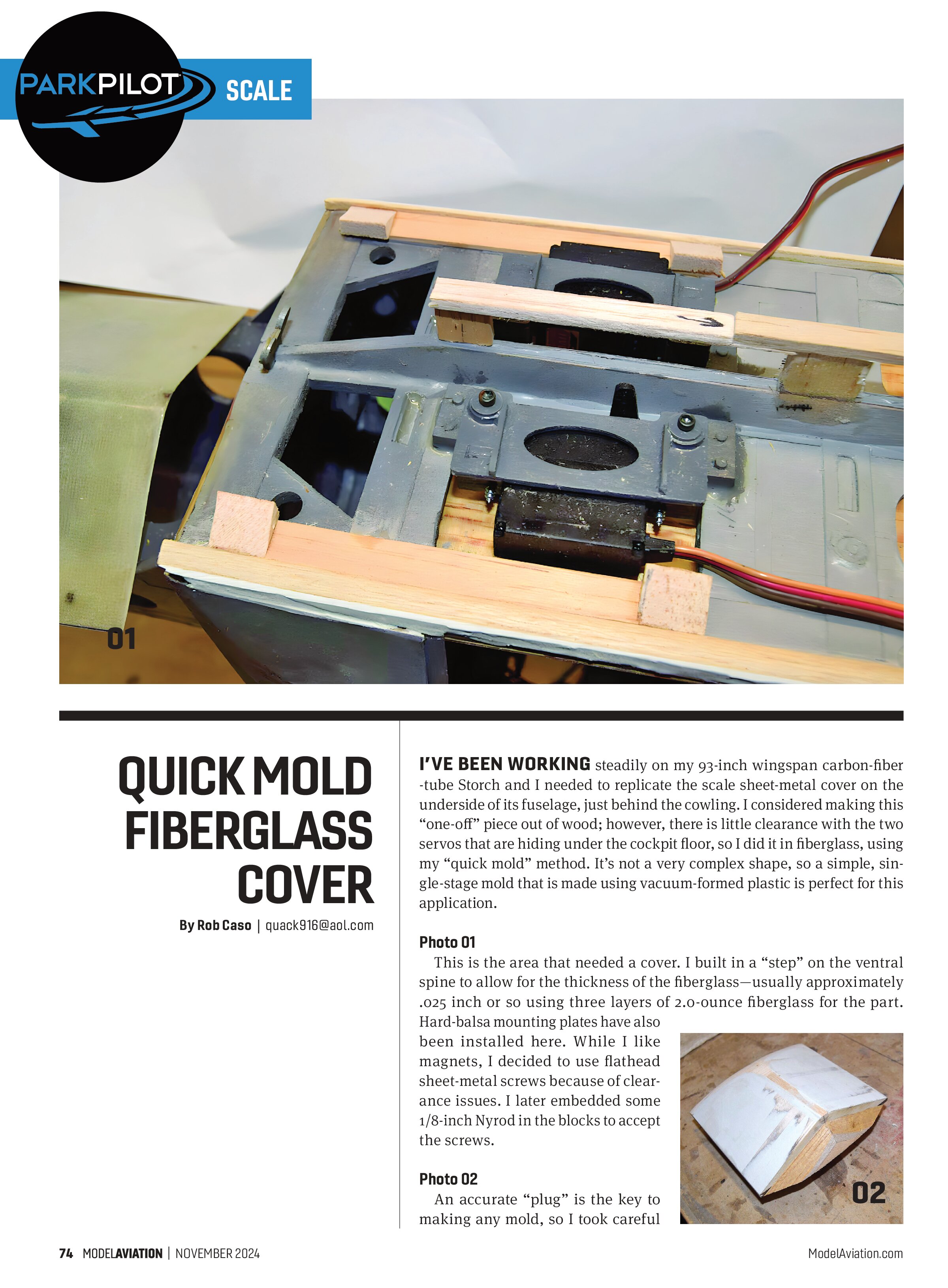
Photo 01
This is the area that needed a cover. I built in a “step” on the ventral spine to allow for the thickness of the fiberglass—usually approximately .025 inch or so using three layers of 2.0-ounce fiberglass for the part. Hard-balsa mounting plates have also been installed here. While I like magnets, I decided to use flathead sheet-metal screws because of clearance issues. I later embedded some 1/8-inch Nyrod in the blocks to accept the screws.


Photo 02 An accurate “plug” is the key to making any mold, so I took careful width and height measurements, making the plug using plywood for the base and profile, filling it with balsa, and finishing it with Evercoat auto body filler. Had this area been open (without the servo mounts and spine), I could have test-fitted the plug directly on the model, but I couldn’t do that here. Therefore, I made the plug slightly oversized to allow for some wiggle room.
Note the “ramp” on the end to give the hot plastic a gradual forming below the sharp corner of the plug. I also installed patches of 1/32-inch hard balsa sheet on the underside of the plug away from its edges to elevate it off of the vacuum table.


Doing so greatly improves the demarcation of the part at its edges.
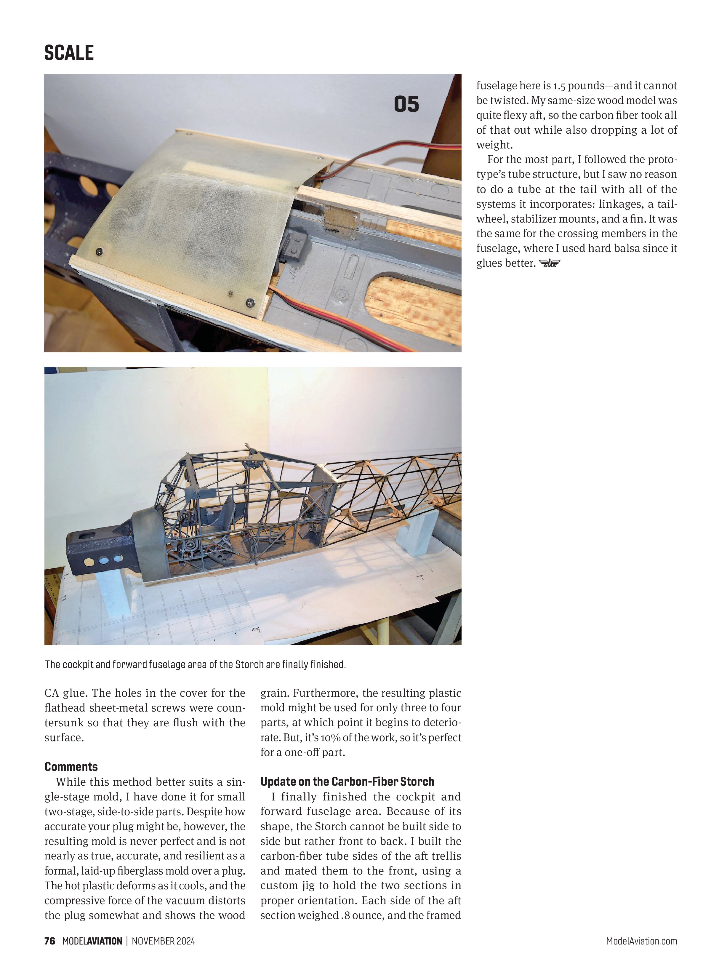
Photo 03 My vacuum table was used to form .030-inch high-impact polystyrene (HIPPS), heated at 350° using an old toaster oven, over the plug. I used to commandeer the good toaster oven in the kitchen for this, but I recommend against doing that!
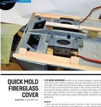
Photo 04 Using West System’s slow-set epoxy, three layers of fiberglass were laid up after waxing what is now a mold, and two coats of polyvinyl alcohol (PVA) mold release were brushed on. I mixed microballoons in with the epoxy to give it some body and to fill the weave of the cloth. I also laid up fiberglass strips at the edges, being careful to come right up to, but not over, the corners, which would cause bubbles. The next morning, I teased the cured part out of the mold with an artist’s spatula.

fuselage here is 1.5 pounds—and it cannot be twisted. My same-size wood model was quite flexy aft, so the carbon fiber took all of that out while also dropping a lot of weight.
For the most part, I followed the prototype’s tube structure, but I saw no reason to do a tube at the tail with all of the systems it incorporates: linkages, a tail-wheel, stabilizer mounts, and a fin. It was the same for the crossing members in the fuselage, where I used hard balsa since it glues better.

CA glue. The holes in the cover for the flathead sheet-metal screws were countersunk so that they are flush with the surface.
Comments
While this method better suits a single-stage mold, I have done it for small two-stage, side-to-side parts. Despite how accurate your plug might be, however, the resulting mold is never perfect and is not nearly as true, accurate, and resilient as a formal, laid-up fiberglass mold over a plug. The hot plastic deforms as it cools, and the compressive force of the vacuum distorts the plug somewhat and shows the wood grain.
Update on the Carbon-Fiber Storch
Furthermore, the resulting plastic mold might be used for only three to four parts, at which point it begins to deteriorate. But, it’s 10% of the work, so it’s perfect for a one-off part.
I finally finished the cockpit and forward fuselage area. Because of its shape, the Storch cannot be built side to side but rather front to back. I built the carbon-fiber tube sides of the aft trellis and mated them to the front, using a custom jig to hold the two sections in proper orientation. Each side of the aft section weighed .8 ounce, and the framed