HOBBY CLUB MUSGER MG19B
Giant Scale sailplanes equal big fun
By Bill Chaterlea | bchaterlea@cox.net
Photos provided by the author

WHEN ALBERTO at Hobby Club sent me some information on a vintage glider kit that he would be importing, I was interested right away. The photos showed a pretty, 1/6-scale, laser-cut kit with some nice scale details. I’ve built several gull-wing vintage gliders during the last few years, mostly from plans, and although they are rewarding to build, they can be time-consuming and require quite a commitment.
What I liked about the kit was that it should be a reasonably quick build because it had mostly laser-cut parts. It’s a fairly unusual subject for a kit. The design looks as though it should have gull wings, but it actually has straight dihedral, again simplifying the build. Best of all is the unusual color. How many Kermit-green vintage gliders have you seen on the flying field?
I decided it was time for some research. After looking through Martin Simons’ excellent Sailplanes 1945-1965 book, I found more information about the original design. Designed by Erwin Musger in Austria as a two-seat tandem trainer and first flown in 1951, the Mg19 and Mg19a versions did indeed have gull wings and proved to be successful in Soaring competitions throughout Europe.
The Mg19b was introduced in 1954 with a straight dihedral wing, retaining the original’s plans shape and section. It was constructed using traditional woodworking techniques. The fuselage was made from oval-sectioned wooden formers and light longerons and skinned with plywood. The wing
At a Glance
Specifications
Wingspan: 115.5 inches
Wing area: 883 sq. in.
Wing loading: 9.7 ounces per sq. ft.
Weight: 3 pounds, 11 ounces
Fuselage length: 53.75 inches
Power system: Dualsky XM3548EGL-9 motor; Castle Creations 50-amp ESC; 3S 1,800 mAh LiPo battery; 12 x 6 folding propeller
Servos: Two Dualsky AS 82 MG and four DS 395
Radio required: Seven-channel transmitter and receiver
Price: $399.95
Pluses
- Kit design.
- Laser-cutting and wood quality.
- Scale details included.
- Lightweight construction leads to a nice-flying model.
Minuses
- Main spar length was slightly short.
- Intricate airbrake construction.
- Instructions slightly lacking in some areas.
Manufacturer/Distributor
Tony Ray Aero Model Co.
www.tonyrayaermodels.co.uk
Hobby Club
(949) 425-1362
www.hobbyclub.com
used a plywood-skinned D-box leading edge (LE) with open construction and fabric covering behind the spar, and Schempp-Hirth-type airbrakes were fitted.
The kit comes in a surprisingly small box for its 115.5-inch wingspan, but it is packed to the top with all manners of sheet and strip wood, a clear two-piece

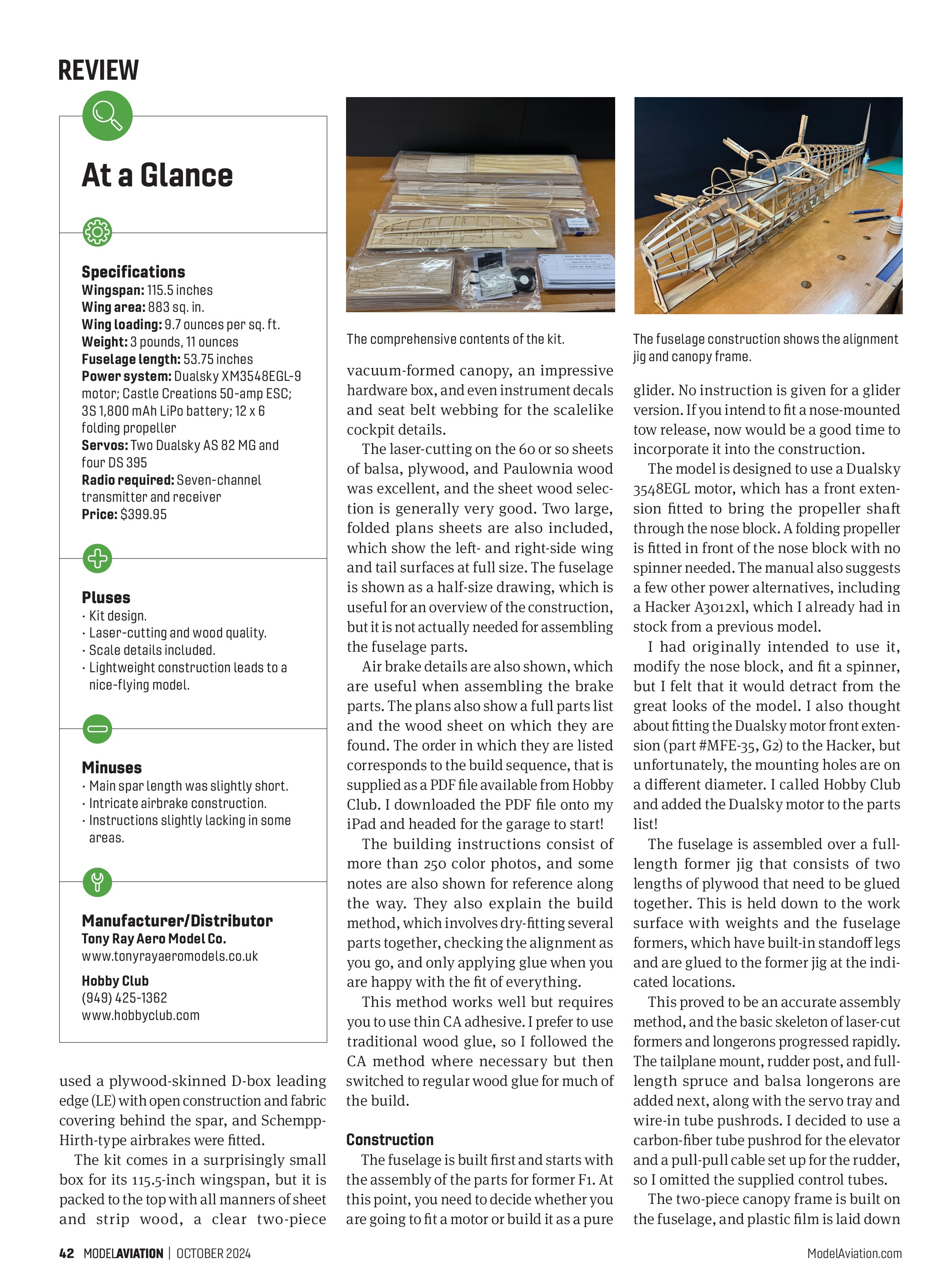
vacuum-formed canopy, an impressive hardware box, and even instrument decals and seat belt webbing for the scalelike cockpit details.
The laser-cutting on the 60 or so sheets of balsa, plywood, and Paulownia wood was excellent, and the sheet wood selection is generally very good. Two large, folded plans sheets are also included, which show the left- and right-side wing and tail surfaces at full size. The fuselage is shown as a half-size drawing, which is useful for an overview of the construction, but it is not actually needed for assembling the fuselage parts.
Air brake details are also shown, which are useful when assembling the brake parts. The plans also show a full parts list and the wood sheet on which they are found. The order in which they are listed corresponds to the build sequence, that is supplied as a PDF file available from Hobby Club. I downloaded the PDF file onto my iPad and headed for the garage to start!
The building instructions consist of more than 250 color photos, and some notes are also shown for reference along the way. They also explain the build method, which involves dry-fitting several parts together, checking the alignment as you go, and only applying glue when you are happy with the fit of everything.
This method works well but requires you to use thin CA adhesive. I prefer to use traditional wood glue, so I followed the CA method where necessary but then switched to regular wood glue for much of the build.
Construction
The fuselage is built first and starts with the assembly of the parts for former F1. At this point, you need to decide whether you are going to fit a motor or build it as a pure

glider. No instruction is given for a glider version. If you intend to fit a nose-mounted tow release, now would be a good time to incorporate it into the construction.
The model is designed to use a Dualsky 3548EGL motor, which has a front extension fitted to bring the propeller shaft through the nose block. A folding propeller is fitted in front of the nose block with no spinner needed. The manual also suggests a few other power alternatives, including a Hacker A3012x1, which I already had in stock from a previous model.
I had originally intended to use it, modify the nose block, and fit a spinner, but I felt that it would detract from the great looks of the model. I also thought about fitting the Dualsky motor front extension (part #MFE-35, G2) to the Hacker, but unfortunately, the mounting holes are on a different diameter. I called Hobby Club and added the Dualsky motor to the parts list!
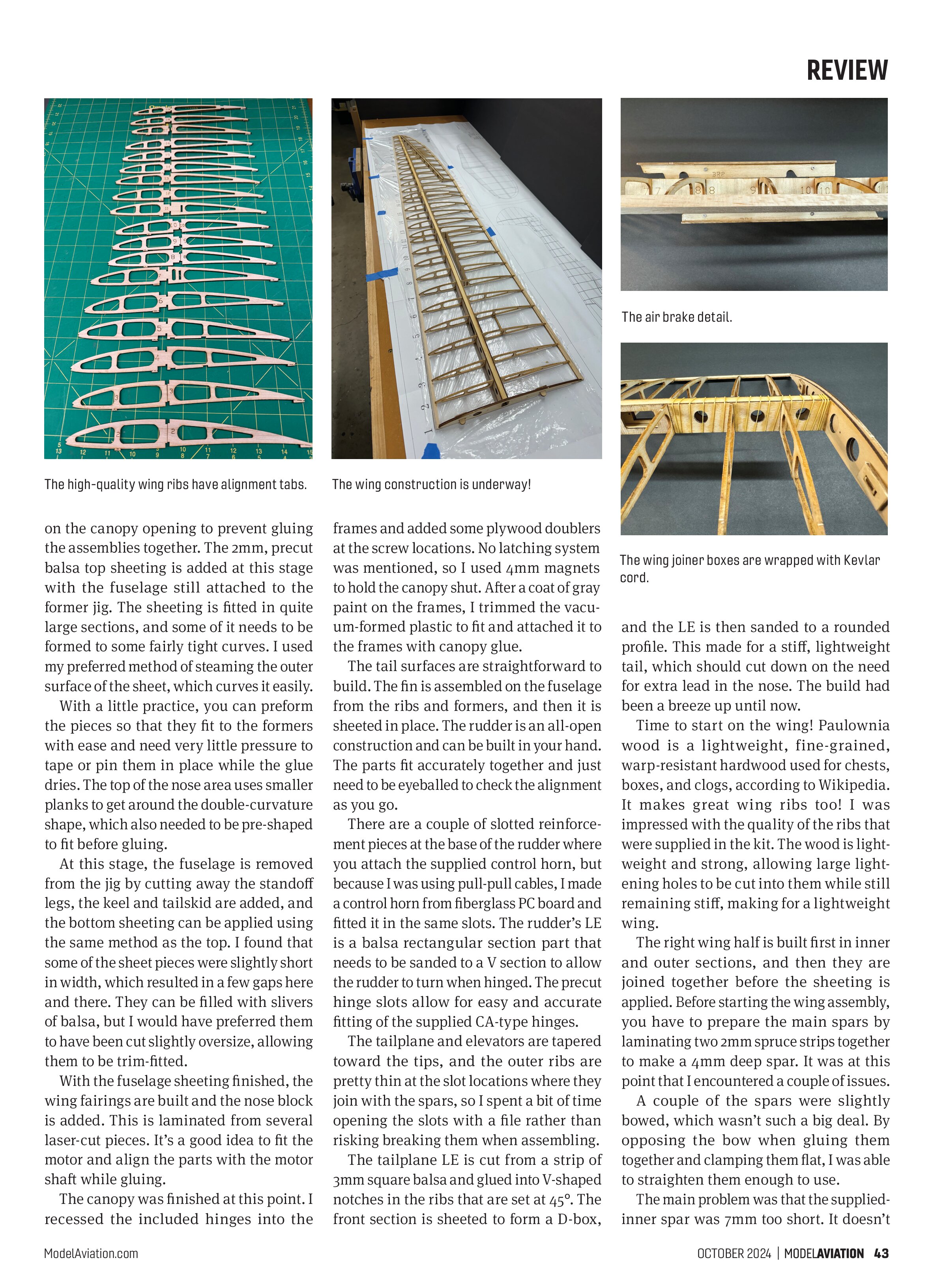
The fuselage is assembled over a full-length former jig that consists of two lengths of plywood that need to be glued together. This is held down to the work surface with weights and the fuselage formers, which have built-in standoff legs and are glued to the former jig at the indicated locations.
This proved to be an accurate assembly method, and the basic skeleton of laser-cut formers and longerons progressed rapidly. The tailplane mount, rudder post, and full-length spruce and balsa longerons are added next, along with the servo tray and wire-in tube pushrods. I decided to use a carbon-fiber tube pushrod for the elevator and a pull-pull cable set up for the rudder, so I omitted the supplied control tubes.
The two-piece canopy frame is built on the fuselage, and plastic film is laid down


on the canopy opening to prevent gluing the assemblies together. The 2mm, precut balsa top sheeting is added at this stage with the fuselage still attached to the former jig. The sheeting is fitted in quite large sections, and some of it needs to be formed to some fairly tight curves. I used my preferred method of steaming the outer surface of the sheet, which curves it easily.
With a little practice, you can preform the pieces so that they fit to the formers with ease and need very little pressure to tape or pin them in place while the glue dries. The top of the nose area uses smaller planks to get around the double-curvature shape, which also needed to be pre-shaped to fit before gluing.
At this stage, the fuselage is removed from the jig by cutting away the standoff legs, the keel and tailskid are added, and the bottom sheeting can be applied using the same method as the top. I found that some of the sheet pieces were slightly short in width, which resulted in a few gaps here and there. They can be filled with slivers of balsa, but I would have preferred them to have been cut slightly oversize, allowing them to be trim-fitted.
With the fuselage sheeting finished, the wing fairings are built and the nose block is added. This is laminated from several laser-cut pieces. It’s a good idea to fit the motor and align the parts with the motor shaft while gluing.
The canopy was finished at this point. I recessed the included hinges into the frames and added some plywood doublers at the screw locations. No latching system was mentioned, so I used 4mm magnets to hold the canopy shut. After a coat of gray paint on the frames, I trimmed the vacuum-formed plastic to fit and attached it to the frames with canopy glue.
The tail surfaces are straightforward to build. The fin is assembled on the fuselage from the ribs and formers, and then it is sheeted in place. The rudder is an all-open construction and can be built in your hand. The parts fit accurately together and just need to be eyeballed to check the alignment as you go.
There are a couple of slotted reinforcement pieces at the base of the rudder where you attach the supplied control horn, but because I was using pull-pull cables, I made a control horn from fiberglass PC board and fitted it in the same slots. The rudder’s LE is a balsa rectangular section part that needs to be sanded to a V section to allow the rudder to turn when hinged. The precut hinge slots allow for easy and accurate fitting of the supplied CA-type hinges.
The tailplane and elevators are tapered toward the tips, and the outer ribs are pretty thin at the slot locations where they join with the spars, so I spent a bit of time opening the slots with a file rather than risking breaking them when assembling. The tailplane LE is cut from a strip of 3mm square balsa and glued into V-shaped notches in the ribs that are set at 45°. The front section is sheeted to form a D-box,
and the LE is then sanded to a rounded profile. This made for a stiff, lightweight tail, which should cut down on the need for extra lead in the nose. The build had been a breeze up until now.
Time to start on the wing! Paulownia wood is a lightweight, fine-grained, warp-resistant hardwood used for chests, boxes, and clogs, according to Wikipedia. It makes great wing ribs too! I was impressed with the quality of the ribs that were supplied in the kit. The wood is lightweight and strong, allowing large lightening holes to be cut into them while still remaining stiff, making for a lightweight wing.
The right wing half is built first in inner and outer sections, and then they are joined together before the sheeting is applied. Before starting the wing assembly, you have to prepare the main spars by laminating two 2mm spruce strips together to make a 4mm deep spar. It was at this point that I encountered a couple of issues.
A couple of the spars were slightly bowed, which wasn’t such a big deal. By opposing the bow when gluing them together and clamping them flat, I was able to straighten them enough to use.
The main problem was that the supplied-inner spar was 7mm too short. It doesn’t
sound like much, and there was enough wood to make the outer spars longer, but it did put the join in an awkward place, leaving not much joining area on the inner spars within the rib bay. I ended up using some of the extra spar material to make a spruce web to fit between the spars, I-beam style, and extending the join into the next rib bay. Then I used the supplied joiner webs according to the instructions. The manufacturer, Tony Ray Aero Model Co., has been told about this issue, so hopefully subsequent kits will have spars of the correct length.
The rest of the wing construction is fairly straightforward and involves assembling the parts over the plans after first covering the plans with plastic film to prevent them from sticking. The lower spars are spaced from the building board by 1.5mm then held down with weights. The wing joiner box sides and the rear spar web are glued to the spars.
Both of the spar webs and trailing edges (TEs) are slotted, so the ribs, which have removeable tabs on the undersides, fit in place at the correct location and attitude. When all of the ribs and air brake box parts are added, the top spar and front spar webs are glued in place.
Outer wing panels are built in the same way. The ailerons, which are integrated into the structure, are cut away later. Wingtip parts, aileron spars, and the servo hatch frame are glued in place; the inner and outer sections are joined together as described earlier; and the LE strips are added.
At this point, it is recommended to build the left wing half because it provides a good point of reference when constructing the air brakes. It pays to study the build manual photos and diagram on the plans before starting to assemble the parts.
The brakes are made from multiple pieces of plywood and Paulownia and marked for each wing half, so having both wing halves in front of you makes it easier to double-check that you’re putting them together correctly. The blades are easily assembled, but the pivoting arms require stacking and gluing multiple small plywood discs to form the spacers/pivots, and they need to be at 90° to the arms for the brakes to operate correctly. If they are off slightly, they will not fit correctly in their housings. Ask me how I know!
This is delicate work, so tweezers, strong glasses, and a steady hand are needed! The arms are an ideal candidate for a molded-plastic or a 3D-printed part. When you have the brakes installed and working correctly, the next task is to reinforce the spar join and wing-joiner boxes by wrapping them with Kevlar cord and epoxy. It’s also advisable to run extension wires for the servos at this point.
The top wing sheeting can now be glued in place. This is all supplied in precut sections along with the rib capstrips, which are also laser-cut to width and just require trimming to length. The underside of the wing is completed in the same manner after first removing the rib alignment tabs. Wingtips are added and sanded to profile along with the wing LES.
The ailerons are now cut away and the facing strips added. These are similar to the rudder that has the hinge slots precut and need to be sanded to a V profile to allow movement.
The final stage is to glue the thin plywood aileron top sheeting in place. This is also beautifully laser-cut with radiused lightening holes that look great with the light coming through them while in flight.
Finishing and Covering
The last few jobs were to glue the wing joiner together, which is made from three precut pieces of 2mm spruce, and to assemble the cockpit details. The seats are made from plywood and balsa and the belts from the supplied webbing material and plywood buckle parts. The instrument panels are made in the same way and are fitted with the supplied decals and screws.
I decided to prefit and test all of the electronics before covering, using 9-gram Dualsky DS 395 servos for the aileron and airbrake, and 17-gram AS 82 MG servos for the elevator and rudder, and a Futaba receiver. A Castle Creations 50-amp ESC was used to power the 820 Kv Dualsky motor. I figured a 4S 1,800 mAh battery would be a good starting point, along with a 14 x 6 folding propeller.
The color scheme, based on a full-scale glider located in Europe, is both striking and unusual, which is what sold me on the kit in the first place! I wanted to keep the model as lightweight as possible, so I used Hangar 9 UltraCote throughout—Lite Translucent White on the open structure and Apple Green on the sheeted areas, with solid white for the trim and letters, which were hand-cut using the graphics shown on the plans.
The completed model tipped the scales at 3 pounds, 11 ounces, including the battery—a respectable weight for an airplane of this size. I set the center of gravity (CG) at 85mm from the wing’s LE, which is the forward point recommended in the instructions, and headed for the flying field!

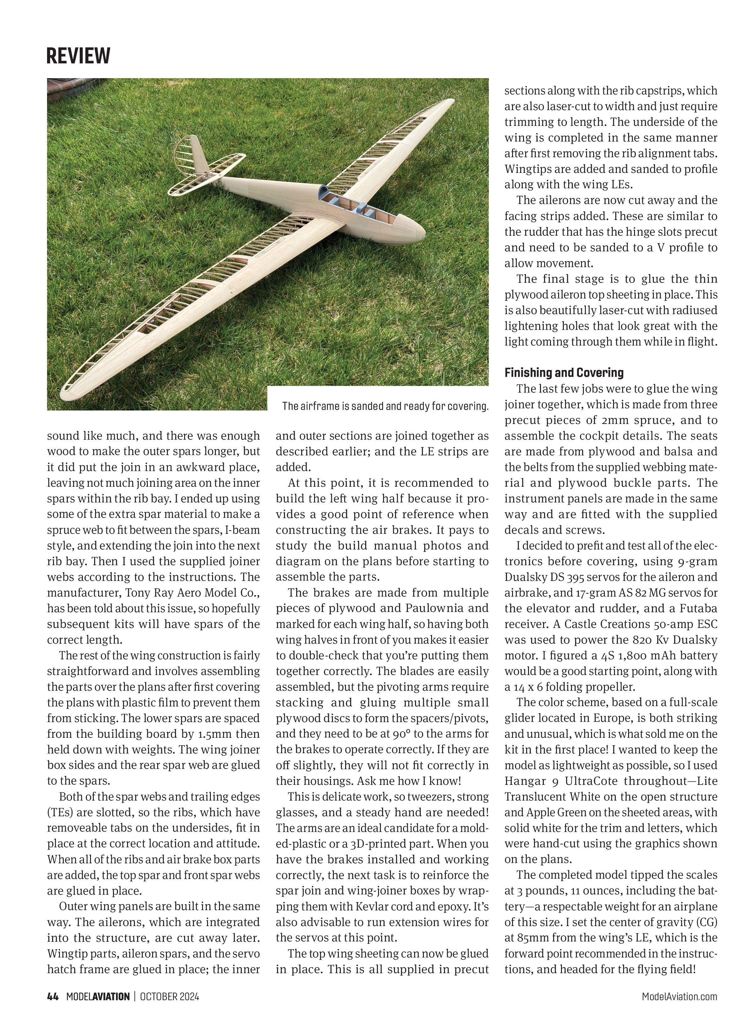
The airframe is sanded and ready for covering.
is on, and moved the CG to the rearward recommended point of 90mm from the LE.
The second outing proved that the power setup was better suited to the model, giving a steady climb to altitude on full power. The weather was breezier, with a wind-speed of at least 10 mph, but the airplane handled it well enough, making headway into the wind and turning nicely with the added aileron movement. The rearward CG was better, although I still had to add a bit of uptrim.
On a calm morning a few days later, I spent several hours finetuning the setup with a local expert, Gary. We added a 2mm shim under the stabilizer’s TE and did several dive tests, moving the CG back incrementally each time. The sweet spot was 98mm from the wing LE, which made the model more responsive. You can practically turn on a wingtip to keep it in a thermal!
Flying

The maiden flight day was partly overcast with a slight breeze, and it looked as though there might be some thermals to catch. There’s always a certain amount of anticipation when flying a new airplane for the first time, especially if you have committed several hours to building it yourself. Having an audience for the first flight adds a little extra pressure. I needn’t have worried. Gene, a fellow glider guider, released the model at half power, and it climbed easily into the sky.
I applied full power and it leapt skyward like a rocket. The power system is more than enough for this model. At a reasonable height, I cut the power and found that it needed a fair amount of uptrim to achieve a nice glide, indicating that the CG was probably slightly too far forward. The turns were good. The ailerons were fairly effective with the recommended 3-to-1 differential added, but it needed some rudder fed in during the turn, as expected for this type of model. I made a couple more climbs to altitude and found some light lift. The model responded well and I was able to do some fairly tight circles with no tendency to tip-stall.
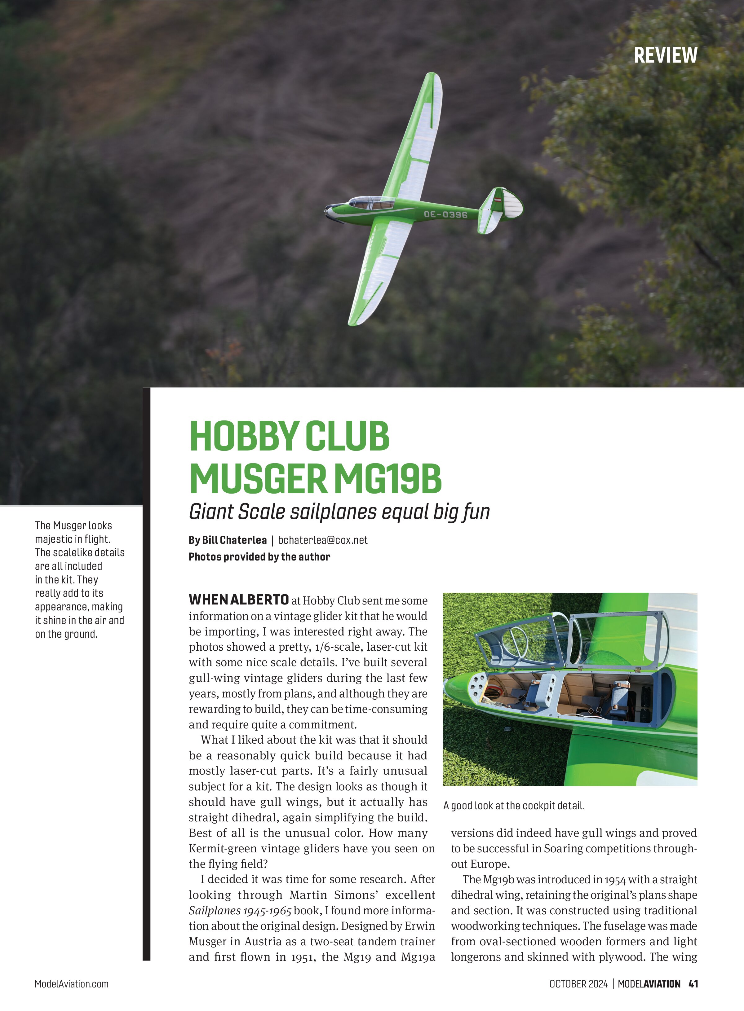
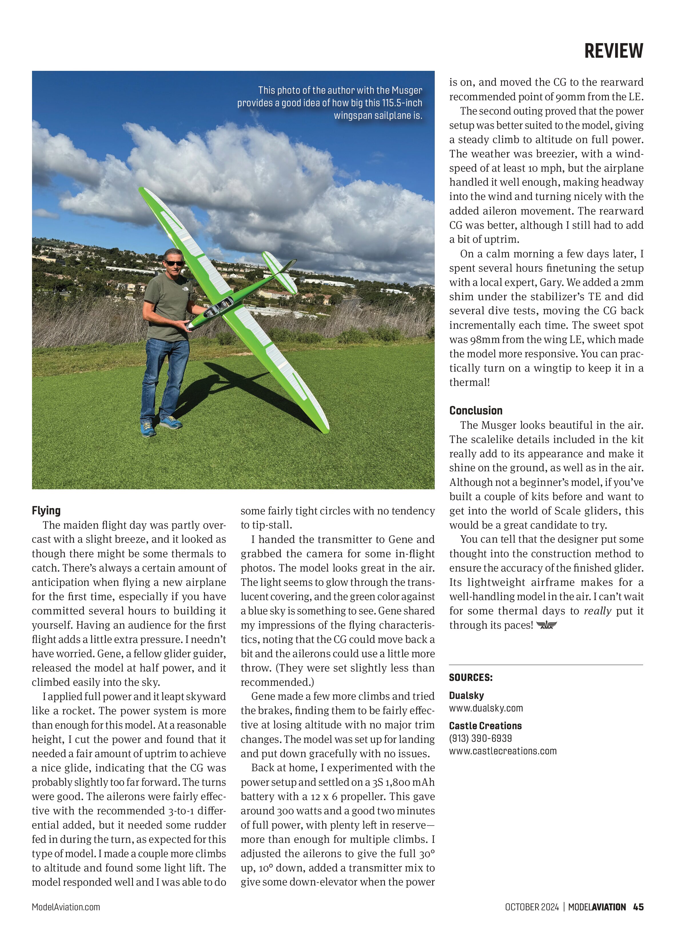
I handed the transmitter to Gene and grabbed the camera for some in-flight photos. The model looks great in the air. The light seems to glow through the translucent covering, and the green color against a blue sky is something to see. Gene shared my impressions of the flying characteristics, noting that the CG could move back a bit and the ailerons could use a little more throw. (They were set slightly less than recommended.)
Gene made a few more climbs and tried the brakes, finding them to be fairly effective at losing altitude with no major trim changes. The model was set up for landing and put down gracefully with no issues.
Back at home, I experimented with the power setup and settled on a 3S 1,800mAh battery with a 12 x 6 propeller. This gave around 300 watts and a good two minutes of full power, with plenty left in reserve—more than enough for multiple climbs. I adjusted the ailerons to give the full 30° up, 10° down, added a transmitter mix to give some down-elevator when the power
Conclusion
The Musger looks beautiful in the air. The scalelike details included in the kit really add to its appearance and make it shine on the ground, as well as in the air. Although not a beginner’s model, if you’ve built a couple of kits before and want to get into the world of Scale gliders, this would be a great candidate to try.
You can tell that the designer put some thought into the construction method to ensure the accuracy of the finished glider. Its lightweight airframe makes for a well-handling model in the air. I can’t wait for some thermal days to really put it through its paces!
SOURCES:
Dualsky
www.dualsky.com
Castle Creations
(913) 390-6939
www.castlecreations.com