Schneider Grunau Baby Scale Sailplane
Reduced vibration means lower airframe fatigue
By Stan Alexander | onawing4602@att.net
Photos by the author

HOBBY CLUB is an online source for a multitude of hobby products. These products include traditional balsa/plywood models, ARFs, and RTF models. The company has several scale kits, including this Grunau Baby Sailplane, powered models such as the Miles Hawk, and indoor or schoolyard-size models as well. It has links to most major electronics suppliers but also carries power kits for many of its models. It’s another great source. This review is for an electric-powered RC Scale sailplane.
Background
Edmond Schneider designed the full-scale Grunau Baby in 1931 in Germany. Versions and updated types were produced in more than 30 countries, including the US, during World War II. Several versions of the original design have been produced with increased technical updates, including brakes. The Baby is capable of mild aerobatics, while tough enough to take the abuses of student-trainer duty. This was a stable trainer for many first-time pilots from the 1930s to the mid-1960s and probably later in some countries. Its all-wood construction made it a simple aircraft for home builders as well.
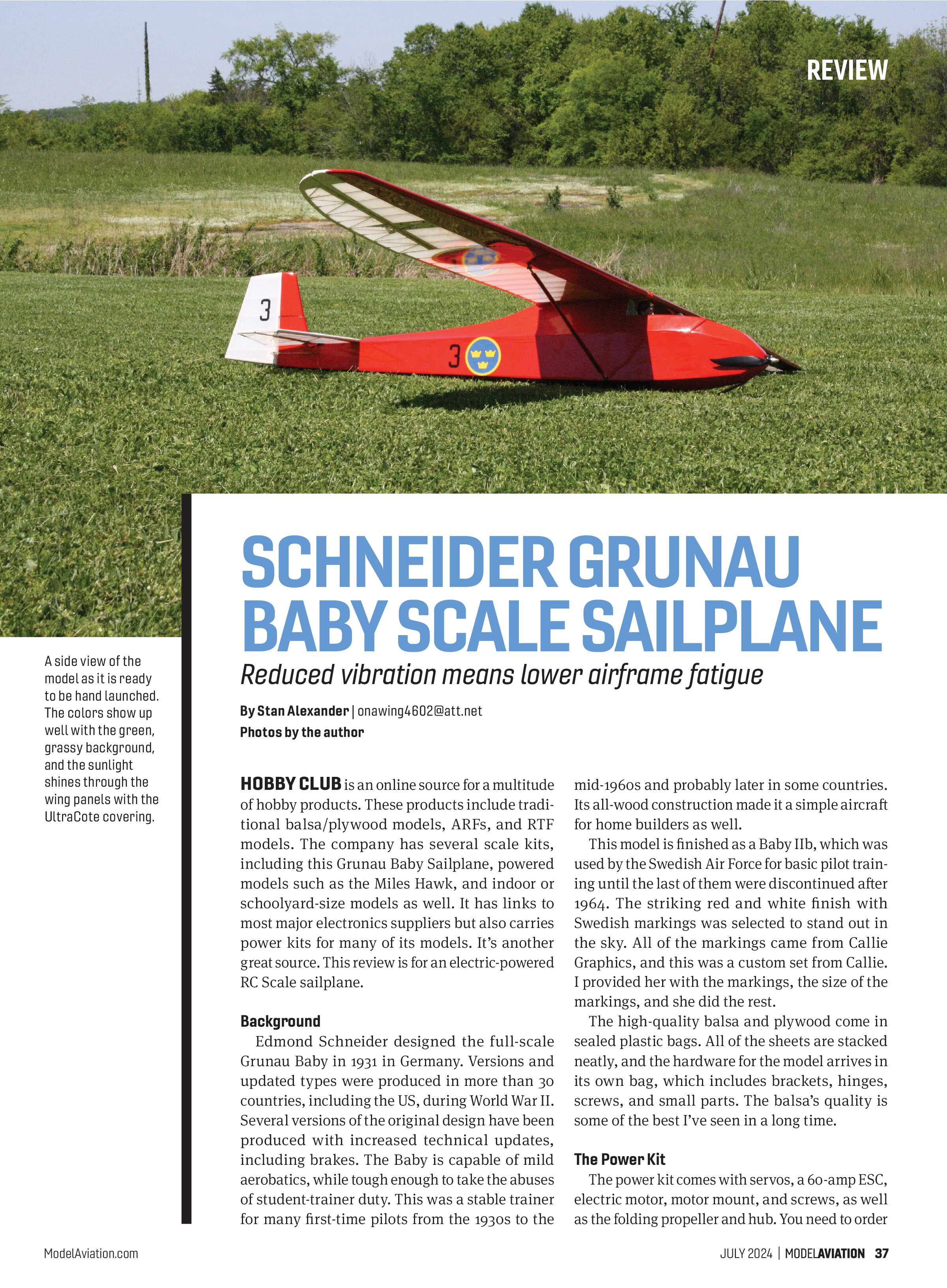
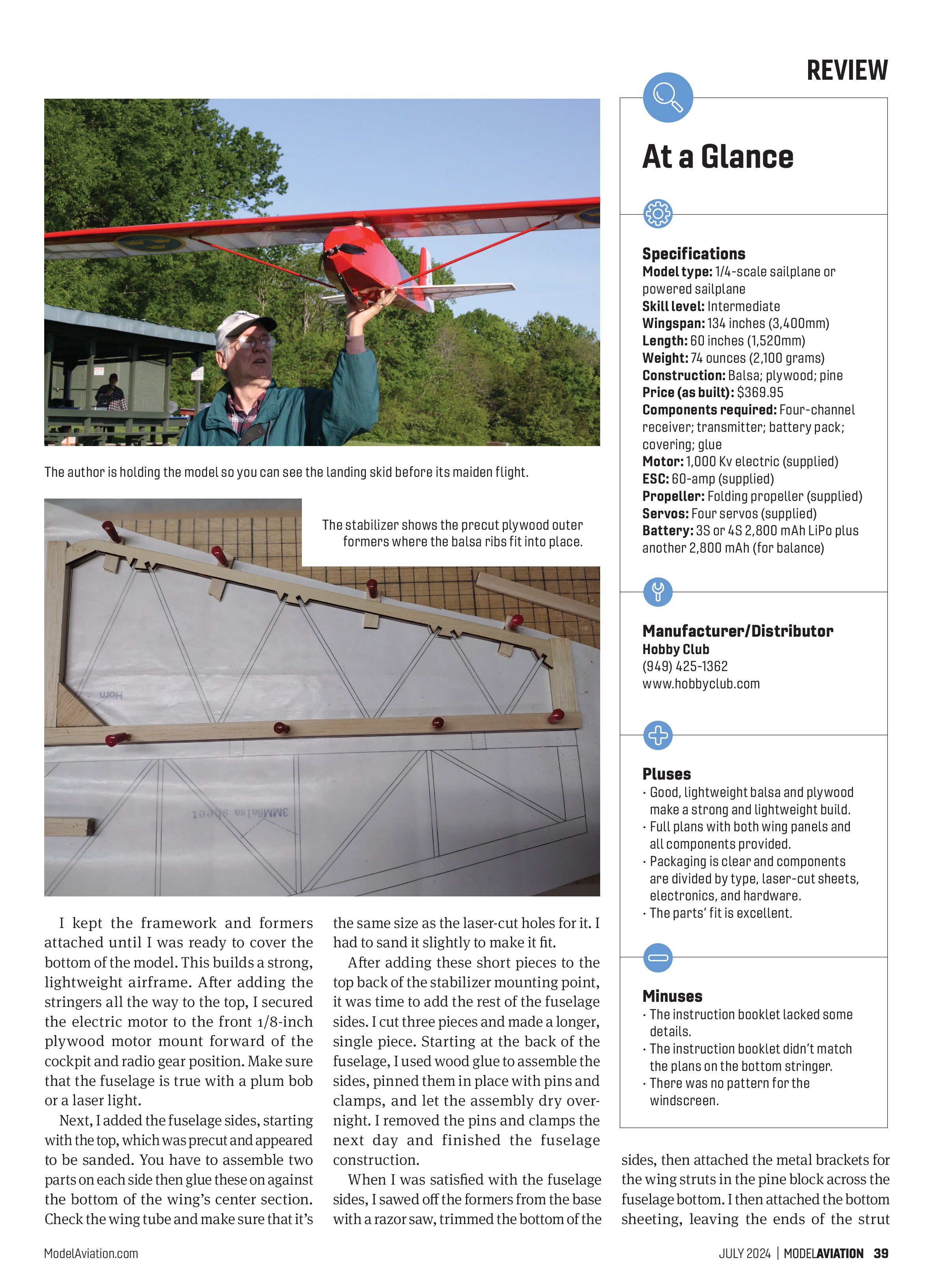
This model is finished as a Baby IIb, which was used by the Swedish Air Force for basic pilot training until the last of them were discontinued after 1964. The striking red and white finish with Swedish markings was selected to stand out in the sky. All of the markings came from Callie Graphics, and this was a custom set from Callie. I provided her with the markings, the size of the markings, and she did the rest.
The high-quality balsa and plywood come in sealed plastic bags. All of the sheets are stacked neatly, and the hardware for the model arrives in its own bag, which includes brackets, hinges, screws, and small parts. The balsa’s quality is some of the best I’ve seen in a long time.
The Power Kit
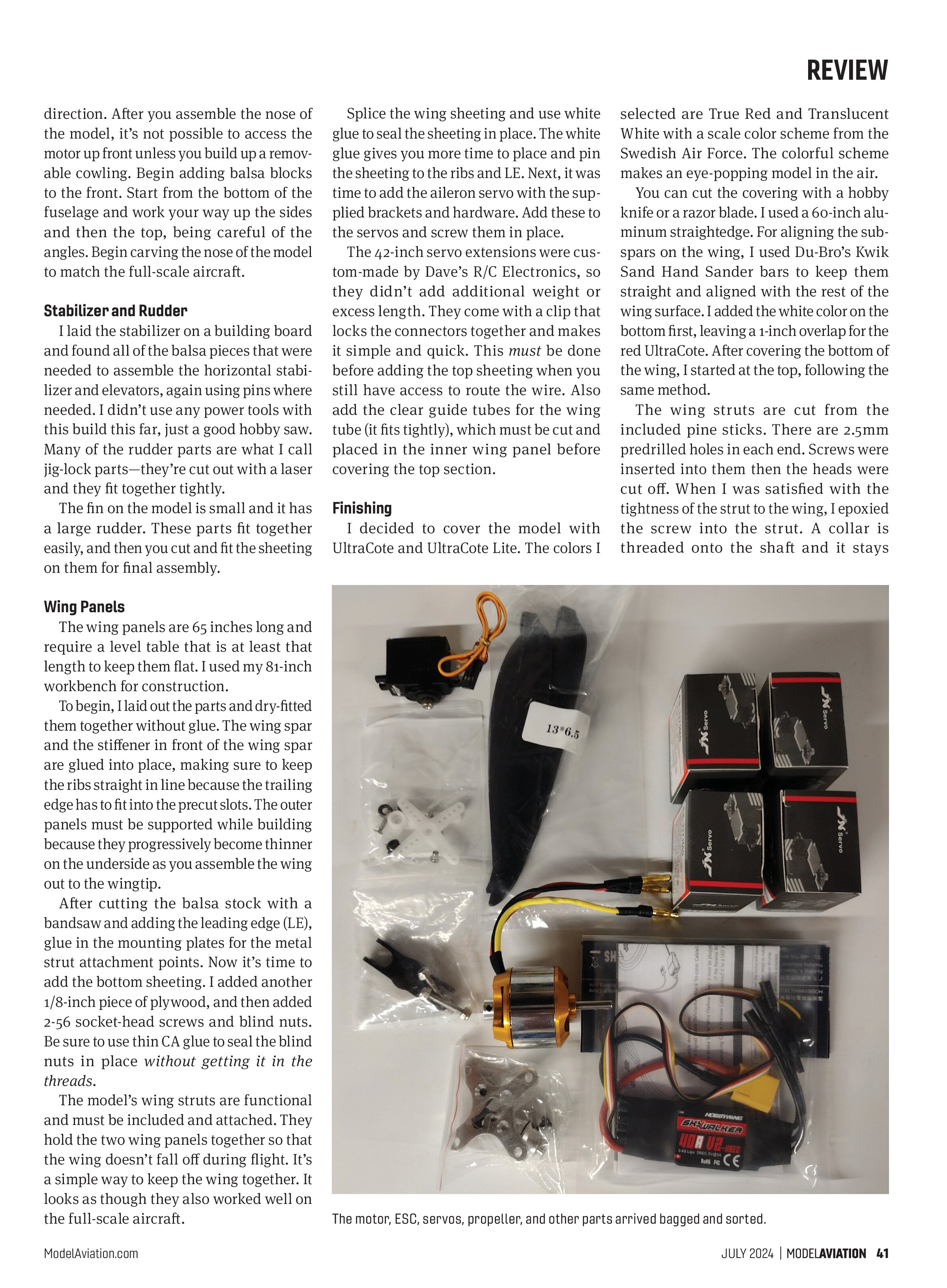
The power kit comes with servos, a 60-amp ESC, electric motor, motor mount, and screws, as well as the folding propeller and hub. You need to order
the servo extensions. I had mine cus-
tom-made at 42 inches by Dave’s R/C
Electronics. He also made an extended Y
connector for the aileron servos. This
extended Y connector gave me more room
to work with when plugging in the con-
nector to the receiver when it is mounted

through the wing center pod, as well as
the ailerons extensions that also feature
locking connectors.
Building the Fuselage
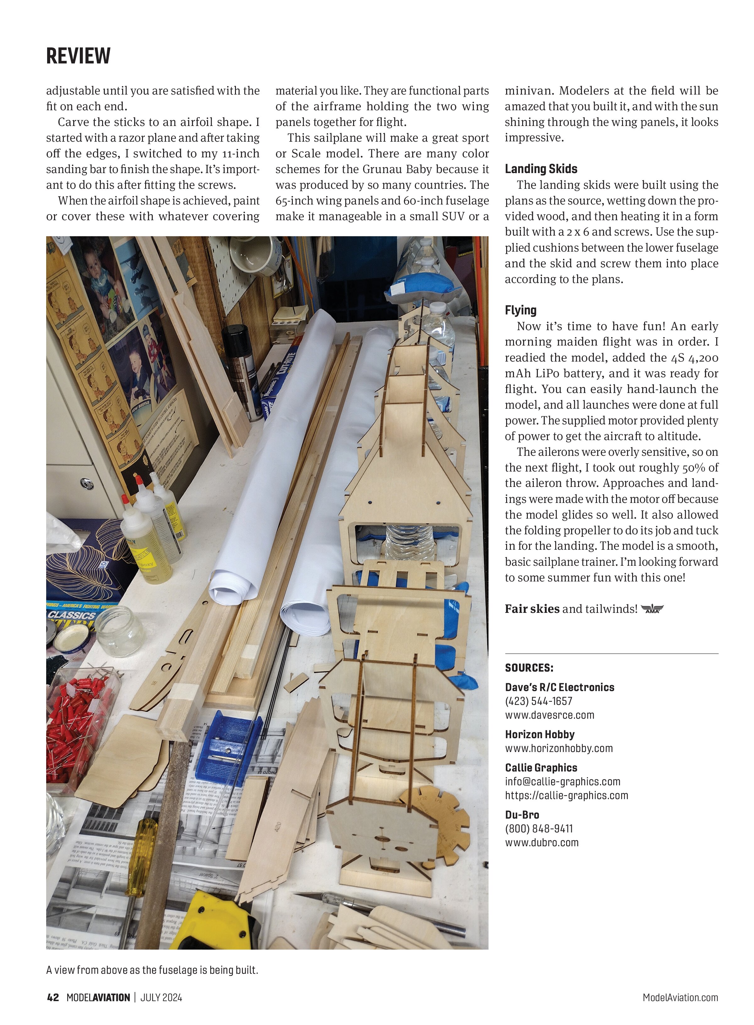
Building from the instructions, I started
with the fuselage. You need a 60-inch flat
surface with an unobstructed view. The
fuselage is built on a frame that is made onto
the formers for the fuselage. I added the
stringers to the fuselage, starting with the
bottom former and working my way up the
sides to ensure the fuselage didn’t warp
while under construction.

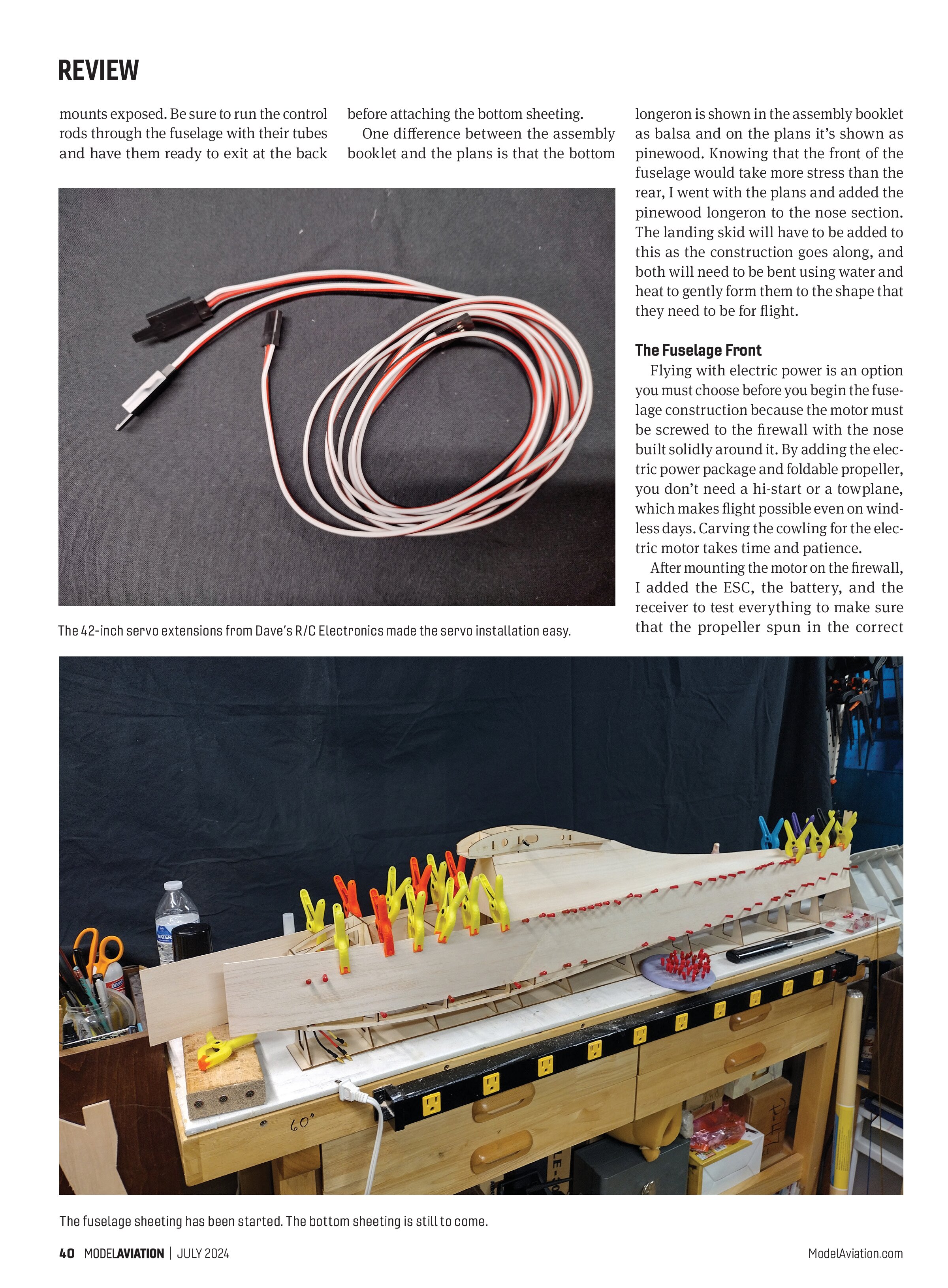
The author is holding the model so you can see the landing skid before its maiden flight.

The stabilizer shows the precut plywood outer formers where the balsa ribs fit into place.

I kept the framework and formers
attached until I was ready to cover the
bottom of the model. This builds a strong,
lightweight airframe. After adding the
stringers all the way to the top, I secured
the electric motor to the front 1/8-inch
plywood motor mount forward of the
cockpit and radio gear position. Make sure
that the fuselage is true with a plumb bob
or a laser light.
Next, I added the fuselage sides, starting
with the top, which was precut and appeared
to be sanded. You have to assemble two
parts on each side then glue these on against
the bottom of the wing’s center section.
Check the wing tube and make sure that it’s
the same size as the laser-cut holes for it. I
had to sand it slightly to make it fit.
After adding these short pieces to the
top back of the stabilizer mounting point,
it was time to add the rest of the fuselage
sides. I cut three pieces and made a longer,
single piece. Starting at the back of the
fuselage, I used wood glue to assemble the
sides, pinned them in place with pins and
clamps, and let the assembly dry over-
night. I removed the pins and clamps the
next day and finished the fuselage
construction.
When I was satisfied with the fuselage
sides, I sawed off the formers from the base
with a razor saw, trimmed the bottom of the
At a Glance
Specifications
Model type: 1/4-scale sailplane or powered sailplane
Skill level: Intermediate
Wingspan: 134 inches (3,400mm)
Length: 60 inches (1,520mm)
Weight: 74 ounces (2,100 grams)
Construction: Balsa; plywood; pine
Price (as built): $369.95
Components required: Four-channel receiver; transmitter; battery pack; covering; glue
Motor: 1,000 Kv electric (supplied)
ESC: 60-amp (supplied)
Propeller: Folding propeller (supplied)
Servos: Four servos (supplied)
Battery: 3S or 4S 2,800 mAh LiPo plus another 2,800 mAh (for balance)
Manufacturer/Distributor
Hobby Club
(949) 425-1362
www.hobbyclub.com
Pluses
- Good, lightweight balsa and plywood make a strong and lightweight build.
- Full plans with both wing panels and all components provided.
- Packaging is clear and components are divided by type, laser-cut sheets, electronics, and hardware.
- The parts’ fit is excellent.
Minuses
- The instruction booklet lacked some details.
- The instruction booklet didn’t match the plans on the bottom stringer.
- There was no pattern for the windscreen.
sides, then attached the metal brackets for
the wing struts in the pine block across the
fuselage bottom. I then attached the bottom
sheeting, leaving the ends of the strut
mounts exposed. Be sure to run the control rods through the fuselage with their tubes and have them ready to exit at the back before attaching the bottom sheeting.
One difference between the assembly booklet and the plans is that the bottom longeron is shown in the assembly booklet as balsa and on the plans it’s shown as pinewood. Knowing that the front of the fuselage would take more stress than the rear, I went with the plans and added the pinewood longeron to the nose section. The landing skid will have to be added to this as the construction goes along, and both will need to be bent using water and heat to gently form them to the shape that they need to be for flight.
The Fuselage Front
Flying with electric power is an option you must choose before you begin the fuselage construction because the motor must be screwed to the firewall with the nose built solidly around it. By adding the electric power package and foldable propeller, you don’t need a hi-start or a towplane, which makes flight possible even on windless days. Carving the cowling for the electric motor takes time and patience.
After mounting the motor on the firewall, I added the ESC, the battery, and the receiver to test everything to make sure that the propeller spun in the correct direction. After you assemble the nose of the model, it’s not possible to access the motor up front unless you build up a removable cowling. Begin adding balsa blocks to the front. Start from the bottom of the fuselage and work your way up the sides and then the top, being careful of the angles. Begin carving the nose of the model to match the full-scale aircraft.
Stabilizer and Rudder
I laid the stabilizer on a building board and found all of the balsa pieces that were needed to assemble the horizontal stabilizer and elevators, again using pins where needed. I didn’t use any power tools with this build this far, just a good hobby saw. Many of the rudder parts are what I call jig-lock parts—they’re cut out with a laser and they fit together tightly.
The fin on the model is small and it has a large rudder. These parts fit together easily, and then you cut and fit the sheeting on them for final assembly.
Wing Panels
The wing panels are 65 inches long and require a level table that is at least that length to keep them flat. I used my 81-inch workbench for construction.
To begin, I laid out the parts and dry-fitted them together without glue. The wing spar and the stiffener in front of the wing spar are glued into place, making sure to keep the ribs straight in line because the trailing edge has to fit into the precut slots. The outer panels must be supported while building because they progressively become thinner on the underside as you assemble the wing out to the wingtip.
After cutting the balsa stock with a bandsaw and adding the leading edge (LE), glue in the mounting plates for the metal strut attachment points. Now it’s time to add the bottom sheeting. I added another 1/8-inch piece of plywood, and then added 2-56 socket-head screws and blind nuts. Be sure to use thin CA glue to seal the blind nuts in place without getting it in the threads.
The model’s wing struts are functional and must be included and attached. They hold the two wing panels together so that the wing doesn’t fall off during flight. It’s a simple way to keep the wing together. It looks as though they also worked well on the full-scale aircraft.
Splice the wing sheeting and use white glue to seal the sheeting in place. The white glue gives you more time to place and pin the sheeting to the ribs and LE. Next, it was time to add the aileron servo with the supplied brackets and hardware. Add these to the servos and screw them in place.
The 42-inch servo extensions were custom-made by Dave’s R/C Electronics, so they didn’t add additional weight or excess length. They come with a clip that locks the connectors together and makes it simple and quick. This must be done before adding the top sheeting when you still have access to route the wire. Also add the clear guide tubes for the wing tube (it fits tightly), which must be cut and placed in the inner wing panel before covering the top section.
Finishing
I decided to cover the model with UltraCote and UltraCote Lite. The colors I selected are True Red and Translucent White with a scale color scheme from the Swedish Air Force. The colorful scheme makes an eye-popping model in the air.
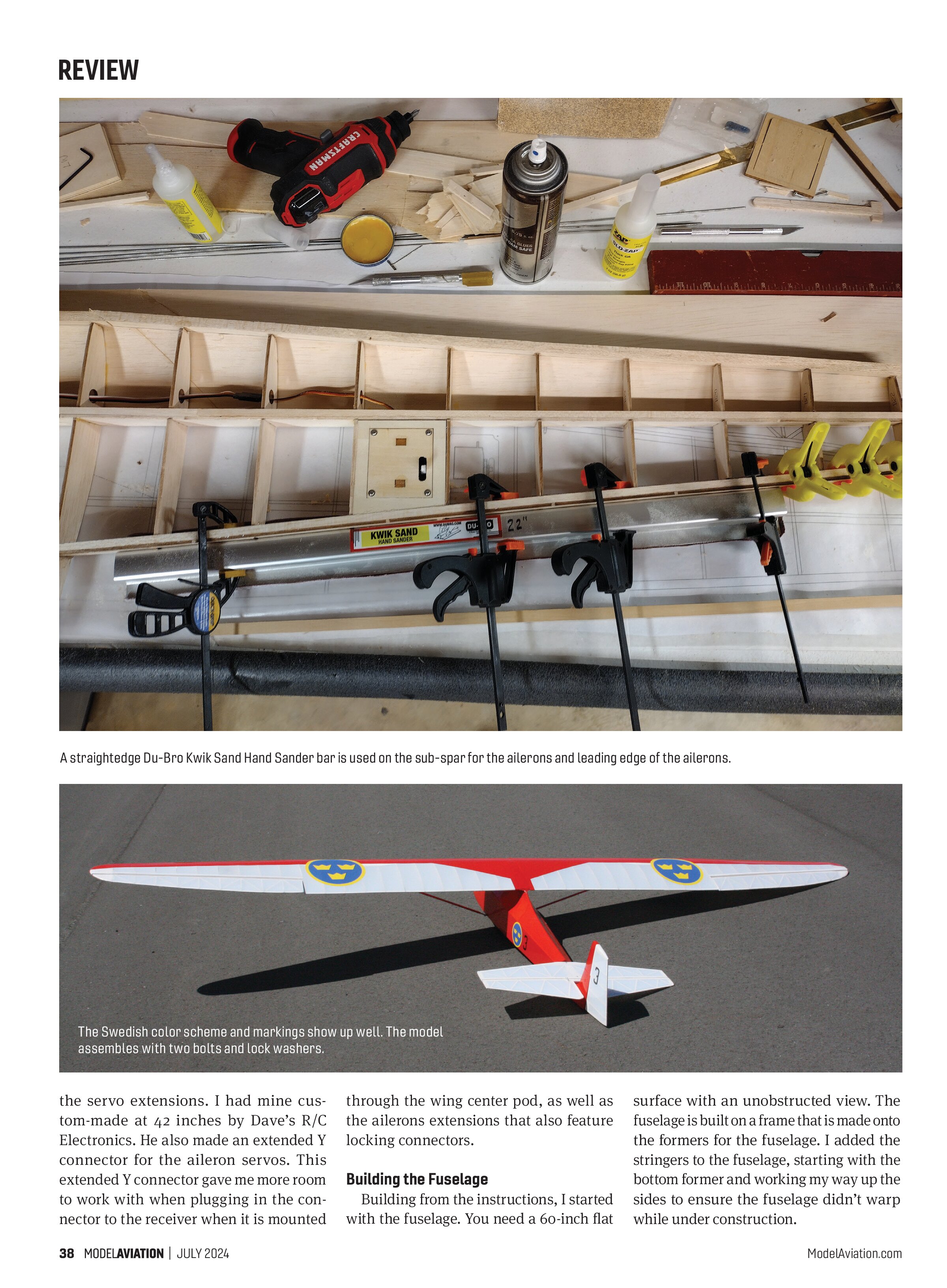
You can cut the covering with a hobby knife or a razor blade. I used a 60-inch aluminum straightedge. For aligning the sub-spars on the wing, I used Du-Bro’s Kwik Sand Hand Sander bars to keep them straight and aligned with the rest of the wing surface. I added the white color on the bottom first, leaving a 1-inch overlap for the red UltraCote. After covering the bottom of the wing, I started at the top, following the same method.
The wing struts are cut from the included pine sticks. There are 2.5mm predrilled holes in each end. Screws were inserted into them then the heads were cut off. When I was satisfied with the tightness of the strut to the wing, I epoxied the screw into the strut. A collar is threaded onto the shaft and it stays


adjustable until you are satisfied with the fit on each end.
Carve the sticks to an airfoil shape. I started with a razor plane and after taking off the edges, I switched to my 11-inch sanding bar to finish the shape. It’s important to do this after fitting the screws.
When the airfoil shape is achieved, paint or cover these with whatever covering material you like. They are functional parts of the airframe holding the two wing panels together for flight.
This sailplane will make a great sport or Scale model. There are many color schemes for the Grunau Baby because it was produced by so many countries. The 65-inch wing panels and 60-inch fuselage make it manageable in a small SUV or a

minivan. Modelers at the field will be amazed that you built it, and with the sun shining through the wing panels, it looks impressive.
Landing Skids
The landing skids were built using the plans as the source, wetting down the provided wood, and then heating it in a form built with a 2 x 6 and screws. Use the supplied cushions between the lower fuselage and the skid and screw them into place according to the plans.
Flying
Now it’s time to have fun! An early morning maiden flight was in order. I readied the model, added the 4S 4,200 mAh LiPo battery, and it was ready for flight. You can easily hand-launch the model, and all launches were done at full power. The supplied motor provided plenty of power to get the aircraft to altitude.
The ailerons were overly sensitive, so on the next flight, I took out roughly 50% of the aileron throw. Approaches and landings were made with the motor off because the model glides so well. It also allowed the folding propeller to do its job and tuck in for the landing. The model is a smooth, basic sailplane trainer. I’m looking forward to some summer fun with this one!
Fair skies and tailwinds!
SOURCES:
Dave’s R/C Electronics
(423) 544-1657
www.davesrce.com
Horizon Hobby
www.horizonhobby.com
Callie Graphics
info@callie-graphics.com
https://callie-graphics.com
Du-Bro
(800) 848-9411
www.dubro.com