SETTING UP A TURBINE JET
Learning the basics
By Jonathan Vogt
thelighter sideofrc@gmail.com
Photos provided by the author
Whether it’s your first turbine aircraft or your ninth turbine aircraft, setting it up can be a daunting task to accomplish. The modern technology that’s available in the hobby is exceptional, but it can still be an overwhelming task to ensure that all of the systems are talking to each other and working harmoniously. Systems and processes involved in putting an aircraft together are extremely helpful to keep organized. This article’s goal is to share an overview of the systems in a modern turbine aircraft. Because there are so many variations in equipment choices, I will keep it general. If you have questions, your best course is to refer to the manual, reach out to the manufacturer, or seek advice from an experienced source.
I had a friend help me with this project so that I could concentrate on recording each step as we went.
The Aircraft
I will go through this in the same way that we complete a build in the shop. The first thing we think about is the complete aircraft. Although you might be lost if this is your first turbine aircraft, planning all of the equipment in advance will help with the construction.
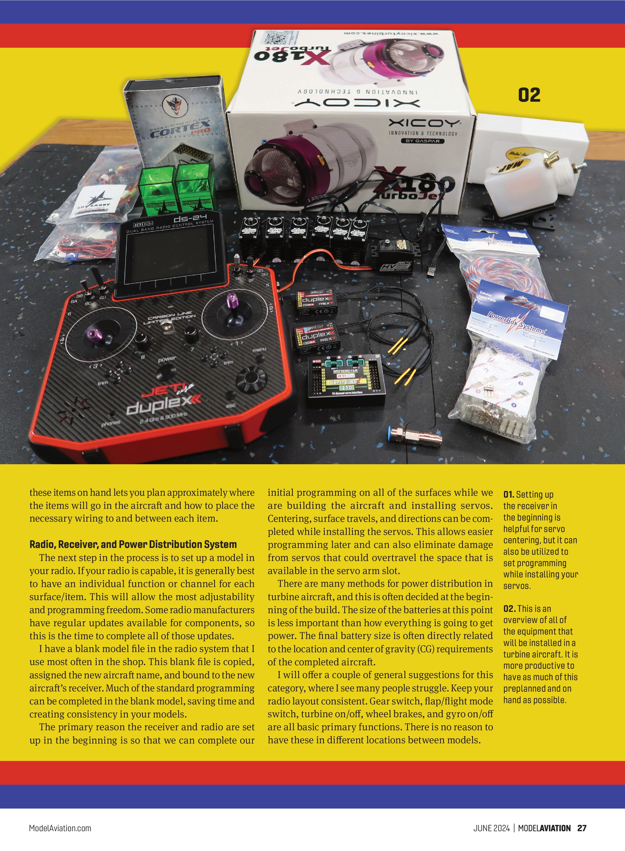
Before we start an aircraft build, we generally have nearly all of the equipment on hand. Part of this stems from not wanting to wait for parts to arrive and knowing what turbine(s), servos, wiring, lights, air system, receivers, power distribution, gyro, Ultimate Air Trap (UAT) bubble traps, and fuel systems we will be using in the aircraft. Having

these items on hand lets you plan approximately where the items will go in the aircraft and how to place the necessary wiring to and between each item.
Radio, Receiver, and Power Distribution System
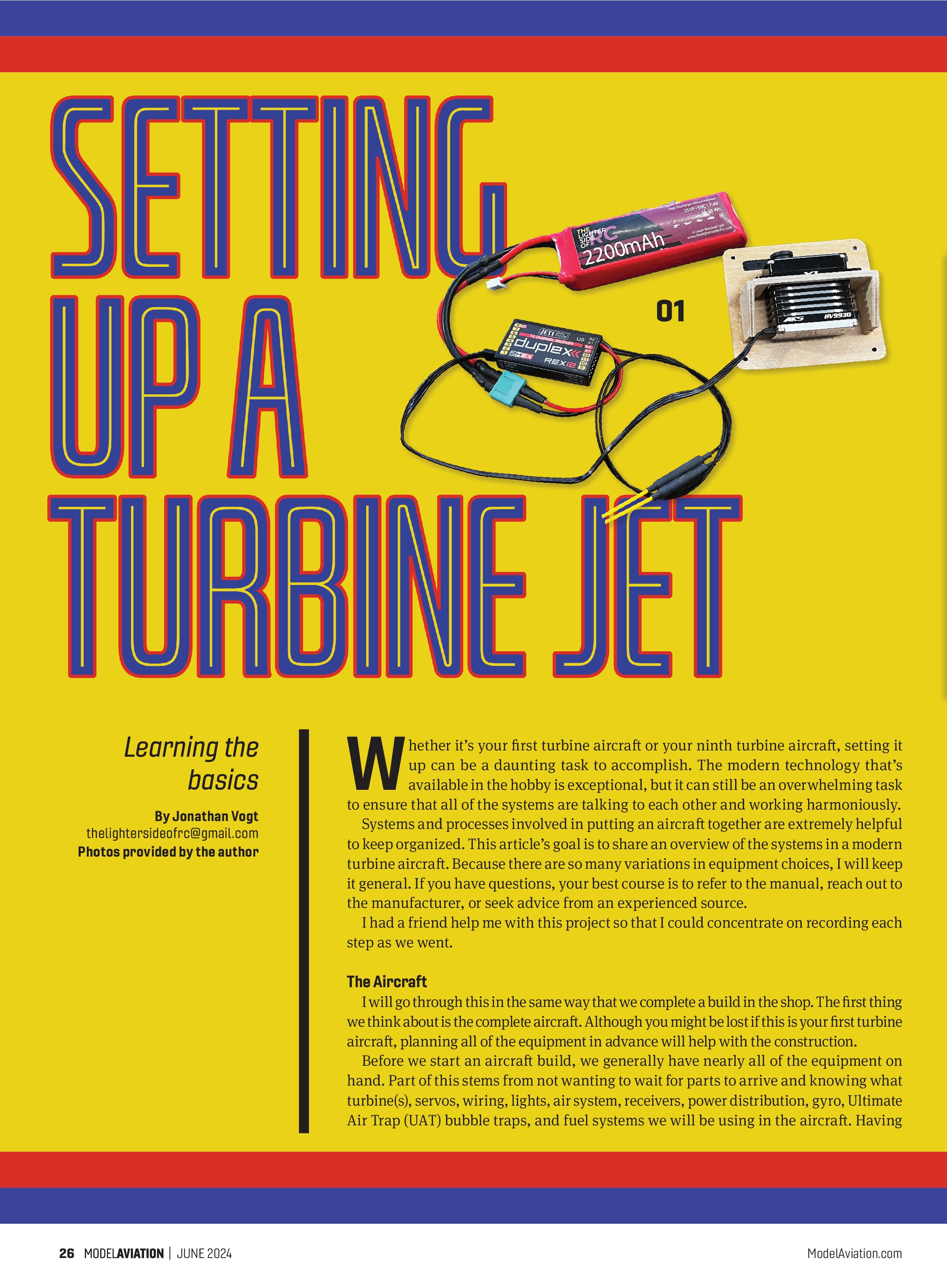
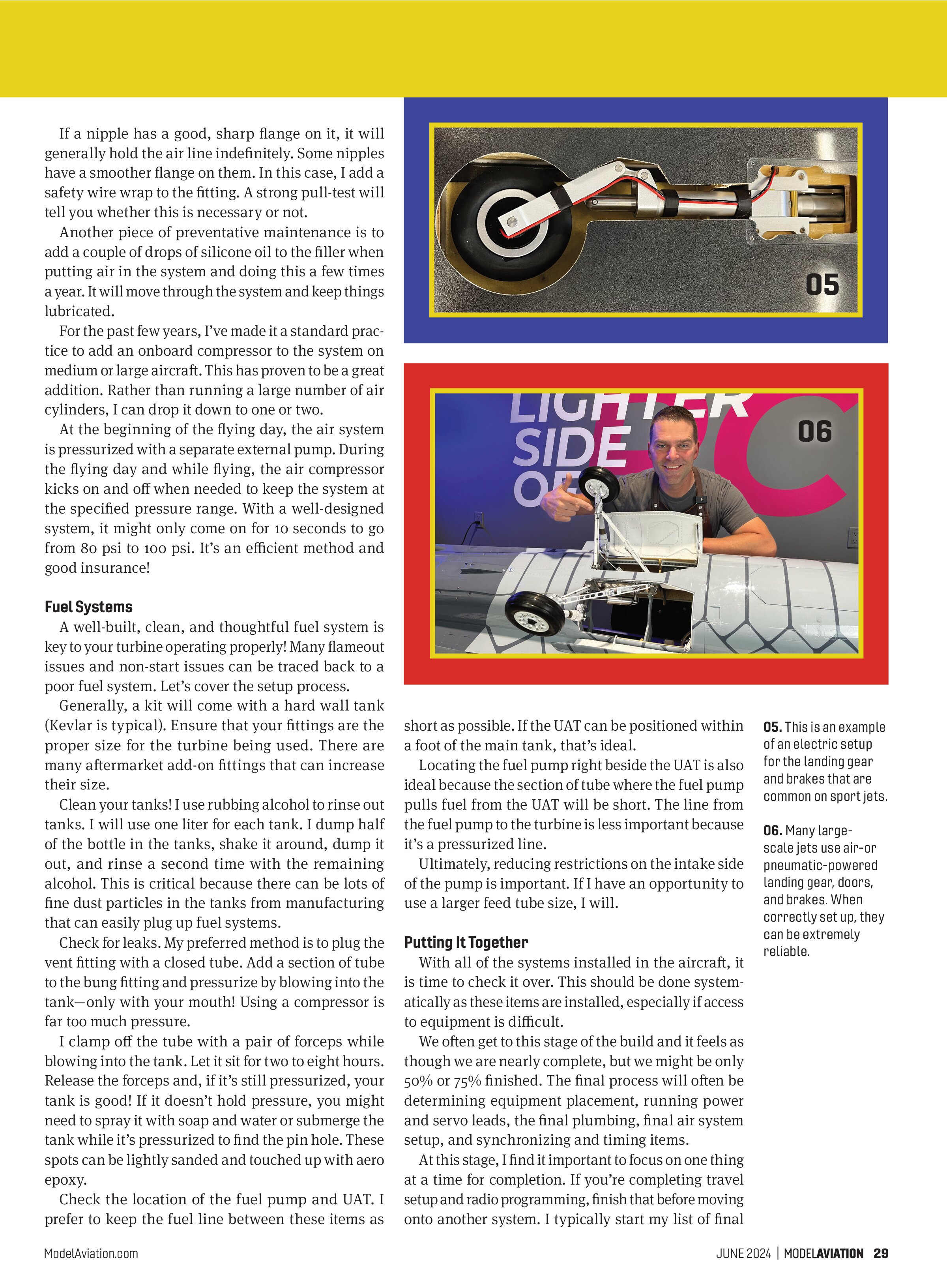
The next step in the process is to set up a model in your radio. If your radio is capable, it is generally best to have an individual function or channel for each surface/item. This will allow the most adjustability and programming freedom. Some radio manufacturers have regular updates available for components, so this is the time to complete all of those updates.
I have a blank model file in the radio system that I use most often in the shop. This blank file is copied, assigned the new aircraft name, and bound to the new aircraft’s receiver. Much of the standard programming can be completed in the blank model, saving time and creating consistency in your models.
The primary reason the receiver and radio are set up in the beginning is so that we can complete our initial programming on all of the surfaces while we are building the aircraft and installing servos. Centering, surface travels, and directions can be completed while installing the servos. This allows easier programming later and can also eliminate damage from servos that could overtravel the space that is available in the servo arm slot.
There are many methods for power distribution in turbine aircraft, and this is often decided at the beginning of the build. The size of the batteries at this point is less important than how everything is going to get power. The final battery size is often directly related to the location and center of gravity (CG) requirements of the completed aircraft.
I will offer a couple of general suggestions for this category, where I see many people struggle. Keep your radio layout consistent. Gear switch, flap/flight mode switch, turbine on/off, wheel brakes, and gyro on/off are all basic primary functions. There is no reason to have these in different locations between models.

A pilot should be able to operate these basic functions on the radio without looking down. If you look down for a moment, your turbine aircraft can be in a much different location in the sky when you look back up, which can be a problem!
Keep your setup consistent. If we have set up two ailerons on an aircraft, these are often labeled on the radio as Ail 1 and Ail 2. Our setups are always left to right, so Ail 1 is left and Ail 2 is right. On a twin turbine with Throttle 1 and Throttle 2, the same applies. Throttle 1 is the left turbine and Throttle 2 is the right turbine. This is helpful for future troubleshooting or adjustments.

Interference is still a thing! I lost an expensive model a year ago because two devices were placed closely together and caused interference. With modern radio systems, there tends to be some complacency with this setup, so be mindful of this.
Control System
For most aircraft, the servos are tied to the flight controls and any other additional items. Ensuring that your servos are an appropriate size and have the proper power needed should be completed in the planning stage. If you’re using a power distribution system that is outputting straight two-cell LiPo voltage, make sure that your servos are suitable for this voltage.
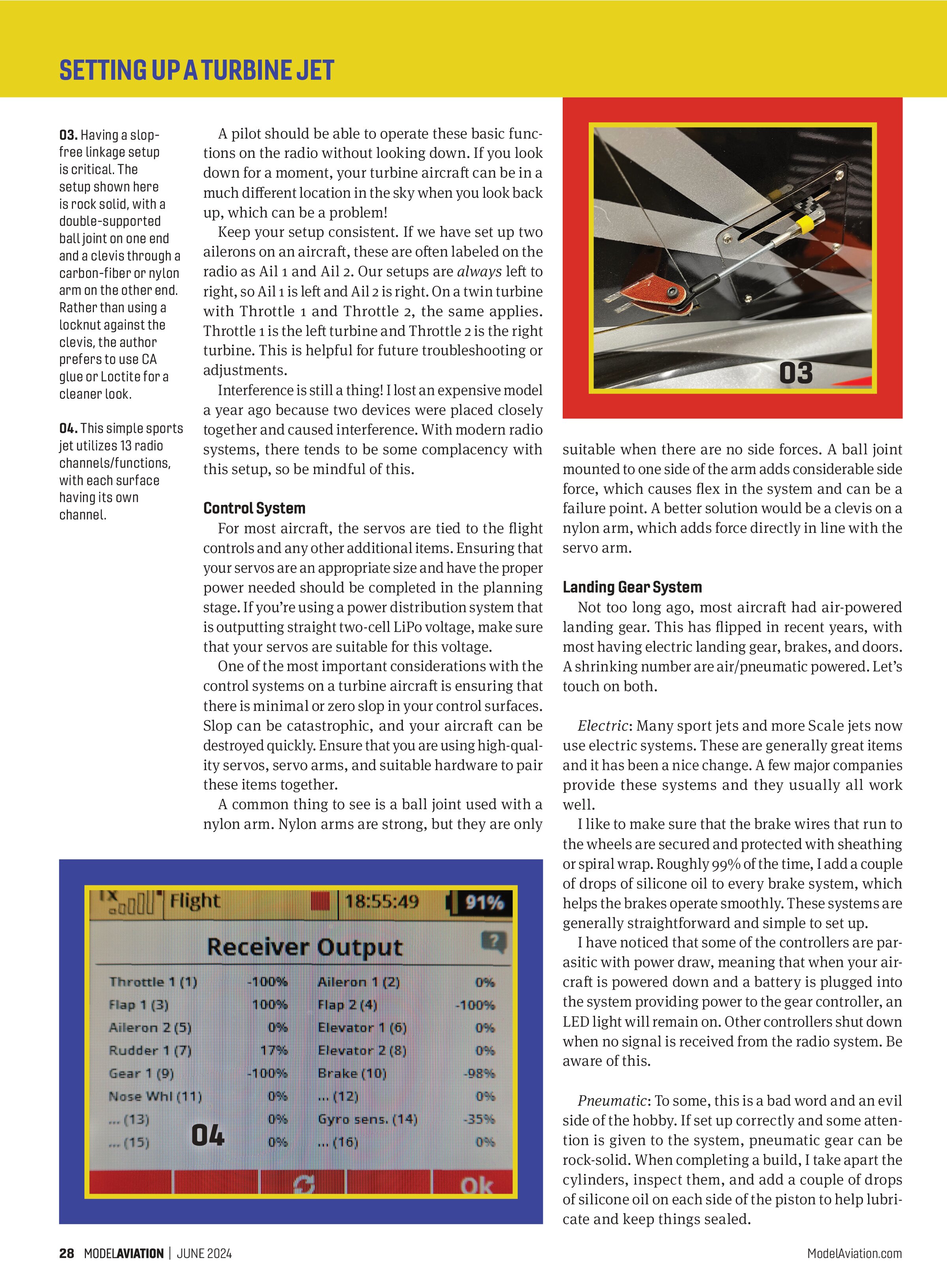
One of the most important considerations with the control systems on a turbine aircraft is ensuring that there is minimal or zero slop in your control surfaces. Slop can be catastrophic, and your aircraft can be destroyed quickly. Ensure that you are using high-quality servos, servo arms, and suitable hardware to pair these items together.
A common thing to see is a ball joint used with a nylon arm. Nylon arms are strong, but they are only suitable when there are no side forces. A ball joint mounted to one side of the arm adds considerable side force, which causes flex in the system and can be a failure point. A better solution would be a clevis on a nylon arm, which adds force directly in line with the servo arm.

Landing Gear System
Not too long ago, most aircraft had air-powered landing gear. This has flipped in recent years, with most having electric landing gear, brakes, and doors. A shrinking number are air/pneumatic powered. Let’s touch on both.
Electric: Many sport jets and more Scale jets now use electric systems. These are generally great items and it has been a nice change. A few major companies provide these systems and they usually all work well.
I like to make sure that the brake wires that run to the wheels are secured and protected with sheathing or spiral wrap. Roughly 99% of the time, I add a couple of drops of silicone oil to every brake system, which helps the brakes operate smoothly. These systems are generally straightforward and simple to set up.
I have noticed that some of the controllers are parasitic with power draw, meaning that when your aircraft is powered down and a battery is plugged into the system providing power to the gear controller, an LED light will remain on. Other controllers shut down when no signal is received from the radio system. Be aware of this.
Pneumatic: To some, this is a bad word and an evil side of the hobby. If set up correctly and some attention is given to the system, pneumatic gear can be rock-solid. When completing a build, I take apart the cylinders, inspect them, and add a couple of drops of silicone oil on each side of the piston to help lubricate and keep things sealed.
If a nipple has a good, sharp flange on it, it will generally hold the air line indefinitely. Some nipples have a smoother flange on them. In this case, I add a safety wire wrap to the fitting. A strong pull-test will tell you whether this is necessary or not.
Another piece of preventative maintenance is to add a couple of drops of silicone oil to the filler when putting air in the system and doing this a few times a year. It will move through the system and keep things lubricated.

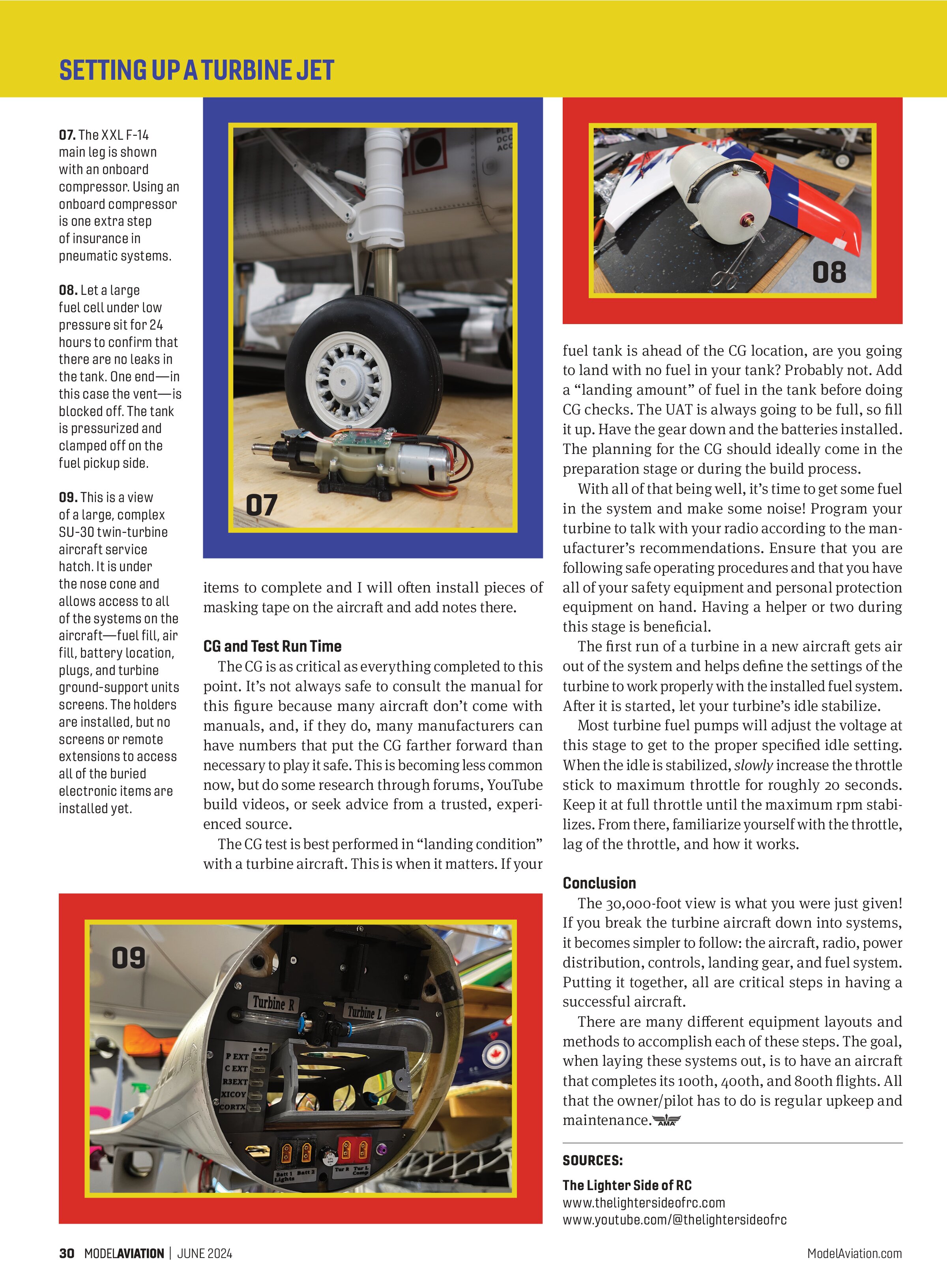
For the past few years, I’ve made it a standard practice to add an onboard compressor to the system on medium or large aircraft. This has proven to be a great addition. Rather than running a large number of air cylinders, I can drop it down to one or two.
At the beginning of the flying day, the air system is pressurized with a separate external pump. During the flying day and while flying, the air compressor kicks on and off when needed to keep the system at the specified pressure range. With a well-designed system, it might only come on for 10 seconds to go from 80 psi to 100 psi. It’s an efficient method and good insurance!
Fuel Systems
A well-built, clean, and thoughtful fuel system is key to your turbine operating properly! Many flameout issues and non-start issues can be traced back to a poor fuel system. Let’s cover the setup process.
Generally, a kit will come with a hard wall tank (Kevlar is typical). Ensure that your fittings are the proper size for the turbine being used. There are many aftermarket add-on fittings that can increase their size.
Clean your tanks! I use rubbing alcohol to rinse out tanks. I will use one liter for each tank. I dump half of the bottle in the tanks, shake it around, dump it out, and rinse a second time with the remaining alcohol. This is critical because there can be lots of fine dust particles in the tanks from manufacturing that can easily plug up fuel systems.
Check for leaks. My preferred method is to plug the vent fitting with a closed tube. Add a section of tube to the bung fitting and pressurize by blowing into the tank—only with your mouth! Using a compressor is far too much pressure.
I clamp off the tube with a pair of forceps while blowing into the tank. Let it sit for two to eight hours. Release the forceps and, if it’s still pressurized, your tank is good! If it doesn’t hold pressure, you might need to spray it with soap and water or submerge the tank while it’s pressurized to find the pin hole. These spots can be lightly sanded and touched up with aero epoxy.
Check the location of the fuel pump and UAT. I prefer to keep the fuel line between these items as short as possible. If the UAT can be positioned within a foot of the main tank, that’s ideal.
Locating the fuel pump right beside the UAT is also ideal because the section of tube where the fuel pump pulls fuel from the UAT will be short. The line from the fuel pump to the turbine is less important because it’s a pressurized line.
Ultimately, reducing restrictions on the intake side of the pump is important. If I have an opportunity to use a larger feed tube size, I will.

Putting It Together
With all of the systems installed in the aircraft, it is time to check it over. This should be done systematically as these items are installed, especially if access to equipment is difficult.
We often get to this stage of the build and it feels as though we are nearly complete, but we might be only 50% or 75% finished. The final process will often be determining equipment placement, running power and servo leads, the final plumbing, final air system setup, and synchronizing and timing items.
At this stage, I find it important to focus on one thing at a time for completion. If you’re completing travel setup and radio programming, finish that before moving onto another system. I typically start my list of final


items to complete and I will often install pieces of masking tape on the aircraft and add notes there.
CG and Test Run Time
The CG is as critical as everything completed to this point. It’s not always safe to consult the manual for this figure because many aircraft don’t come with manuals, and, if they do, many manufacturers can have numbers that put the CG farther forward than necessary to play it safe. This is becoming less common now, but do some research through forums, YouTube build videos, or seek advice from a trusted, experienced source.
The CG test is best performed in “landing condition” with a turbine aircraft. This is when it matters. If your fuel tank is ahead of the CG location, are you going to land with no fuel in your tank? Probably not. Add a “landing amount” of fuel in the tank before doing CG checks. The UAT is always going to be full, so fill it up. Have the gear down and the batteries installed. The planning for the CG should ideally come in the preparation stage or during the build process.
With all of that being well, it’s time to get some fuel in the system and make some noise! Program your turbine to talk with your radio according to the manufacturer’s recommendations. Ensure that you are following safe operating procedures and that you have all of your safety equipment and personal protection equipment on hand. Having a helper or two during this stage is beneficial.
The first run of a turbine in a new aircraft gets air out of the system and helps define the settings of the turbine to work properly with the installed fuel system. After it is started, let your turbine’s idle stabilize.
Most turbine fuel pumps will adjust the voltage at this stage to get to the proper specified idle setting. When the idle is stabilized, slowly increase the throttle stick to maximum throttle for roughly 20 seconds. Keep it at full throttle until the maximum rpm stabilizes. From there, familiarize yourself with the throttle, lag of the throttle, and how it works.
Conclusion
The 30,000-foot view is what you were just given! If you break the turbine aircraft down into systems, it becomes simpler to follow: the aircraft, radio, power distribution, controls, landing gear, and fuel system. Putting it together, all are critical steps in having a successful aircraft.
There are many different equipment layouts and methods to accomplish each of these steps. The goal, when laying these systems out, is to have an aircraft that completes its 100th, 400th, and 800th flights. All that the owner/pilot has to do is regular upkeep and maintenance.
SOURCES:
The Lighter Side of RC
www.thelightersideofrc.com
www.youtube.com/@thelightersideofrc