E1000 EVOLUTION
By Heath Bartel | heath.bartel@gmail.com

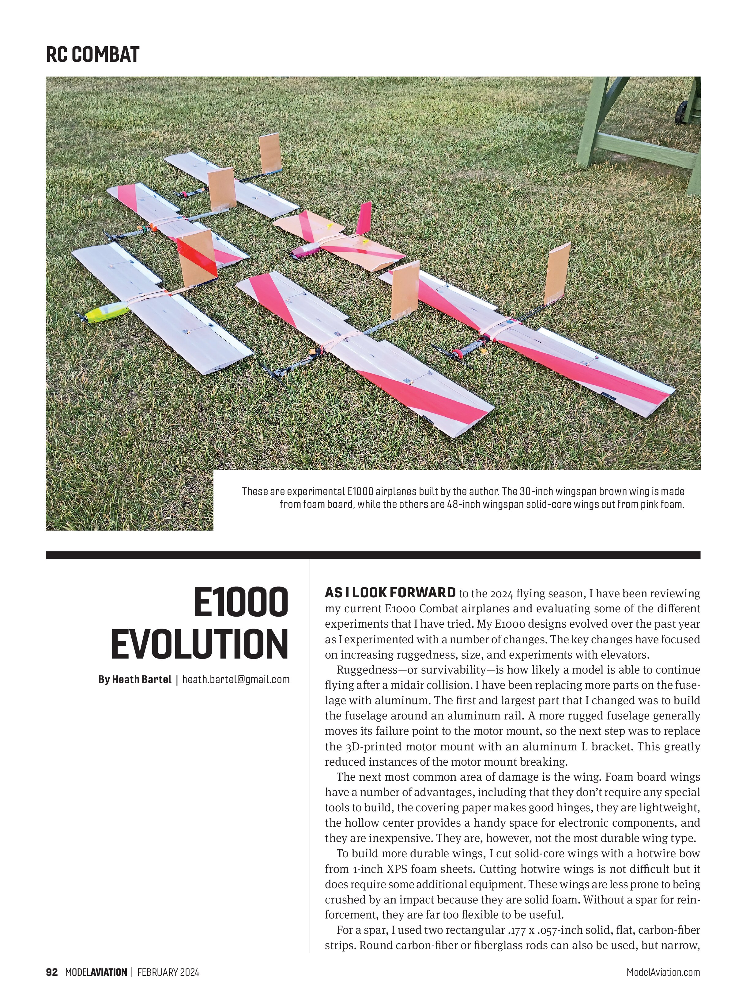
AS I LOOK FORWARD to the 2024 flying season, I have been reviewing my current E1000 Combat airplanes and evaluating some of the different experiments that I have tried. My E1000 designs evolved over the past year as I experimented with a number of changes. The key changes have focused on increasing ruggedness, size, and experiments with elevators.
Ruggedness—or survivability—is how likely a model is able to continue flying after a midair collision. I have been replacing more parts on the fuselage with aluminum. The first and largest part that I changed was to build the fuselage around an aluminum rail. A more rugged fuselage generally moves its failure point to the motor mount, so the next step was to replace the 3D-printed motor mount with an aluminum L bracket. This greatly reduced instances of the motor mount breaking.
The next most common area of damage is the wing. Foam board wings have a number of advantages, including that they don’t require any special tools to build, the covering paper makes good hinges, they are lightweight, the hollow center provides a handy space for electronic components, and they are inexpensive. They are, however, not the most durable wing type.
To build more durable wings, I cut solid-core wings with a hotwire bow from 1-inch XPS foam sheets. Cutting hotwire wings is not difficult but it does require some additional equipment. These wings are less prone to being crushed by an impact because they are solid foam. Without a spar for reinforcement, they are far too flexible to be useful.
For a spar, I used two rectangular .177 X .057-inch solid, flat, carbon-fiber strips. Round carbon-fiber or fiberglass rods can also be used, but narrow, flat, carbon-fiber strips are easier to install and provide greater resistance to bending loads for a given weight of carbon fiber.
Because the wing core is a solid block of foam, cavities for servos, the receiver, and any wires need to be cut into the wing before it’s covered. To improve surface strength and prevent twisting, the wing is covered in fiber-reinforced packing tape. A layer of colored packing tape adds differing colors and patterns to the top and bottom of the wing.
Armed with my new, stronger, stiffer wings, I began by breaking my 3D-printed hold downs. To stop this, I switched to steel rods that are easily stronger than both the wing and fuselage. The battery tray and wing saddle are 3D-printed from a semi-flexible thermoplastic polyurethane (TPU) that has a nice texture. Because the aluminum rail provides stiffness, these parts don’t need to be rigid. Alternatively, if I did not have a 3D printer, these parts could be cut from foam blocks.
I also increased the size of the E1000 airplanes. My past designs were based on a 30-inch wing, while the newer designs use a 48-inch wing. The larger wing improves the turning radius and provides a larger target to catch streamers. The tradeoff is that the top speed is slightly reduced versus the smaller wings. Because of this tradeoff, I think that 48 inches is at the upper end of what is practical, given the available power in this class. Along with the larger wing, I increased the length of the fuselage to 24 inches to allow a larger tail to be placed farther back from the wing.

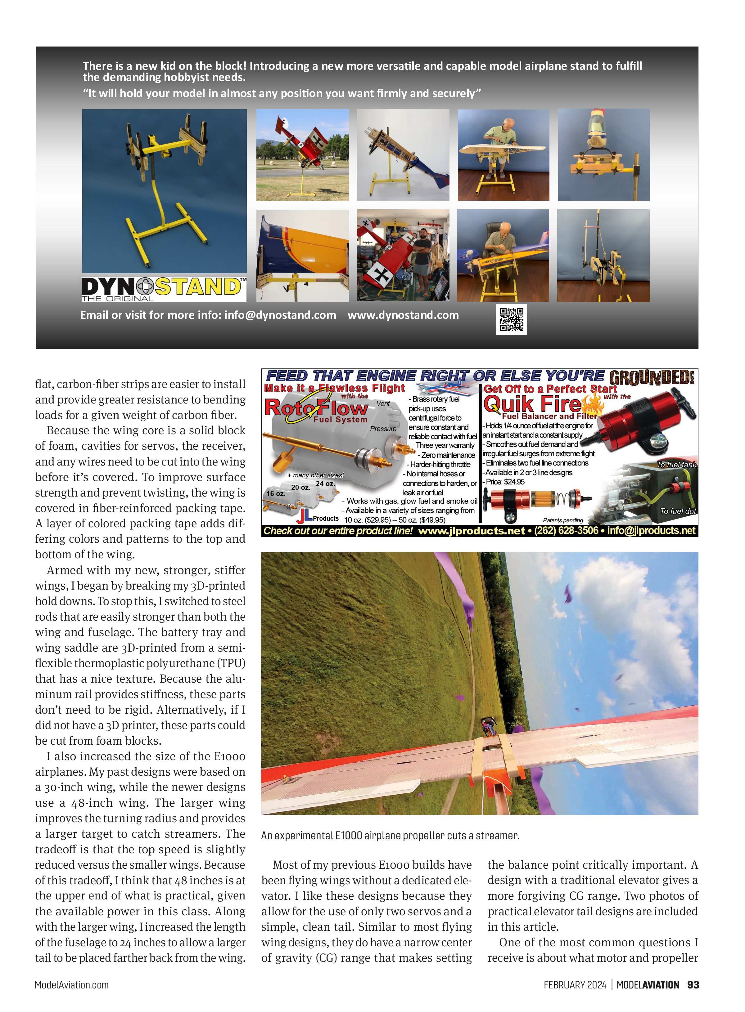
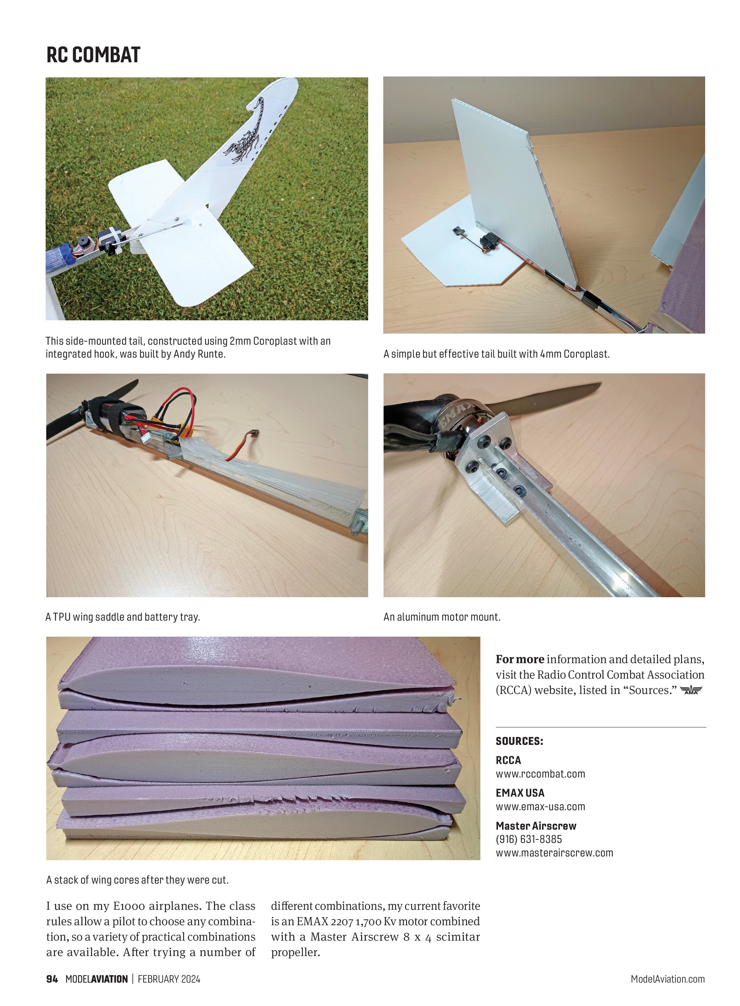
Most of my previous E1000 builds have been flying wings without a dedicated elevator. I like these designs because they allow for the use of only two servos and a simple, clean tail. Similar to most flying wing designs, they do have a narrow center of gravity (CG) range that makes setting the balance point critically important. A design with a traditional elevator gives a more forgiving CG range. Two photos of practical elevator tail designs are included in this article.
One of the most common questions I receive is about what motor and propeller


For more information and detailed plans, visit the Radio Control Combat Association (RCCA) website, listed in “Sources.”
SOURCES:
RCCA
www.rccombat.com
EMAX USA
www.emax-usa.com
Master Airscrew
(916) 631-8385
www.masterairscrew.com
I use on my E1000 airplanes. The class rules allow a pilot to choose any combination, so a variety of practical combinations are available. After trying a number of different combinations, my current favorite is an EMAX 2207 1,700 Kv motor combined with a Master Airscrew 8 x 4 scimitar propeller.