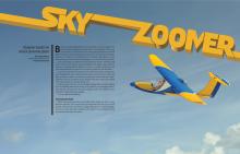
Sky Zoomer
Designer builds his
dream powered glider
By Clark Salisbury
clarksalisbury@hotmail.com
Photos by the author

Before we start building this RC-powered glider, I need to explain why I even wanted to design an airplane such as this. Basically, it’s because I love flying my UMX Radian. The really neat thing about a powered glider is that you can fly it during any season of the year. Because it is hand-launched, a runway is not needed, and for landing, either grass or snow works just great. It also has no landing gear, so it can just land on its belly.
So far, this winter in northern Utah has been the coldest, with the most snow we have seen in many years. I thought in this bleak winter, why not design an airplane like the Radian, except as a pusher design because front-mounted folding propellers with small motors are not available.
So, it was to the drawing board for me. One feature that is essential for me is having lights on an airplane. In the winter, we have more night than day, so flying at dusk or at sunrise is really fun if the model has lights. Therefore, the Sky Zoomer has lots of lights, which are especially visible when the airplane is coming toward you.
Another important factor in the design is being able to fit the airplane in a car without removing its wing, so 48 inches is my wingspan limit. I also just love the look of a full-scale airplane with real windows and a scale pilot inside looking at gauges.
Let’s get right into building.
Purchasing the Wood
When buying wood at your local hobby store, make sure that it is not warped or bowed. This is especially important when buying the 3/16-inch dowels. They become the wing’s leading edge (LE) and must be straight. Any balsa sheets should be straight and roughly the same density if you are buying more than one piece.


Cutting Out the Parts
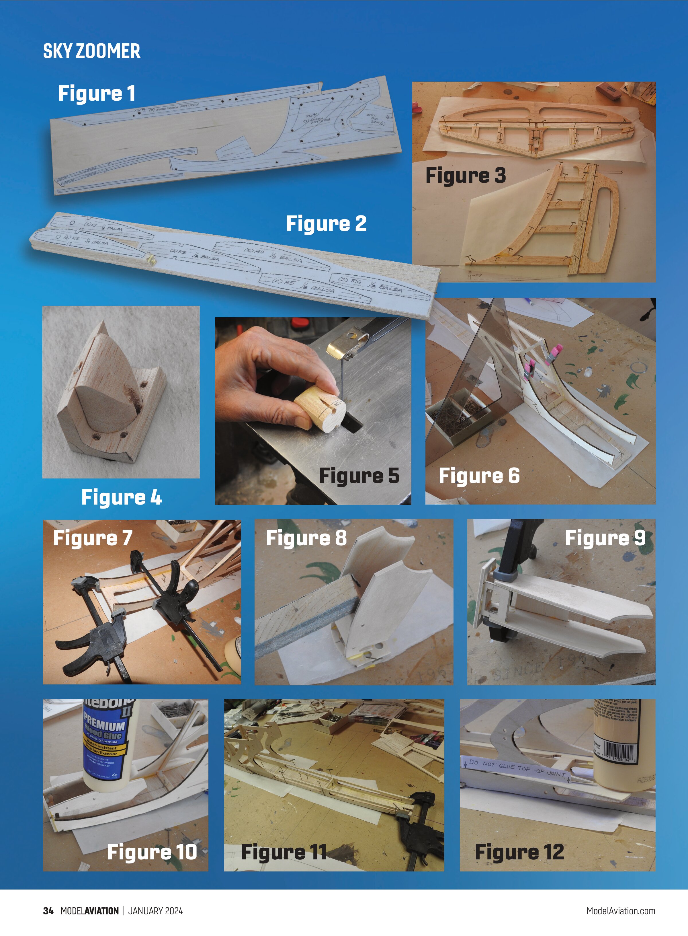
As shown in Figure 1, I have laid out all of the 1/8-inch plywood parts that need to be doubled on a 6 x 24 piece of plywood. That is done by cutting your 12 x 24 piece exactly in half the long way. You’ll notice that there is quite a bit of plywood left over in the middle; that will be used later when cutting out the formers and other parts where only one part is needed.
When cutting out the wing ribs, as shown in Figure 2, you will notice that there are many that are doubled, or, in the case of R3, six are needed, so stack the 3/32-inch balsa as thick as needed to cut out all of each rib type at the same time.
Vertical and Horizontal Stabilizer
In Figure 3, the stabilizers are shown pinned to my building board (which is a piece of drywall). Remove them and sand the edges to a nice radius. Notice that space has been allowed in the vertical stabilizer for the servo mounting.
The horizontal stabilizer has a rectangular hole in the center for the servo. You will need to make a groove in the front of the vertical stabilizer for the servo wires to go down to the hold in the top of the fuselage. At this point, it would also be great to make the slits and test-mount the five nylon hinges for the control surfaces. They will be epoxied in later.
Building the Fuselage
In Figure 4, start with the nose of the fuselage. Drill and cut it out according to the notes on the plans. It is important to note that the center of the nose is cut out because I have designed a bit of a shock absorber into the design so that the center can be pushed in to absorb some of the energy in case of a front impact.
Figure 5 shows the nose piece center being cut 1/4 inch. This space will be replaced with shock-absorbing foam later.
Figure 6 shows the fuselage sides being glued to part of the floorboard. The F2 former is glued in place using the tabs and holes. Make sure to use a square as shown so that the sides are perpendicular to the floorboard. Only apply glue from the notched part of the floorboard up to F2. I drew a 28-inch long black line on my drawing board. This is a good way to keep the center of the fuselage straight because you can keep the floorboard centered on the line as you build.
Figure 7 shows the front of the floorboard being glued to the front of the fuselage sides. The front of the floorboard should be flush with the front of F1, and the clamps should be at least the width of the fuselage.
Figure 8 shows the battery box sides being glued to F1. The top of the battery box sides should be flush with the top of F1. Before doing this, however, the battery box sides should be held the proper distance apart by tack-gluing the AA battery mount inside. It will be removed later when you are wiring the lights.
Figure 9 shows the light-switch mount being glued to F1 and to the bottom of the battery box sides. It should be flush with the bottom of those sides.
Figure 10 shows the battery box, with F1 being glued to the floorboard. I used a weight to make sure it stayed in position during drying.
Figure 11 shows the rear fuselage sides being glued to the rear floorboard. Again, make sure the centerline matches up as you glue this. Also note that the rear floorboard slants upward for the last 4 inches.
Figure 12 shows the rear window deck being glued in position. Glue to the bottom rear fuselage only. The upper part of the fuselage will later be bent over closer to the centerline.
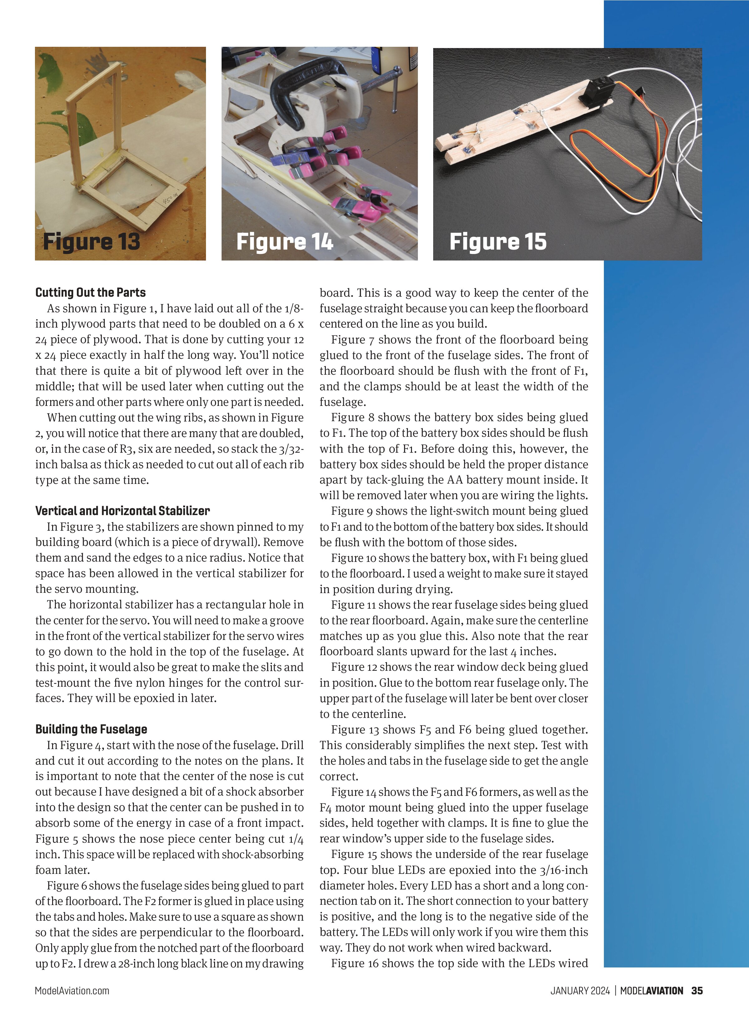
Figure 13 shows F5 and F6 being glued together. This considerably simplifies the next step. Test with the holes and tabs in the fuselage side to get the angle correct.
Figure 14 shows the F5 and F6 formers, as well as the F4 motor mount being glued into the upper fuselage sides, held together with clamps. It is fine to glue the rear window’s upper side to the fuselage sides.
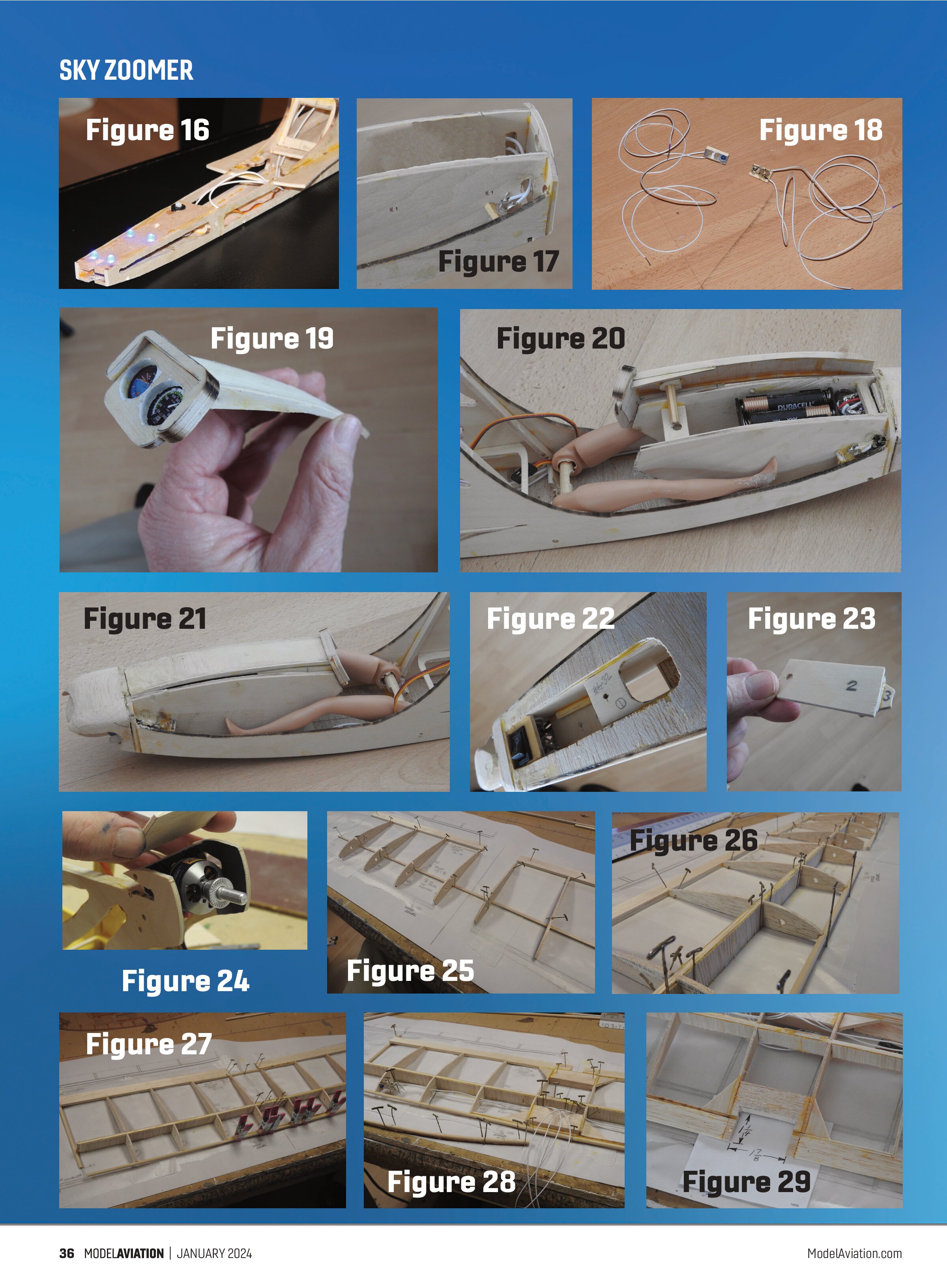
Figure 15 shows the underside of the rear fuselage top. Four blue LEDs are epoxied into the 3/16-inch diameter holes. Every LED has a short and a long connection tab on it. The short connection to your battery is positive, and the long is to the negative side of the battery. The LEDs will only work if you wire them this way. They do not work when wired backward.
Figure 16 shows the top side with the LEDs wired