Building the Wing
Figure 25 shows the plans laid out on the building table, with a sheet of waxed paper covering it. First, lay down the 1/8 x 1/8-inch square balsa strip and pin it to the table. It goes from R3 to R3 on both sides of the wing. Make sure you do this as one continuous strip, not cutting it at the wing center.
Now pin down the 3/4-inch trailing edge (TE) to the plans, as shown, from R1 to R3. This will be done in two strips, one for the right wing half and one for the left wing half. Glue all of the R2 ribs to the TE and the square strip that was pinned down earlier. Glue the R1 rib to the square strip as shown. Note that it does not touch the TE. This is for the dihedral joiner that will be put in later. Let this assembly dry.
Figure 26 shows the wing’s LE, which is the 3/16-inch dowel that is glued to the front of the R2 ribs. Note that the LE is elevated roughly 3/32 inch above your building board. It should be cut to length, as shown on the plans.
Glue in the top part of the wing spar, which is a 1/8 x 1/8-inch balsa strip. This should be cut at the middle of the wing so that there is a 1/16-inch gap right in the center of the wing. Glue on all of the webbing that will finish the wing spar on both sides. This is 1/16- or 1/32-inch (optional) thick balsa and there will be 16 pieces glued, which are 2-7/8 x 3/4-inch balsa pieces. Do not glue the web pieces in the center between the wing halves at this time.
Figure 27 shows the dihedral joiners added at both the front and rear center sections of the wing. The 1/16-inch balsa webbing has been glued to the spar on both front and rear of the square balsa strips. The correct dihedral is held by laying a 3/16-inch dowel under the wing at the R3 location on both wing halves.
Figure 28 has a lot going on. In the front of the photo, you can see what will be the LE of the curved part of the outside of the wing. The 3/16-inch dowel has quite a lot of curvature. I submerged a dowel in water for approximately 4 hours so that it would be soft enough to bend.
I laid the wet dowel on top of the 1/8-inch plywood front wing doubler and pinned it to force it into the correct curvature, letting it dry overnight. I then glued it to the 1/8-inch front wing doubler. It was pinned again to hold the curve.
Follow this same procedure for the TE, again first soaking the balsa for 4 hours. Make sure that you make right and left parts when doing this. I have also installed the LED lights that were soldered together and mounted on the 1/8-inch plywood piece. Install them in the location on the drawing and make sure that the light mount is flush with the top of the wing rib. At the wing’s center, the balsa block front and rear wing mounts are glued in place and four of the 3/16-inch wing gussets are added.
Figure 29 shows that the center rear portion of the wing has been cut out. Cut it as shown at 1-1/4-inch


At a Glance
Specifications
Wingspan: 48 inches
Length: 35 inches
Weight: 1 pound, 8 ounces with battery
Test-Model Details
Motor used: E-flite 370, 1,080 Kv or equivalent
ESC: E-flite 30-amp
Battery: 3S LiPo 450 mAh
Servos: Two Hitec HS-55
Propeller: 7 x 5 electric
deep and 1-7/8-inch wide. Make sure this cutout is exactly centered.
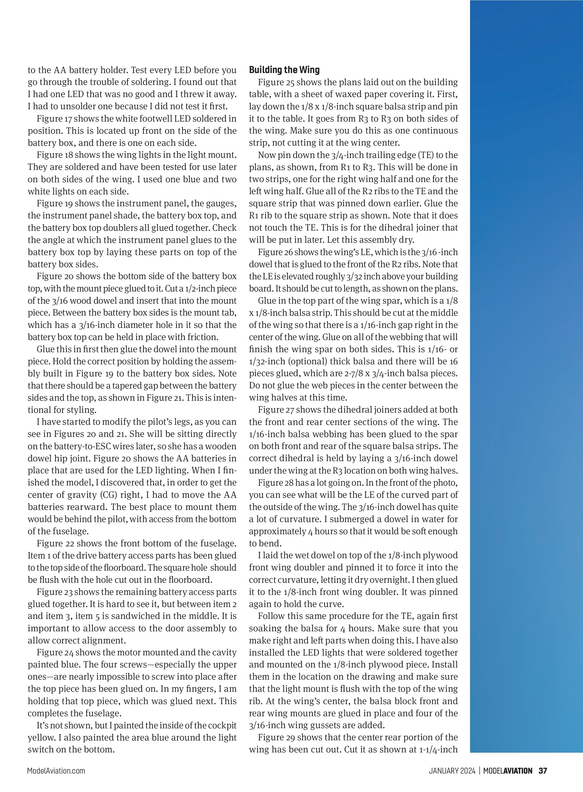
Figure 30 shows an old VHS tape laying over the plans on top of the R6 rib. A VHS tape is exactly 1 inch wide, so if you don’t have one, use a block that is straight and 1 inch thick. The curved LE you made earlier is laid flush with the 1-inch spacer but with a 3/32-inch spacer under it. Where the curved LE meets R3, there should also be a 3/32-inch spacer under it. On the backside, the curved TE should be laid against the LE at R3. R3 is glued in at the same time as R6, which connects the front and rear curved edges.
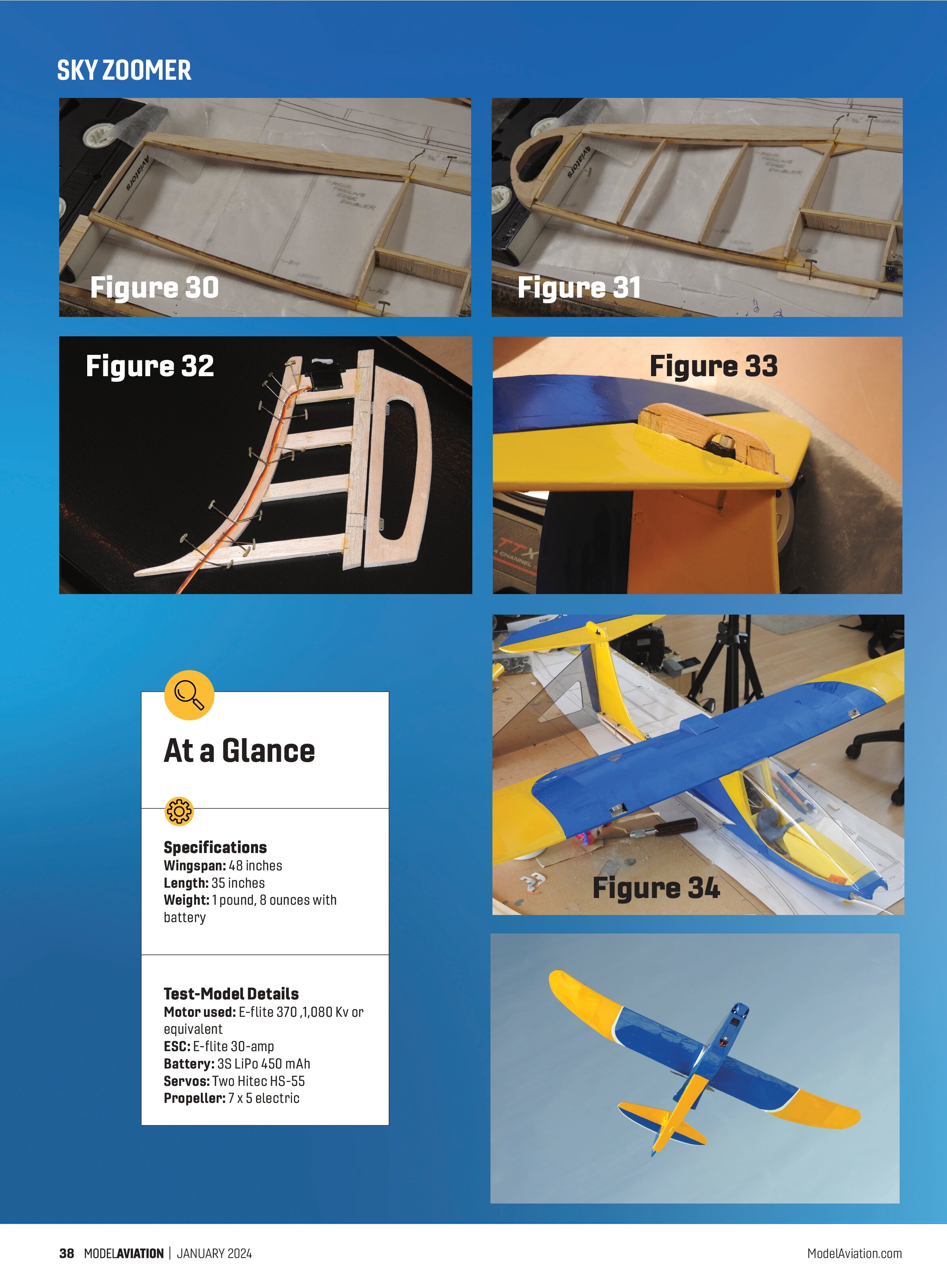
Figure 31 shows the remaining pieces of the wing being added. Let this assembly dry completely. Unpin the wing and repeat the last two steps for the other side of the wing.
Final Assembly and Covering
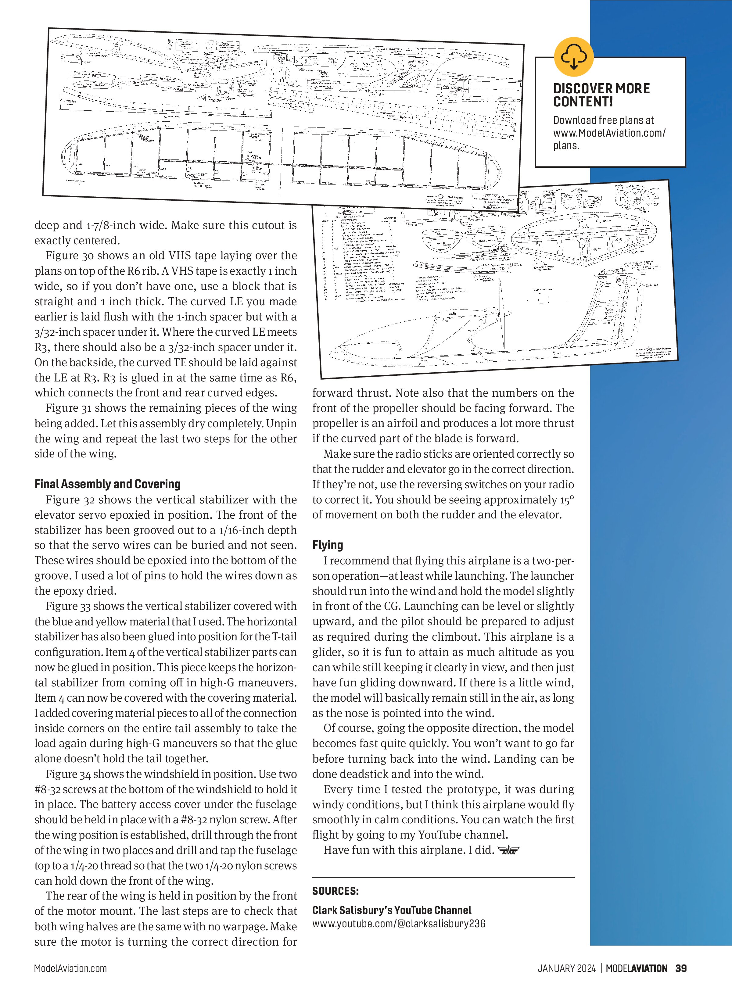
Figure 32 shows the vertical stabilizer with the elevator servo epoxied in position. The front of the stabilizer has been grooved out to a 1/16-inch depth so that the servo wires can be buried and not seen. These wires should be epoxied into the bottom of the groove. I used a lot of pins to hold the wires down as the epoxy dried.
Figure 33 shows the vertical stabilizer covered with the blue and yellow material that I used. The horizontal stabilizer has also been glued into position for the T-tail configuration. Item 4 of the vertical stabilizer parts can now be glued in position. This piece keeps the horizontal stabilizer from coming off in high-G maneuvers. Item 4 can now be covered with the covering material. I added covering material pieces to all of the connection inside corners on the entire tail assembly to take the load again during high-G maneuvers so that the glue alone doesn’t hold the tail together.
Figure 34 shows the windshield in position. Use two #8-32 screws at the bottom of the windshield to hold it in place. The battery access cover under the fuselage should be held in place with a #8-32 nylon screw. After the wing position is established, drill through the front of the wing in two places and drill and tap the fuselage top to a 1/4-20 thread so that the two 1/4-20 nylon screws can hold down the front of the wing.
The rear of the wing is held in position by the front of the motor mount. The last steps are to check that both wing halves are the same with no warpage. Make sure the motor is turning the correct direction for forward thrust. Note also that the numbers on the front of the propeller should be facing forward. The propeller is an airfoil and produces a lot more thrust if the curved part of the blade is forward.
Make sure the radio sticks are oriented correctly so that the rudder and elevator go in the correct direction. If they’re not, use the reversing switches on your radio to correct it. You should be seeing approximately 15° of movement on both the rudder and the elevator.
Flying
I recommend that flying this airplane is a two-person operation—at least while launching. The launcher should run into the wind and hold the model slightly in front of the CG. Launching can be level or slightly upward, and the pilot should be prepared to adjust as required during the climbout. This airplane is a glider, so it is fun to attain as much altitude as you can while still keeping it clearly in view, and then just have fun gliding downward. If there is a little wind, the model will basically remain still in the air, as long as the nose is pointed into the wind.
Of course, going the opposite direction, the model becomes fast quite quickly. You won’t want to go far before turning back into the wind. Landing can be done deadstick and into the wind.
Every time I tested the prototype, it was during windy conditions, but I think this airplane would fly smoothly in calm conditions. You can watch the first flight by going to my YouTube channel.
Have fun with this airplane. I did.
SOURCES:
Clark Salisbury’s YouTube Channel
www.youtube.com/@clarksalisbury236