RC SCALE AEROBATICS

EXECUTING A DOWN SHARK’S TOOTH MANEUVER
By John Glezellis | jglezellis@gmail.com
AS COMPETITORS BEGIN to look at the various International Miniature Aerobatic Club (IMAC) Known, as well as any practice Unknown schedule, they will notice that similar maneuvers exist in their most basic form but can contain many different individual elements that contribute to general complexity.
In the 2023 Basic class, a 1-1/2-turn upright spin is found, where in the 2023 Unlimited program, a Down Shark’s Tooth maneuver consists of a 1-3/4-turn upright spin as just a single item. This maneuver also contains an opposite-direction 3/4 roll after the spin is complete and a push to a 45° upline with a half roll, followed by an opposite two points of a four-point roll and a push to an upright exit.
Throughout the course of this column, I will examine a few key items pertaining to the execution of the Down Shark’s Tooth from not only a flight perspective but also both the setup of the radio and engine to result in consistent performance, all while also trying to decrease the workload of the pilot. Without further delay, let’s begin!
Maneuver Complexity
The aerobatic competitor must not only think about flying the perfect maneuver but they also must think about planning it so that the exit of one figure properly positions the aircraft for the next in altitude, attitude, heading (if it’s a cross-box figure), and spacing. I would recommend flipping to the flight mode (or rate settings) that is used for spins a few seconds before you begin decreasing the airspeed.
The entry-line segment is to be judged and downgraded as required, in the same manner as any other wind-corrected horizontal line. For the spin, judges look to see that the airplane performed a clean break and a fully stalled autorotation, that it stopped on a prestated heading, and that a 90° downline was performed.
After the rotation is complete, change to the lower rate flight mode and perform the 3/4 roll at a constant rotation rate, with a brief line segment being shown between the spin rotation and the rolling element. The rotation speed and pitch attitude during the autorotation, however, are not downgrades because all models spin differently. Should you only use aileron to complete the spin, a penalty of one point per 5° will apply.
Now that the spin and rolling element are complete for the figure, push to a 45° upline and perform a half roll, followed by an opposite two points of a four-point roll. These rolling items are to be centered within the upline segment and the pilot will push to an upright, level exit. Radii do not need to match between each corner of the figure. The initial horizontal line and the line at the end of the figure can be flown at different altitudes.
Earlier, I mentioned the use of flight modes and rates. With this maneuver being fairly complex, let’s now transition into how you can utilize certain features from most of today’s radio offerings.
Switch Simplicity and Mechanical Basics
With various elements found in the Down Shark’s Tooth, my recommendation is to perform this figure using two different flight modes located on either a two- or three-position switch. If you have been an avid reader of my columns, I am sure that you are aware that I use three flight modes on all of my aerobatic models.
Using the Spektrum iX20 as an example, and because I am a “thumb” flier, I use Switch G to control my flight modes because my index finger is naturally positioned near this switch. On this switch, one position is for precision flight and Hammerheads (Position 2), another for snap rolls and spins (Position 1), and the last position (Position 0) is for either 3D maneuvers or tailslides, where a lot of elevator deflection is needed.
Regarding elevator deflection for the spin rate, ensure that the aircraft can stall consistently. Should a break for the spin be rather difficult to achieve, examine different center-of-gravity positions.
Throughout the years, I have found that it might be necessary to utilize different exponential settings of up and down deflection for the elevator to result in a similar feel from the aircraft. I urge you to try different settings in small increments and note the result. Nonetheless, besides thinking of flight modes for only control-surface deflection, also use them for programmable mixes and/or different throttle curves.
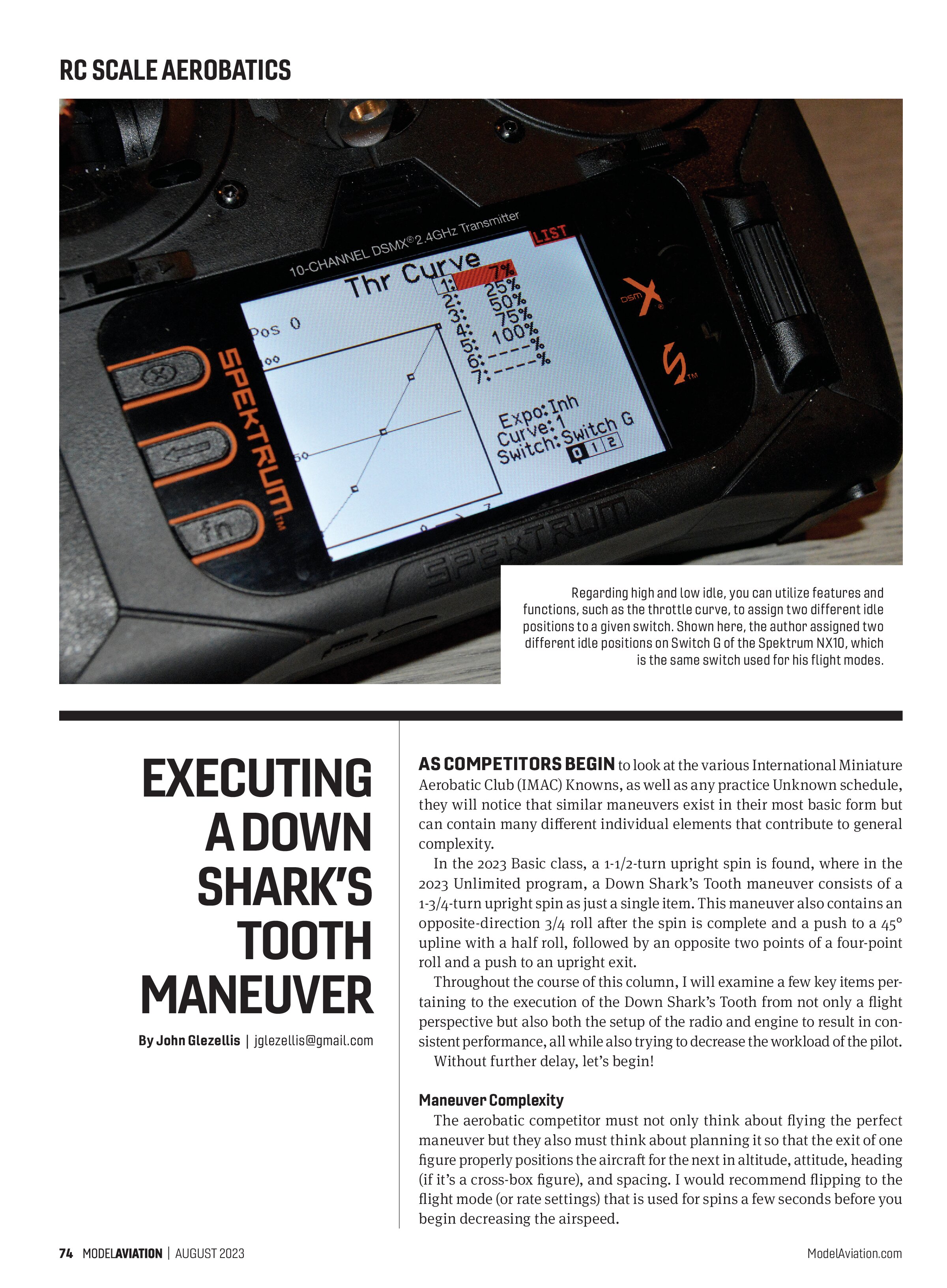
For maneuvers such as spins, stall turns, and tailslides, a higher throttle setting for the idle position is beneficial to prevent a flameout from occurring. Some pilots prefer to use two different idle settings, where a higher idle value is found for normal flight and a lower idle is found on another position.


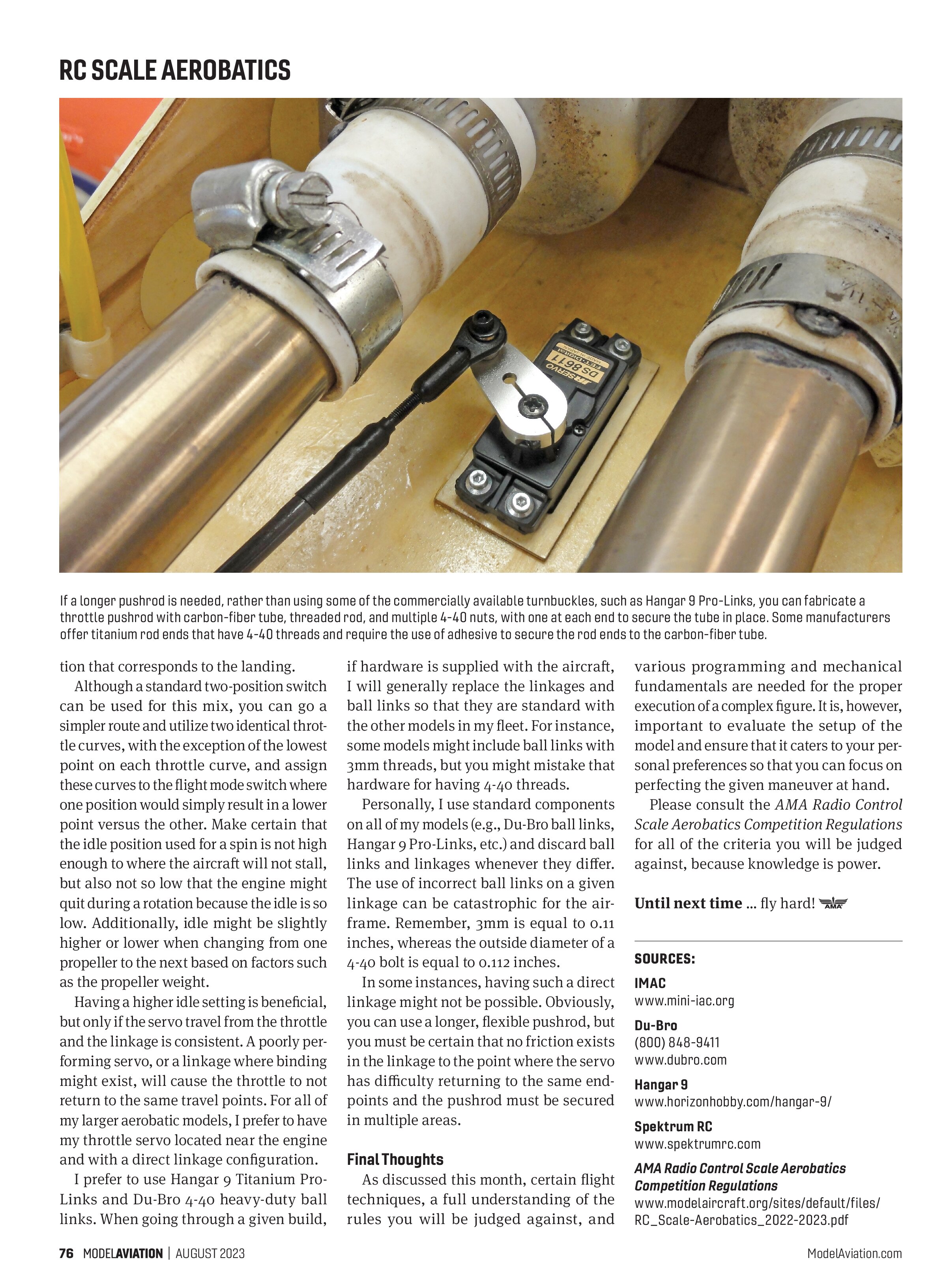
If a longer pushrod is needed, rather than using some of the commercially available turnbuckles, such as Hangar 9 Pro-Links, you can fabricate a throttle pushrod with carbon-fiber tube, threaded rod, and multiple 4-40 nuts, with one at each end to secure the tube in place. Some manufacturers offer titanium rod ends that have 4-40 threads and require the use of adhesive to secure the rod ends to the carbon-fiber tube.
tion that corresponds to the landing.
Although a standard two-position switch can be used for this mix, you can go a simpler route and utilize two identical throttle curves, with the exception of the lowest point on each throttle curve, and assign these curves to the flight mode switch where one position would simply result in a lower point versus the other. Make certain that the idle position used for a spin is not high enough to where the aircraft will not stall, but also not so low that the engine might quit during a rotation because the idle is so low. Additionally, idle might be slightly higher or lower when changing from one propeller to the next based on factors such as the propeller weight.
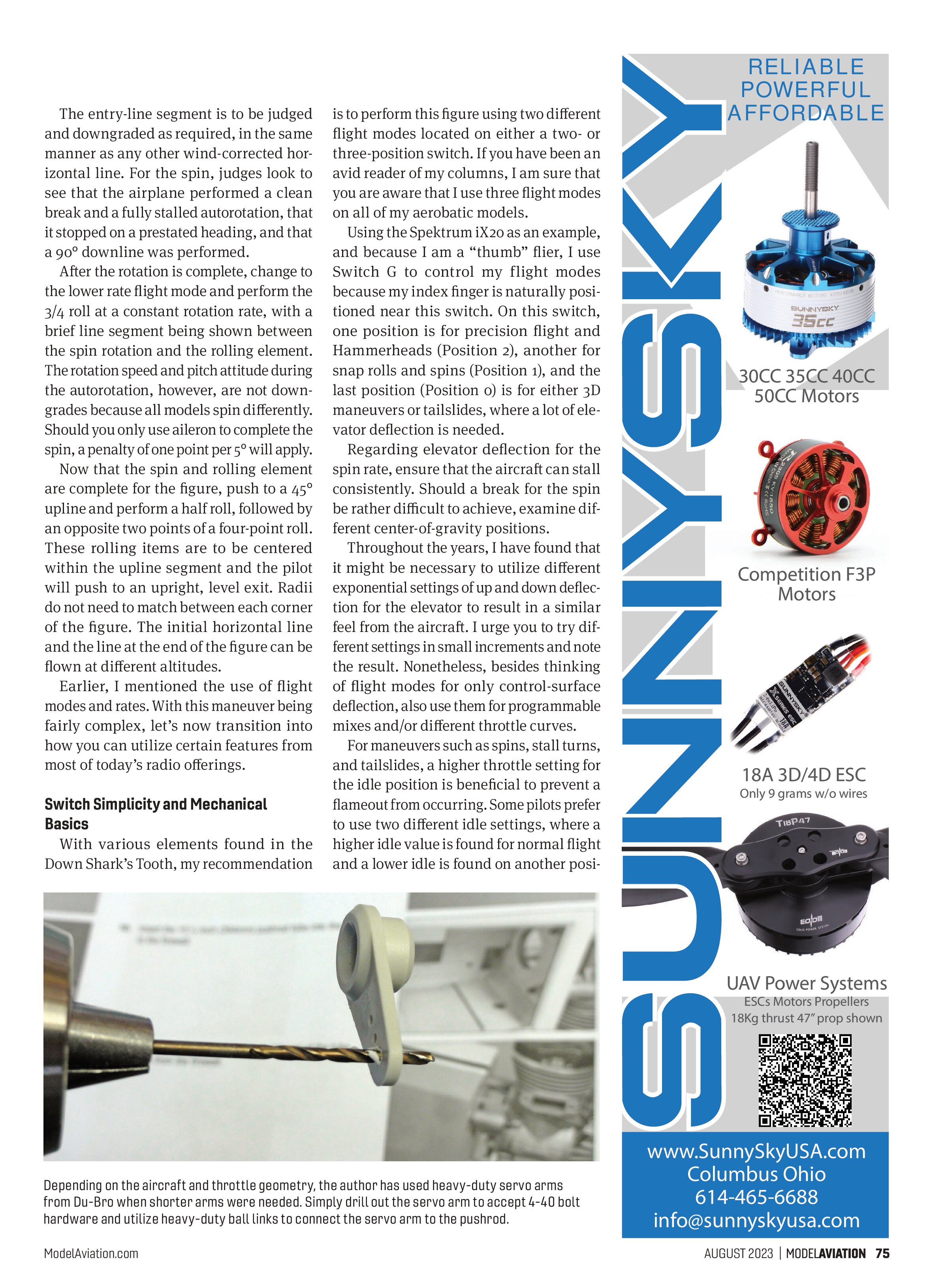
Having a higher idle setting is beneficial, but only if the servo travel from the throttle and the linkage is consistent. A poorly performing servo, or a linkage where binding might exist, will cause the throttle to not return to the same travel points. For all of my larger aerobatic models, I prefer to have my throttle servo located near the engine and with a direct linkage configuration.
I prefer to use Hangar 9 Titanium Pro-Links and Du-Bro 4-40 heavy-duty ball links. When going through a given build,
if hardware is supplied with the aircraft, I will generally replace the linkages and ball links so that they are standard with the other models in my fleet. For instance, some models might include ball links with 3mm threads, but you might mistake that hardware for having 4-40 threads.
Personally, I use standard components on all of my models (e.g., Du-Bro ball links, Hangar 9 Pro-Links, etc.) and discard ball links and linkages whenever they differ. The use of incorrect ball links on a given linkage can be catastrophic for the airframe. Remember, 3mm is equal to 0.11 inches, whereas the outside diameter of a 4-40 bolt is equal to 0.112 inches.
In some instances, having such a direct linkage might not be possible. Obviously, you can use a longer, flexible pushrod, but you must be certain that no friction exists in the linkage to the point where the servo has difficulty returning to the same end-points and the pushrod must be secured in multiple areas.
Final Thoughts
As discussed this month, certain flight techniques, a full understanding of the rules you will be judged against, and various programming and mechanical fundamentals are needed for the proper execution of a complex figure. It is, however, important to evaluate the setup of the model and ensure that it caters to your personal preferences so that you can focus on perfecting the given maneuver at hand.
Please consult the AMA Radio Control Scale Aerobatics Competition Regulations for all of the criteria you will be judged against, because knowledge is power.
Until next time ... fly hard!
SOURCES:
IMAC
www.mini-iac.org
Du-Bro
(800) 848-9411
www.dubro.com
Hangar 9
www.horizonhobby.com/hangar-9/
Spektrum RC
www.spektrumrc.com
AMA Radio Control Scale Aerobatics Competition Regulations
www.modelaircraft.org/sites/default/files/RC_Scale-Aerobatics_2022-2023.pdf