
RC JETS
MAKING A NEW NOSE-GEAR DOOR
By Jim Hiller | jetmodeler@earthlink.net

WELL, I DID it again. I lost the nose-gear door on my Xtreme ARF Vixen sport jet. It blew off in flight on a high-speed, knife-edge pass when the air loads pulled it open. It was time to make a new door.
The Vixen has been out of production for some time now, so a replacement door from the factory was out of the question. I chose to make the replacement door from fiberglass. It was a simple and quick process to learn how to work with fiberglass and molds. I had two options for making a mold—a female mold or a simple male mold. In this case, I went with a simple male mold because I could use the airframe as the mold.
I wrapped the area where the nose-gear door had been with a piece of .020-inch thick plastic that was secured with packing tape, thus giving me the shape again. Packing tape is an excellent way to protect the painted surface, and the tape itself extended several inches beyond the gear door requirements. Approximately eight coats of release wax were used on the plastic and tape—even the painted area of the nose section of the model was waxed to make the part release reliably.
The next big question was how much fiberglass cloth to use. I prefer thick, stiff gear doors, so I chose approximately 30 to 35 ounces of cloth. This was done by using six layers of 6-ounce-per-square-yard standard cloth, followed by a 2-ounce layer of tight-weave cloth on the outer surface. The lighter and finer weave reduced the fill requirements to obtain a quality finish.
The fiberglass cloth was then cut approximately 3/4 inch oversize to the door opening to leave plenty of extra cloth with which to work. Use care not to distort the weave of the cloth as you handle it or you will lose the nice rectangle shape.
West System 105 Epoxy Resin with 205 Fast Hardener was my epoxy of choice. I have had good experiences with these products. I started by laying down my first layer of 6-ounce cloth, carefully centering it over the opening for the gear door then wetting it out. Use great care not to spill epoxy beyond the taped area because cleaning up painted surfaces is not desirable.
The remaining layers of 6-ounce cloth were then laid and wetted out. Take time with each layer to fully saturate the cloth with the epoxy from the previous layer. You do not want any dry fiberglass. The final layer of 2-ounce fiberglass cloth is to reduce the material required for a smooth finish.
The layup was allowed to partially cure to a semisoft condition before the final finish was applied. My finish of choice was again West System 105 and 205, but this time joined with the West System 497 Low-Density Fairing microballoons filler, mixed to the consistency of peanut butter. This is an efficient and easily sanded method to quickly fill the weave.
After the nose gear fully cured, it was sanded to a smooth finish while still on the fuselage mold. It took a second coat of the microballoons and epoxy mix, followed by block sanding, to get a good, flat part.
Sanding started at this point with 80-grit sandpaper and ended with a final sanding of 220-grit sandpaper to remove the heavy sanding marks. The part was removed from the fuselage mold. If release is a problem, remove the tape and plastic mold from the model then pull the tape and plastic from the fiberglass part.
The new gear door was then trimmed to fit prior to the final finish and paint; in this case, with simple spray can primer and paints. I found some paints that closely matched the Vixen’s colors. This time, I mounted the nose-gear door with a stiffer, stronger pushrod—the root cause of the failure that resulted in the original nose-gear door failure.
CST The Composites Store is a good supplier of products for a simple job such as this. I use the company as a one-stop shop for my fiberglass and epoxy needs. It has a good selection of West System products and fiberglass cloth for our modeling needs. Check out CST when your needs arise. The website is listed in “Sources.”
Picaro Winter Build
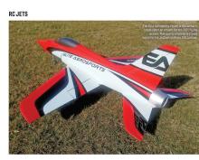
My winter build—or really just assembly—was an Elite Aerosports Picaro, a rather large, aerobatic sport jet. I had an opportunity to fly one a while back and really liked the way it flew and looked.
I ordered the Picaro with a select paint scheme while at Jets Over Kentucky, with the knowledge that it would take approximately six months to arrive. That was about right because I received the airframe as a nice, late Christmas present. The box was well packaged, with the airframe undamaged and ready for the start of the build.
The Picaro is a large model with a 108-inch fuselage, 88-inch wingspan, and an expected weight in the low 40-pound range. It’s a nice-size model. The supplied landing gear is an Electron Retracts ER-50 system with an Electron GS-200 controller. This is a nice, top-of-the-line, rugged landing gear system.


I found the Picaro to have a high-quality, painted, out-of-the-mold finish that was well done. All of the formers and the structure are plywood covered, with a thin layer of carbon fiber on both sides, which offers a good, lightweight, and stiff result.
The system’s layout is easily accessible for ease of build and maintenance, and it’s a well-thought-out design by the people who fly what they sell. I am looking forward to the test flight when the weather allows.
Setting the Tailpipe Position
A quick word for newcomers about how to set the tailpipe position in jets. The concept of a turbine tailpipe is based on pulling air around the tailpipe between the inner and outer layers.
This is done by inserting the inner tailpipe approximately 1/4 to 1/2 inch from the lip of the outer layer. This inset gap allows the low-pressure, high-velocity turbine exhaust to suck air from the front of the gap between the two layers, providing a cool layer of air to the outer surface.
This concept is also applied to setting the tailpipe to the fuselage. Set the outer layer of the tailpipe approximately 1/4 to 1/2 inch in from the fuselage to allow the same process of air flow between the outer layer of the tailpipe and the fuselage. This method has proven to be a reliable and effective way to keep the aft fuselage temperatures cooler.
After the tailpipe is positioned from the back side, the turbine can then be located to the tailpipe bell mouth. Follow the manufacturer’s recommendations found in the turbine manual.
The dimension is measured from the start of the minimum diameter of the bell mouth to the turbine’s exhaust opening. The length of this gap is dependent on the turbine’s thrust.
It is important to suck in cool air through the bell mouth into the tailpipe.
SOURCES:
Jet Pilots Organization (JPO)
www.jetpilots.org
West System
(866) 937-8797
www.westsystem.com
CST The Composites Store
(661) 822-4162
www.cstsales.com
Elite Aerosports
(954) 444-8809
www.eliteaerosports.com
Electron Retracts
(765) 744-3118
www.jag-rc.com
www.electron-retracts.com

