TESTING AND ADJUSTING THE ENGINE THRUST ANGLE
RC SCALE AEROBATICS
By John Glezellis | jglezellis@gmail.com

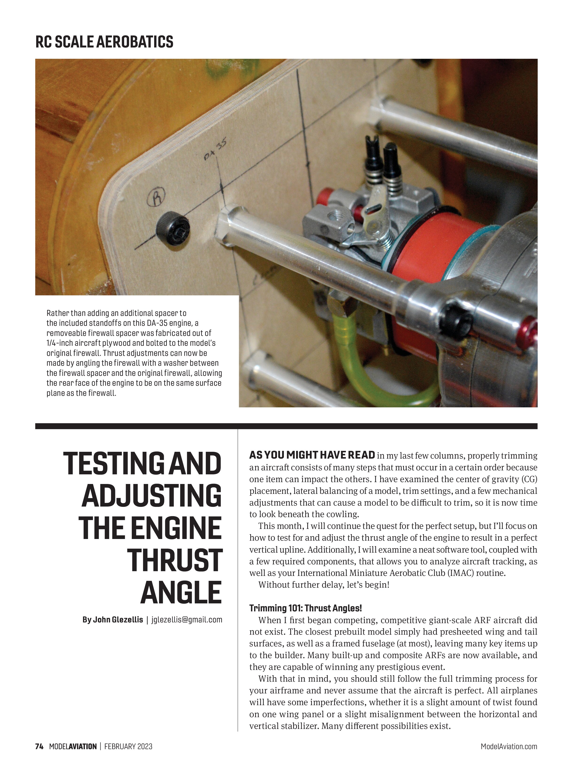
AS YOU MIGHT HAVE READ in my last few columns, properly trimming an aircraft consists of many steps that must occur in a certain order because one item can impact the others. I have examined the center of gravity (CG) placement, lateral balancing of a model, trim settings, and a few mechanical adjustments that can cause a model to be difficult to trim, so it is now time to look beneath the cowling.
This month, I will continue the quest for the perfect setup, but I’ll focus on how to test for and adjust the thrust angle of the engine to result in a perfect vertical upline. Additionally, I will examine a neat software tool, coupled with a few required components, that allows you to analyze aircraft tracking, as well as your International Miniature Aerobatic Club (IMAC) routine.
Without further delay, let’s begin!
Trimming 101: Thrust Angles!
When I first began competing, competitive giant-scale ARF aircraft did not exist. The closest prebuilt model simply had presheeted wing and tail surfaces, as well as a framed fuselage (at most), leaving many key items up to the builder. Many built-up and composite ARFs are now available, and they are capable of winning any prestigious event.
With that in mind, you should still follow the full trimming process for your airframe and never assume that the aircraft is perfect. All airplanes will have some imperfections, whether it is a slight amount of twist found on one wing panel or a slight misalignment between the horizontal and vertical stabilizer. Many different possibilities exist.

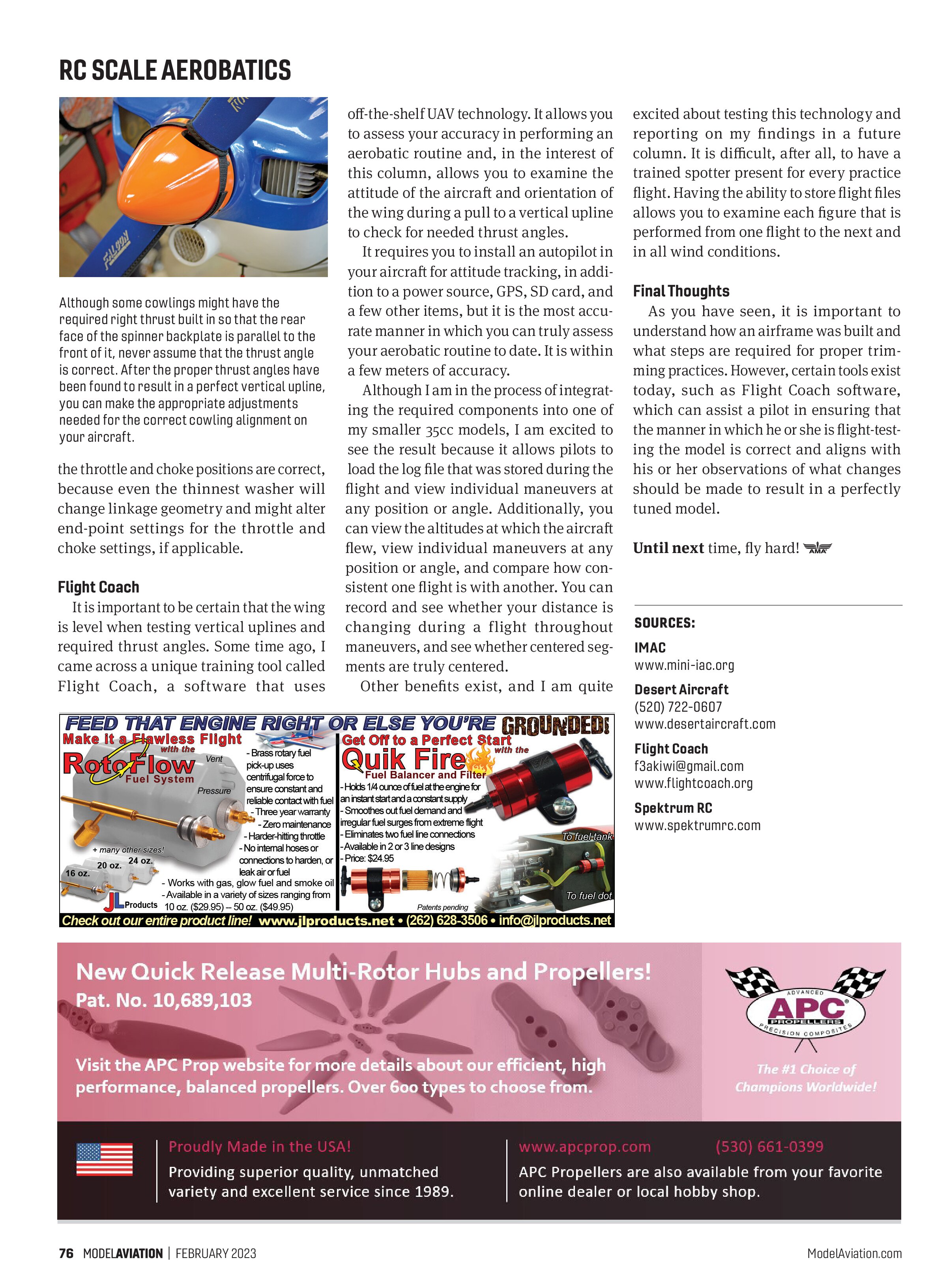
Although some cowlings might have the required right thrust built in so that the rear face of the spinner backplate is parallel to the front of it, never assume that the thrust angle is correct. After the proper thrust angles have been found to result in a perfect vertical upline, you can make the appropriate adjustments needed for the correct cowling alignment on your aircraft.
the throttle and choke positions are correct, because even the thinnest washer will change linkage geometry and might alter end-point settings for the throttle and choke settings, if applicable.
Flight Coach
It is important to be certain that the wing is level when testing vertical uplines and required thrust angles. Some time ago, I came across a unique training tool called Flight Coach, a software that uses off-the-shelf UAV technology. It allows you to assess your accuracy in performing an aerobatic routine and, in the interest of this column, allows you to examine the attitude of the aircraft and orientation of the wing during a pull to a vertical upline to check for needed thrust angles.
It requires you to install an autopilot in your aircraft for attitude tracking, in addition to a power source, GPS, SD card, and a few other items, but it is the most accurate manner in which you can truly assess your aerobatic routine to date. It is within a few meters of accuracy.
Although I am in the process of integrating the required components into one of my smaller 35cc models, I am excited to see the result because it allows pilots to load the log file that was stored during the flight and view individual maneuvers at any position or angle. Additionally, you can view the altitudes at which the aircraft flew, view individual maneuvers at any position or angle, and compare how consistent one flight is with another. You can record and see whether your distance is changing during a flight throughout maneuvers, and see whether centered segments are truly centered.
Other benefits exist, and I am quite excited about testing this technology and reporting on my findings in a future column. It is difficult, after all, to have a trained spotter present for every practice flight. Having the ability to store flight files allows you to examine each figure that is performed from one flight to the next and in all wind conditions.
Final Thoughts
As you have seen, it is important to understand how an airframe was built and what steps are required for proper trimming practices. However, certain tools exist today, such as Flight Coach software, which can assist a pilot in ensuring that the manner in which he or she is flight-testing the model is correct and aligns with his or her observations of what changes should be made to result in a perfectly tuned model.
Until next time, fly hard!
SOURCES:
IMAC
www.mini-iac.org
Desert Aircraft
(520) 722-0607
www.desertaircraft.com
Flight Coach
f3akiwi@gmail.com
www.flightcoach.org
Spektrum RC
www.spektrumrc.com