BUILDING RC COMBAT AIRPLANES WITH ALUMINUM CHANNEL
By Heath Bartel | heath.bartel@gmail.com

BUILDING COMBAT AIRPLANES from aluminum channel has a long history for good reason. Building a fuselage out of aluminum channel is one of the fastest and easiest methods by simply cutting the channel to length and drilling a few holes. Unlike 3D printing, building with aluminum channel does not require any specialized tools. A few common tools, such as a drill, hacksaw, file, and screwdriver, are all that are needed.
Aluminum channel is strong and relatively lightweight, but it is not the lightest or strongest material available. Foam is lighter and carbon fiber is both lighter and stronger, so why use aluminum channel?
Carbon fiber outperforms aluminum at resisting bending loads. However, carbon-fiber rods tend to crack lengthwise when loaded end-on. Drilling holes for attachment bolts or pins in carbon-fiber tubes makes this problem worse by creating stress points that can lead to cracking. Although drilling holes in aluminum also creates a weak point, aluminum will tend to bend or deform, not crack. In many cases, it can simply be bent back into its original shape.
Compared with aluminum, carbon fiber is also more of a hassle to cut and drill. It is generally a special-order item, while aluminum channel can be purchased at any home improvement store, often in several different lengths and widths. The final issue with carbon fiber is that it can be costly, especially if you upgrade to a wrapped carbon-fiber tube.
The primary advantages of aluminum channel over foam are greater strength and a fast, simple build. A simple foam structure without reinforcements will be lighter but much weaker. A foam composite structure with fiberglass or carbon fiber could equal or exceed the strength of aluminum, but it would be more complicated and time-consuming to build.
Aluminum channel provides a built-in slot for wires and limited space for components. If the ESC and receiver are small enough that they can be tucked into the channel, it provides excellent protection while also allowing easy access. The simple, wide-open nature of an aluminum channel allows the wing to be easily shifted a few inches to adjust the center of gravity without redesigning the fuselage.
The two most common methods of mounting a wing to an aluminum-channel airplane are wing bolts and rubber bands. Bolting the wing directly to the channel is a simple method that works best with a shorter wing that doesn’t need to be removed for transport. A good example of this technique is the classic Gnat design.
Another common method is to use rubber bands connected to pins or hooks. Using rubber bands allows the wing to shift some in an impact and also makes the wing much easier to remove for transport. This is more important for larger wings, such as the 64-inch one that is commonly used for Slow Survivable Combat (SSC).
Although aluminum-channel fuselages have many advantages, they also have two related drawbacks. Because the larger components don’t fit inside the channel, they need to be mounted externally. This leads to increased drag and does not offer protection for the externally mounted components in a collision.
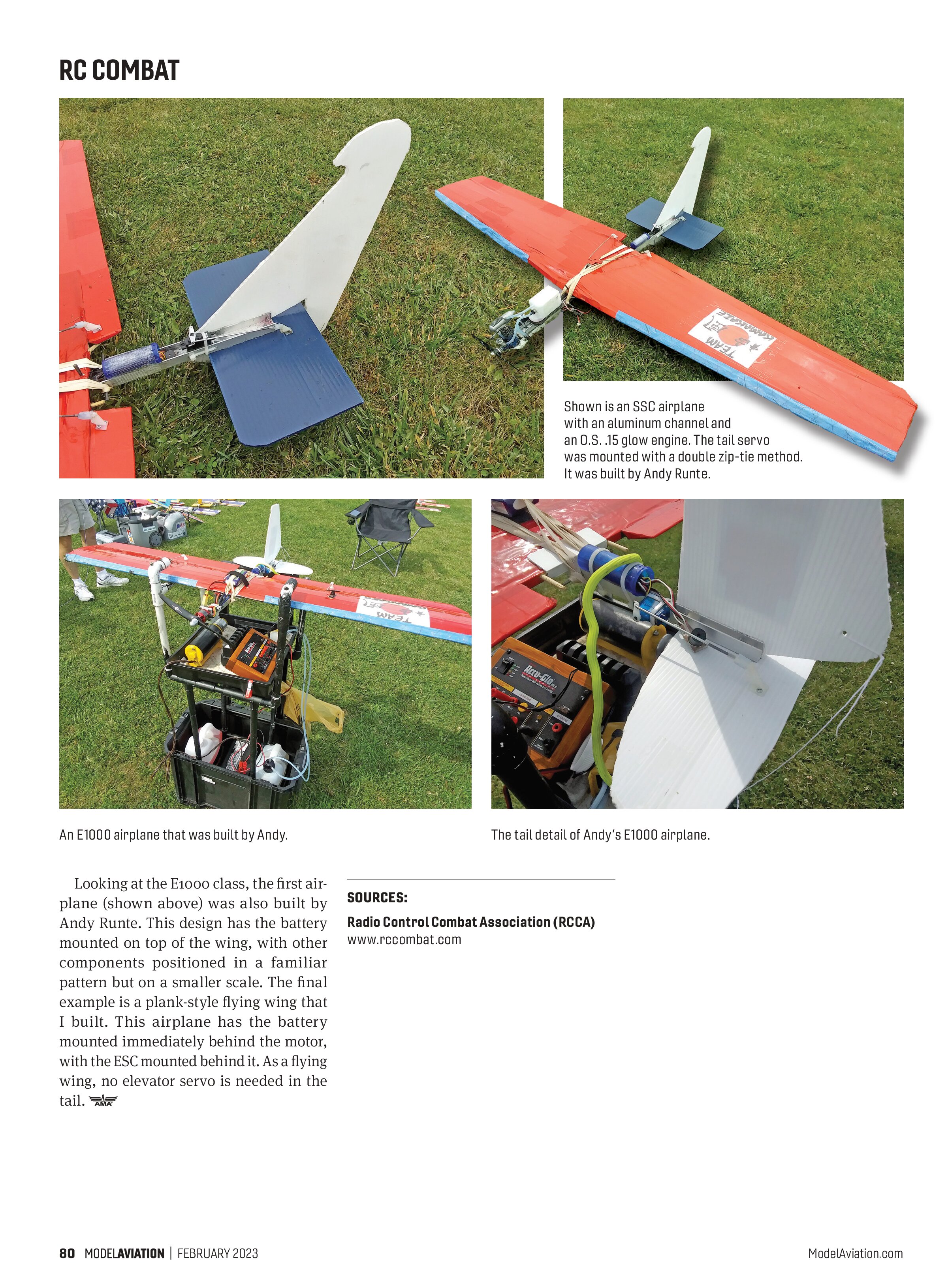
Let’s take a look at some examples of airplanes built with aluminum channel. The first is an SSC airplane built by Andy Runte. It is powered by an O.S. .15 glow engine mounted on a plastic engine mount. A throttle servo is mounted behind the engine. A fuel tank rounds out the front of the airplane. The receiver is mounted behind the wing. Note the double zip-tie technique on the elevator servo. The tail and elevator are built from 4mm Coroplast.
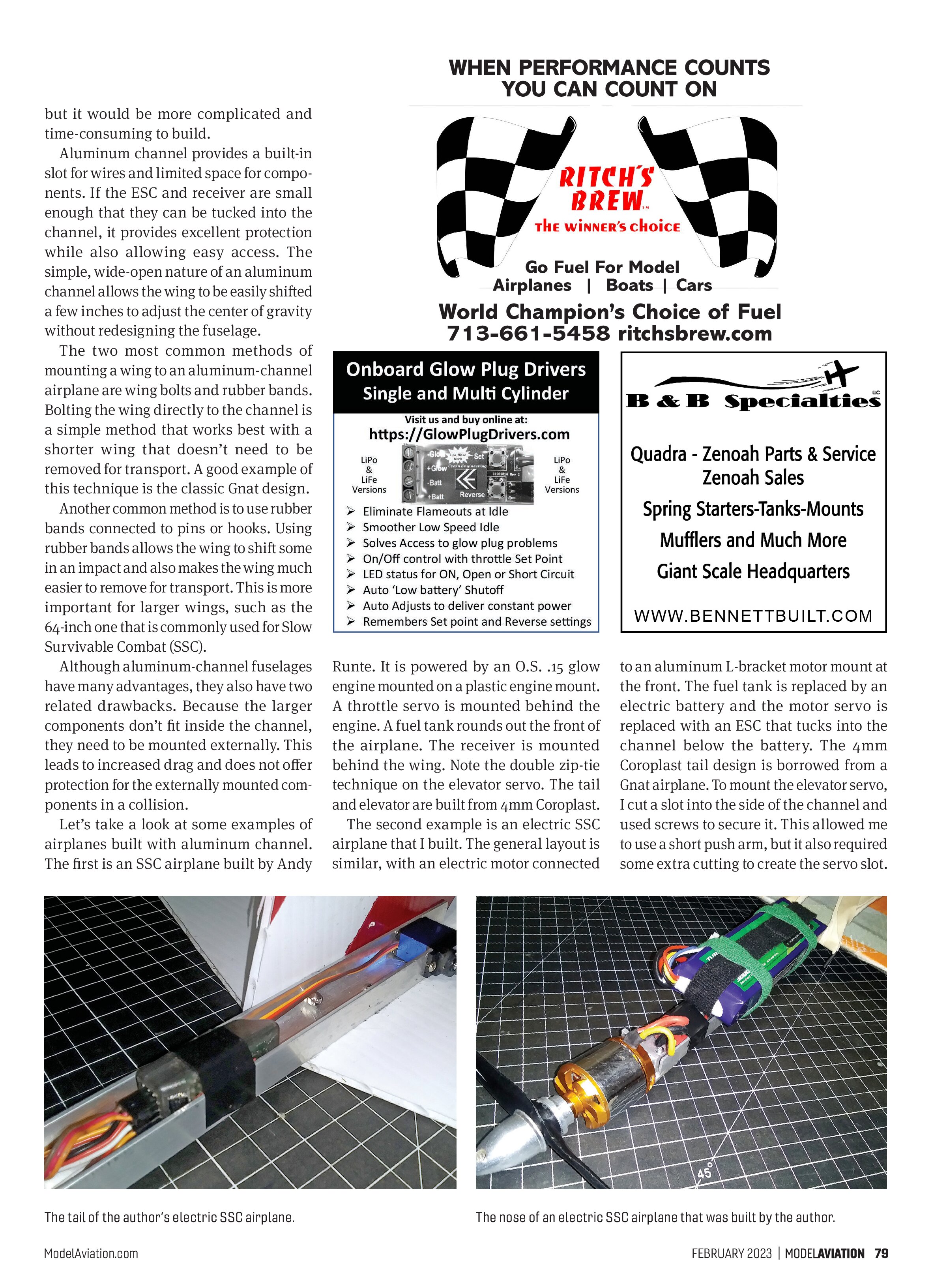
The second example is an electric SSC airplane that I built. The general layout is similar, with an electric motor connected to an aluminum L-bracket motor mount at the front. The fuel tank is replaced by an electric battery and the motor servo is replaced with an ESC that tucks into the channel below the battery. The 4mm Coroplast tail design is borrowed from a Gnat airplane. To mount the elevator servo, I cut a slot into the side of the channel and used screws to secure it. This allowed me to use a short push arm, but it also required some extra cutting to create the servo slot.


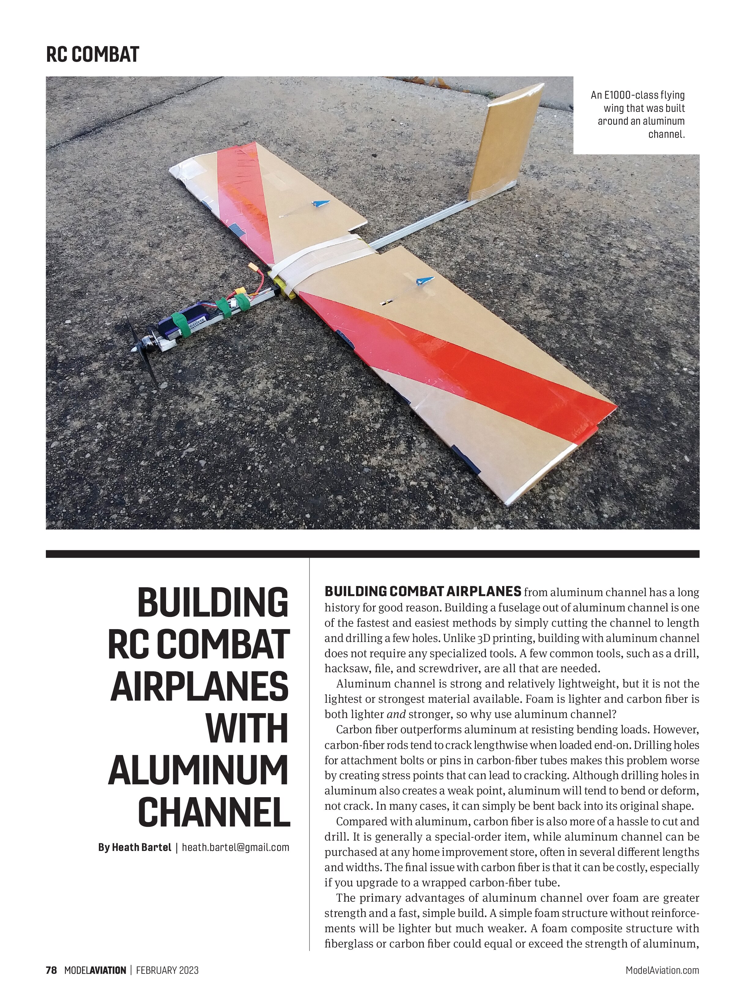
Looking at the E1000 class, the first airplane (shown above) was also built by Andy Runte. This design has the battery mounted on top of the wing, with other components positioned in a familiar pattern but on a smaller scale. The final example is a plank-style flying wing that I built. This airplane has the battery mounted immediately behind the motor, with the ESC mounted behind it. As a flying wing, no elevator servo is needed in the tail.
SOURCES:
Radio Control Combat Association (RCCA)
www.rccombat.com