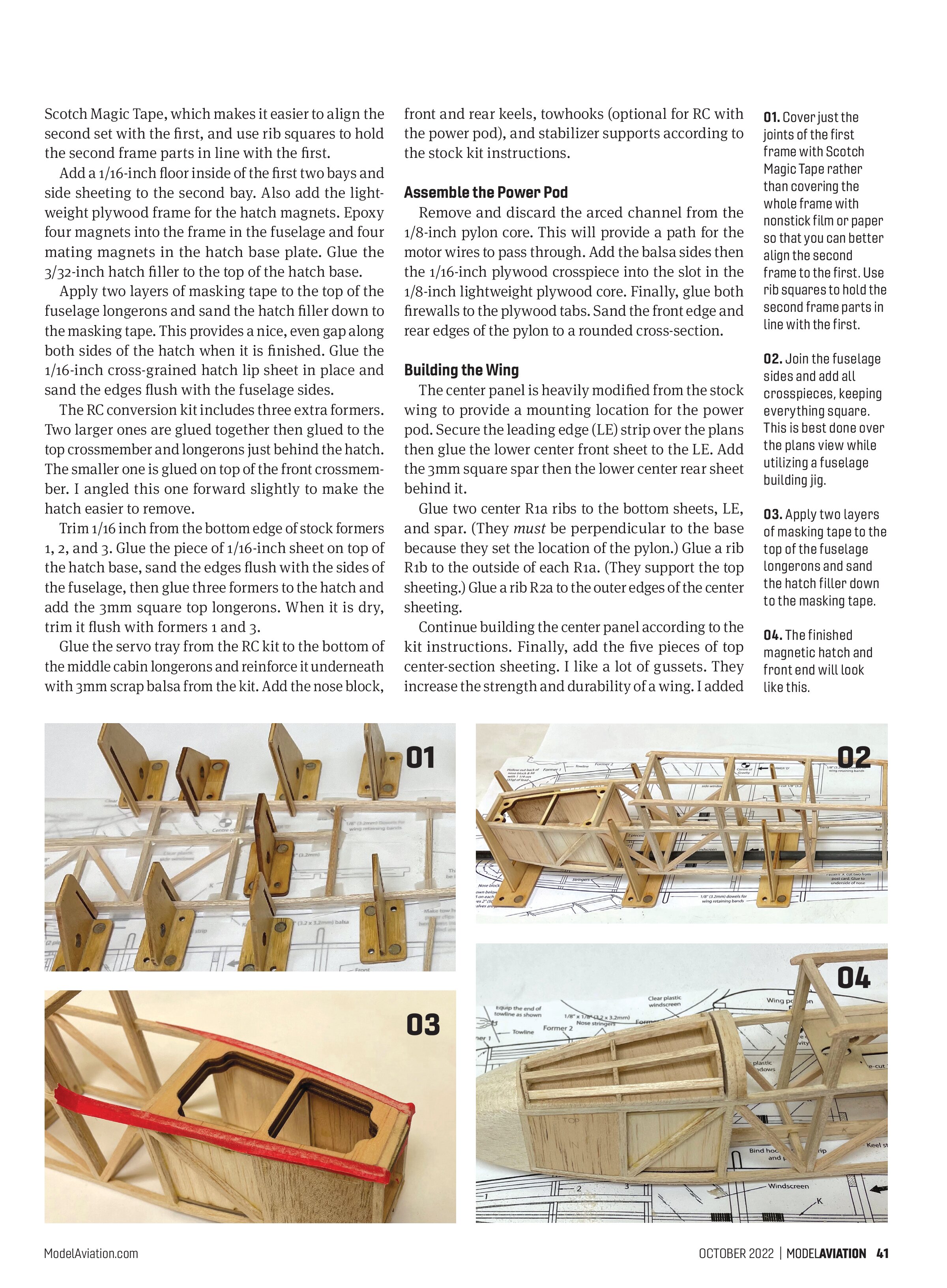
A Building Trip Down Memory Lane
Converting a Keil Kraft Invader to electric RC
Mark Freeland
retro rc@live.com
Photos by the author

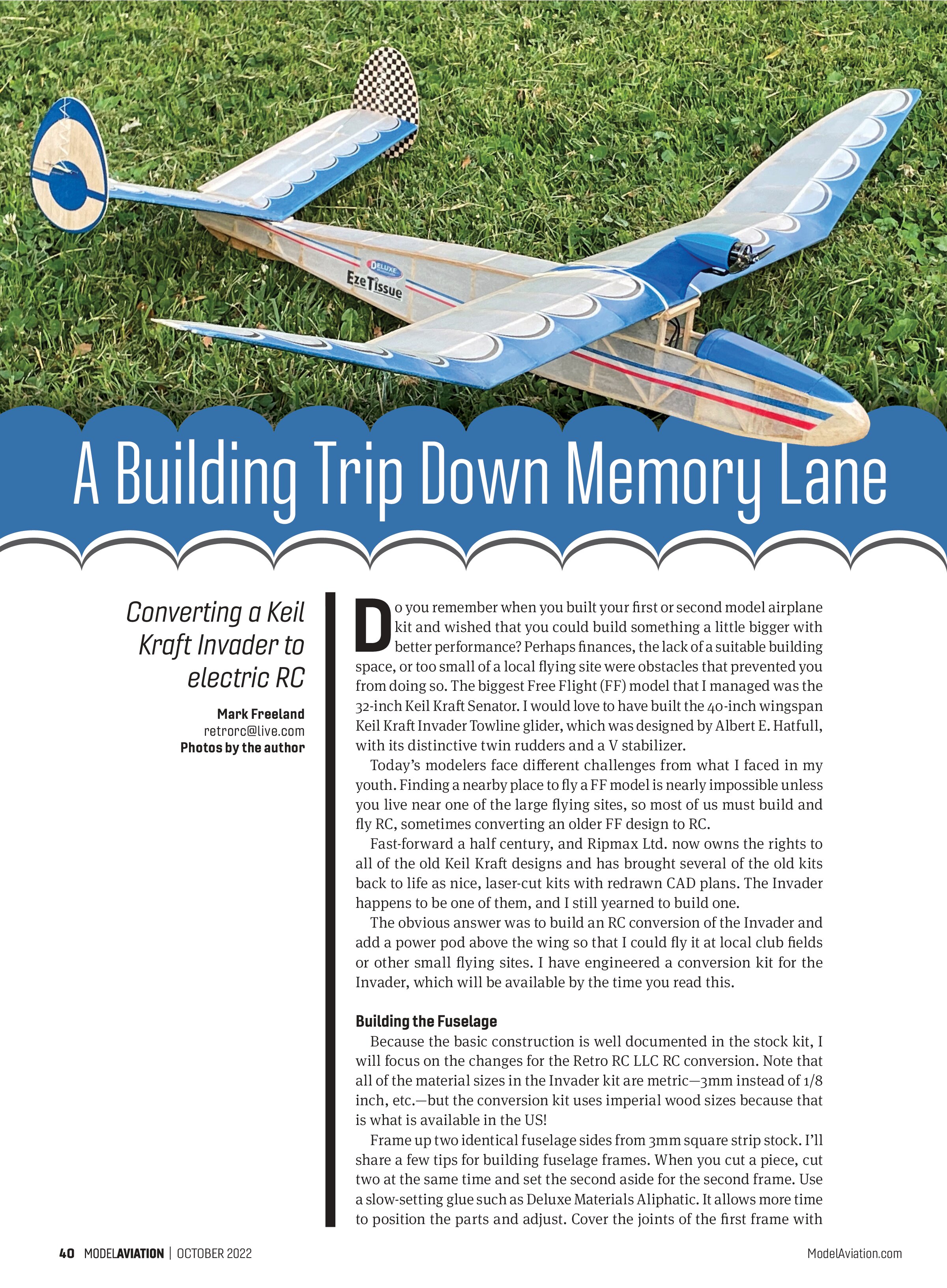
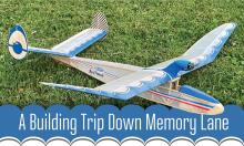
Do you remember when you built your first or second model airplane kit and wished that you could build something a little bigger with better performance? Perhaps finances, the lack of a suitable building space, or too small of a local flying site were obstacles that prevented you from doing so. The biggest Free Flight (FF) model that I managed was the 32-inch Keil Kraft Senator. I would love to have built the 40-inch wingspan Keil Kraft Invader Towline glider, which was designed by Albert E. Hatfull, with its distinctive twin rudders and a V stabilizer.
Today’s modelers face different challenges from what I faced in my youth. Finding a nearby place to fly a FF model is nearly impossible unless you live near one of the large flying sites, so most of us must build and fly RC, sometimes converting an older FF design to RC.
Fast-forward a half century, and Ripmax Ltd. now owns the rights to all of the old Keil Kraft designs and has brought several of the old kits back to life as nice, laser-cut kits with redrawn CAD plans. The Invader happens to be one of them, and I still yearned to build one.
The obvious answer was to build an RC conversion of the Invader and add a power pod above the wing so that I could fly it at local club fields or other small flying sites. I have engineered a conversion kit for the Invader, which will be available by the time you read this.
Building the Fuselage
Because the basic construction is well documented in the stock kit, I will focus on the changes for the Retro RC LLC RC conversion. Note that all of the material sizes in the Invader kit are metric—3mm instead of 1/8 inch, etc.—but the conversion kit uses imperial wood sizes because that is what is available in the US!
Frame up two identical fuselage sides from 3mm square strip stock. I’ll share a few tips for building fuselage frames. When you cut a piece, cut two at the same time and set the second aside for the second frame. Use a slow-setting glue such as Deluxe Materials Aliphatic. It allows more time to position the parts and adjust. Cover the joints of the first frame with Scotch Magic Tape, which makes it easier to align the second set with the first, and use rib squares to hold the second frame parts in line with the first.
Add a 1/16-inch floor inside of the first two bays and side sheeting to the second bay. Also add the lightweight plywood frame for the hatch magnets. Epoxy four magnets into the frame in the fuselage and four mating magnets in the hatch base plate. Glue the 3/32-inch hatch filler to the top of the hatch base.
Apply two layers of masking tape to the top of the fuselage longerons and sand the hatch filler down to the masking tape. This provides a nice, even gap along both sides of the hatch when it is finished. Glue the 1/16-inch cross-grained hatch lip sheet in place and sand the edges flush with the fuselage sides.
The RC conversion kit includes three extra formers. Two larger ones are glued together then glued to the top crossmember and longerons just behind the hatch. The smaller one is glued on top of the front crossmember. I angled this one forward slightly to make the hatch easier to remove.
Trim 1/16 inch from the bottom edge of stock formers 1, 2, and 3. Glue the piece of 1/16-inch sheet on top of the hatch base, sand the edges flush with the sides of the fuselage, then glue three formers to the hatch and add the 3mm square top longerons. When it is dry, trim it flush with formers 1 and 3.
Glue the servo tray from the RC kit to the bottom of the middle cabin longerons and reinforce it underneath with 3mm scrap balsa from the kit. Add the nose block, front and rear keels, towhooks (optional for RC with the power pod), and stabilizer supports according to the stock kit instructions.
Assemble the Power Pod
Remove and discard the arced channel from the 1/8-inch pylon core. This will provide a path for the motor wires to pass through. Add the balsa sides then the 1/16-inch plywood crosspiece into the slot in the 1/8-inch lightweight plywood core. Finally, glue both firewalls to the plywood tabs. Sand the front edge and rear edges of the pylon to a rounded cross-section.
Building the Wing
The center panel is heavily modified from the stock wing to provide a mounting location for the power pod. Secure the leading edge (LE) strip over the plans then glue the lower center front sheet to the LE. Add the 3mm square spar then the lower center rear sheet behind it.
Glue two center R1a ribs to the bottom sheets, LE, and spar. (They must be perpendicular to the base because they set the location of the pylon.) Glue a rib R1b to the outside of each R1a. (They support the top sheeting.) Glue a rib R2a to the outer edges of the center sheeting.
Continue building the center panel according to the kit instructions. Finally, add the five pieces of top center-section sheeting. I like a lot of gussets. They increase the strength and durability of a wing. I added


one to the LE and trailing edge (TE) joints of each rib. These are optional and are not included in the kit.
The wingtip panels are built following the Keil Kraft instructions. Sand the TE of the center wing panel and laminated wingtips to profile before joining them to the main wing panel. Finish the wing by attaching the wingtips as described in the kit’s instructions.
Stabilizer and Rudders
Build each stabilizer half over the plans as normal. When they are dry, join them with the correct dihedral according to the plans. Add the two bottom-half stabilizer ribs included in the RC conversion kit to either side of the dihedral joint.
Cut a 1/4 x 1/16-inch notch in the top of T3 and T4. The front of the notch should be 3/4 inch behind the spar. Put an acute angled hole in a strip of 1/16 x 1/4-inch balsa using a 1/16-inch drill bit for the Teflon tube to pass through. Glue this strip into the notches as shown in Photo 11 so that the end of the slot is roughly 1/4 inch inboard of the S4 rib and trim the ends flush with ribs S3 and S4. Repeat on the other side.
Cut the Teflon tube in half and use its natural curl to help locate the best route through the stabilizer so that the end will exit forward in the bottom center section of the stabilizer. Use a 1/16-inch drill bit to pierce the ribs in the best position for this to pass through. Feed the tube through the holes, leaving it long by a couple of inches at both ends. Secure to each rib and to the slot with a drop of medium CA or epoxy. Do not get any glue near the ends of the tubes. You will be stuck if you do!
Offer the stabilizer up to the fuselage saddle and pierce two 1/16-inch holes in the lower part of the front stabilizer support S1 for the two tubes to pass through. After the fuselage and stabilizer are covered, the stabilizer will be glued in place with the tubes passing through these holes. Shape the ends of the two pieces of 1/2-inch TE stock to a pleasing shape and glue one of them to the rear member of the left stabilizer. The right one will be hinged after covering.
Glue each of the two fin halves together according to the kit instructions. The rudders will be separated from the fin after they are covered with tissue. The final preparation before covering is to build the pull-pull cable and servo arm assembly and install this in the fuselage. It would be nearly impossible to do after covering.
Choose a long servo arm with ears on both sides. Pass the cable down the outer hole on one side through the 1-inch piece of 1/16-inch outer-diameter (OD) aluminum tube and up through the outer hole on the other end. Center the cable so that both sides are approximately the same length. Bend the Al tube so that it will sit neatly behind the central pivot of the arm and crimp gently with round-nose pliers to secure the cable.
Pass both loose ends of the cable through the two holes in S1 and tie them together so that they cannot go back into the fuselage while you are covering the model. Roll the servo end of the cable up and tuck it away in the radio compartment while you are covering the fuselage.
Covering the Model
You can cover the model using any covering method you like. I chose to cover it the traditional way with tissue and finish it with a water-based dope. Whatever you choose to cover it with, you should give the entire model a final sanding in preparation for it.
You should also seal the wood with thinned nitrate dope to harden it and increase its strength. This is important on the fin and rudders because water would likely cause the thin sheet wood to warp.
I covered the entire model with natural Eze Tissue by Deluxe Materials. The company’s Tissue Paste works well to adhere the tissue, which can be applied wet or dry. This tissue will shrink a lot after applying the water-based Eze Dope solution. If you apply it wet, wet it in a shallow bath containing a 5% solution of Eze Dope and 95% water.
For the sealing coats, you will want to use 30% Eze Dope and 70% water. You need to apply three or more thin coats to seal the tissue. There is no need to spray this stuff; it goes on nicely with a brush.
I also chose to decorate the Invader using Deluxe Materials’ new Designer tissue, which is preprinted with a number of interesting designs. In fact, all of the designs on the model, with the exception of the blue on the outer sides of the fins and rudders, came from one sheet of the Designer tissue, including the nice checkers on the inside of the fins.
I found the best technique to add the trim tissue was after the second coat of Eze Dope had dried. Place the cut-out dry trim over the model. After adjusting its position, tack it down by applying a light coat of


pure water. This will allow you to make a final adjustment before securing it in place with a coat of 30% Eze Dope. After applying the trim, apply two or more coats of 30% Eze Dope.
Use the paper template in the kit to mark the location of the rudder and the hinge stitching holes on the covered fins. Drill the holes for stitching with a 1/32-inch drill bit in a pin vice then cut the rudder free and sand roughly 1/32 inch off of the bottom edge so that it will not scrub against the fin as it swings on the hinge.
Hinge the rudder by stitching it with the provided Dacron thread. The easy way to make a needle is to soak roughly an inch of the end of the thread in thin CA and let it cure. This can be repeated as many times as needed to make a usable needle. Sew the rudder on with a figure-of-8 stitch when viewed from the end; viewed from either side, it will look like a zig-zag pattern.
Start with loose stitches. After it is fully stitched, use toothpicks to pull each stitch tight as you work from one end to the other. Secure each stitch in the hole with a tiny drop of white glue applied with a toothpick. Don’t use CA because the stitching will become brittle. Trim off the ends after the glue has dried and you will have a free-moving hinge.
Installing the Radio, Motor, and Hardware
Glue the wing hold-down dowels into their gussets. There should be roughly 3/8 inch or so protruding from either side. There is no need for dowels for the stabilizer because it will be glued in place.
Bolt the motor to the front of the power pod with the machine screws that came with the motor. Leave the propeller off for the moment. Feed the motor wires through the channel in the pod. Feed the wires through the wing center and glue the base of the pod into the slot in the wing.
Solder a three-way connector to the motor leads and mate the connector to the ESC while you are at it. A note about propellers. They are sold in sets of four: two with clockwise rotation and two with counter-clockwise rotation. Although it is conventional on fixed-wing models to run the propeller counterclockwise when viewed from the front, it is fine to run a clockwise rotation on this power pod installation.
The RC conversion kit comes with a 3D-printed fairing for the power pod. Slide this on from the rear and spring it outward until its front snaps over the firewall. Add a small drop of epoxy or CA glue at the rear to permanently lock it in place.
Screw the two servos into the servo tray. The elevator servo goes on the left with the output arm at the rear and the rudder servo goes on the right with the output at the front. Carefully unravel the pull-pull wire and install the servo arm so that the wires are not twisted inside of the fuselage and pull the slack out the rear.
Trim the ends of the Teflon tubes on the stabilizer so that there is 1 inch coming out of the front and 1/2 inch out either side on the top of the surfaces. Untie the ends of the pull-pull cable (or cut off the knot) and feed the pull-pull cables through the tubes. Pull up the slack until you can push the front tube ends through the holes in S1. Carefully align the stabilizer to the fuselage and glue it in place.
Next, glue the fins to the ends of the stabilizer.


rudder template has guide marks to show where it will align with the LE and TE. Use these marks to push a pin through the front and the back into the end of the stabilizer. I suggest doing one side at a time.
Bend two pairs of the small wire hooks that are shown in Photo 22 from the 0.024-inch stainless steel wire. These are used to attach the dental bands that provide the return force to pull the rudders outward. The longer-legged hook goes on the rudder and the short one on the fin. Superglue or epoxy these in place. When dry, stretch a 3/8-inch medium or heavy dental band around both hooks twice.
Hook up the receiver, ESC, and battery to the two servos. Check that the subtrim and trims are all zeroed and that the servo arms are straight across the fuselage. Leave the power on while hooking up the rudder’s cables and elevator pushrod.
Prepare two aluminum crimps by cutting off a 3/16-inch length of 1/16-inch OD aluminum tube and deburring both ends of each. At the location shown on the rudder template, make two 1/32-inch holes, one above and one below the leg of the long hook.
Feed the cable through an aluminum tube crimp then through the lower hole. While holding the rudder straight, crease the cable at the point where it will pass over the wire hook (with the servo at neutral). Thread it back through the top hole and back through the aluminum crimp. Check that the cable is still the correct length for a straight rudder then crimp the 1/16-inch Al tube with a pair of round-nose pliers.
Add a small blob of epoxy as a security measure (but don’t let it run down the wire to the Teflon tube) then trim off the excess cable. Repeat this procedure for the other rudder. Verify that the rudder controls work smoothly and, if needed, add a second dental band on both sides if more return force is required.
Cut the 1/32-inch stainless steel spring wire in half. With one half, make a Z-bend near one end and a few shallow “kinks” along the remaining length. (These help the CA grip the wire better.) Attach this to the carbon-fiber pushrod using 1 inch of the heat-shrink tube and a few drops of thin CA after the tube has been shrunk.
Make a simple L-bend for the other end of the pushrod and attach it to the other end of the pushrod with heat-shrink tube, but do not apply glue yet. Put a servo arm on the Z-bend then feed the pushrod through the front window opening and down the fuselage so that it exits on the right side above the crossbrace in the last bay. With the servo at the neutral position, install the arm on the servo. Slide the plywood elevator horn over the back of the elevator in a position that works for the pushrod. Glue the horn in place on the elevator.
Adjust the length of the pushrod so that the elevator is level, and then secure the pushrod end to the pushrod with a couple of drops of thin CA applied to the ends of the heat-shrink tube. Finally, lock the pushrod to the elevator horn using the Du-Bro E/Z Link provided in the kit.
All that remains to be done is to install the windshield according to the Keil Kraft kit instructions, and add ballast to the cavity in the nose block to get the glider to balance on the wing spar.
Using a 17-gram 300 mAh battery, I had to add 25 grams in the nose block to get the correct center of gravity. This brought the ready-to-fly weight up to 200 grams.
SOURCES:
Ripmax
mail@ripmax.com
www.ripmax.com
Retro RC
retrorc@live.com
www.retrorc.us.com
Deluxe Materials
sales@deluxematerials.co.uk
www.deluxematerials.com