RC SCALE AEROBATICS
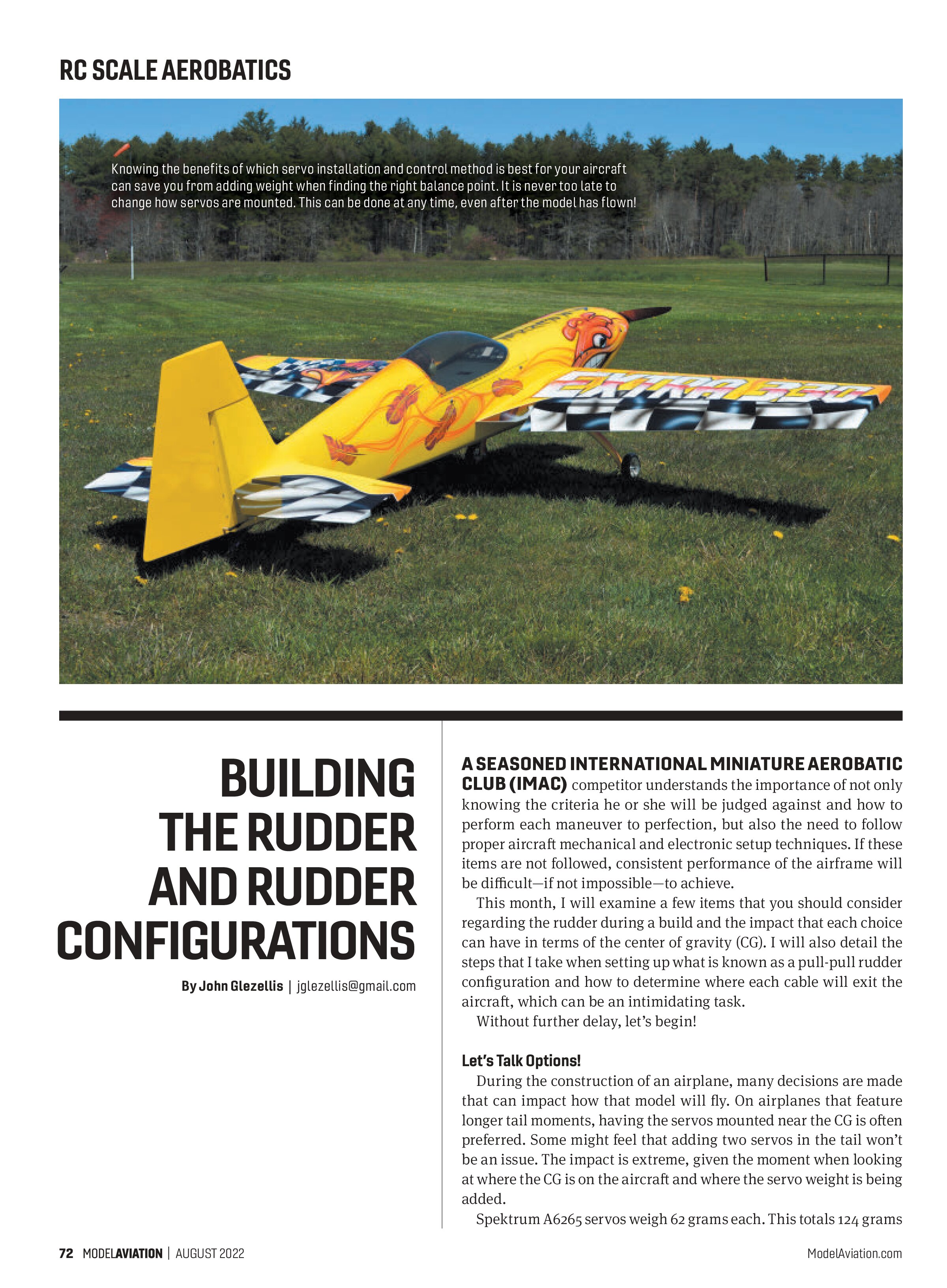
Knowing the benefits of which servo installation and control method is best for your aircraft can save you from adding weight when finding the right balance point. It is never too late to change how servos are mounted. This can be done at any time, even after the model has flown!
BUILDING
THE RUDDER
AND RUDDER
CONFIGURATIONS
By John Glezellis | jglezellis@gmail.com
A SEASONED INTERNATIONAL MINIATURE AEROBATIC CLUB (IMAC) competitor understands the importance of not only knowing the criteria he or she will be judged against and how to perform each maneuver to perfection, but also the need to follow proper aircraft mechanical and electronic setup techniques. If these items are not followed, consistent performance of the airframe will be difficult—if not impossible—to achieve.
This month, I will examine a few items that you should consider regarding the rudder during a build and the impact that each choice can have in terms of the center of gravity (CG). I will also detail the steps that I take when setting up what is known as a pull-pull rudder configuration and how to determine where each cable will exit the aircraft, which can be an intimidating task.
Without further delay, let’s begin!
Let’s Talk Options!
During the construction of an airplane, many decisions are made that can impact how that model will fly. On airplanes that feature longer tail moments, having the servos mounted near the CG is often preferred. Some might feel that adding two servos in the tail won’t be an issue. The impact is extreme, given the moment when looking at where the CG is on the aircraft and where the servo weight is being added.
Spektrum A6265 servos weigh 62 grams each. This totals 124 grams for two servos, excluding the weight of the servo arms, linkages, and servo extensions, which all add up! I recently purchased a 2.7-meter 3W Extra 330S. I installed the Spektrum rudder servos near the CG in a pull-pull configuration, which is also known as a closed-loop cable control system. I knew this model was sensitive for servo placement because it used a two-cylinder engine.
With this rudder setup, multiple servos near the CG have connections to the control horns on both sides of the control surface. As a result, each deflection direction is a “pull” from the servo to the control horn.
Aircraft that feature heavier engines, such as a four-cylinder engine, often benefit by having servos in the tail, which brings me to the next rudder arrangement option.
In a push-pull configuration, the servo or multiple servos are located in the tail of the aircraft with a push-pull linkage arrangement. For the linkage, titanium turnbuckles are commonly used, such as Hangar 9 Pro-Links. For accurate control of the aircraft, “slop” in the linkage system must be kept to a minimum.
If you are unsure about which rudder/servo configuration is best for your model, I recommend that the airframe be completed and ready to fly, except for installing the rudder servos, main batteries, and receiver. Check the CG and try multiple locations for the rudder servos and main batteries. When you are satisfied, install the rudder servos in the desired position, as well as the batteries and receiver. Again, the airplane must be in a ready-to-fly configuration for this to be beneficial.

Lead by Example
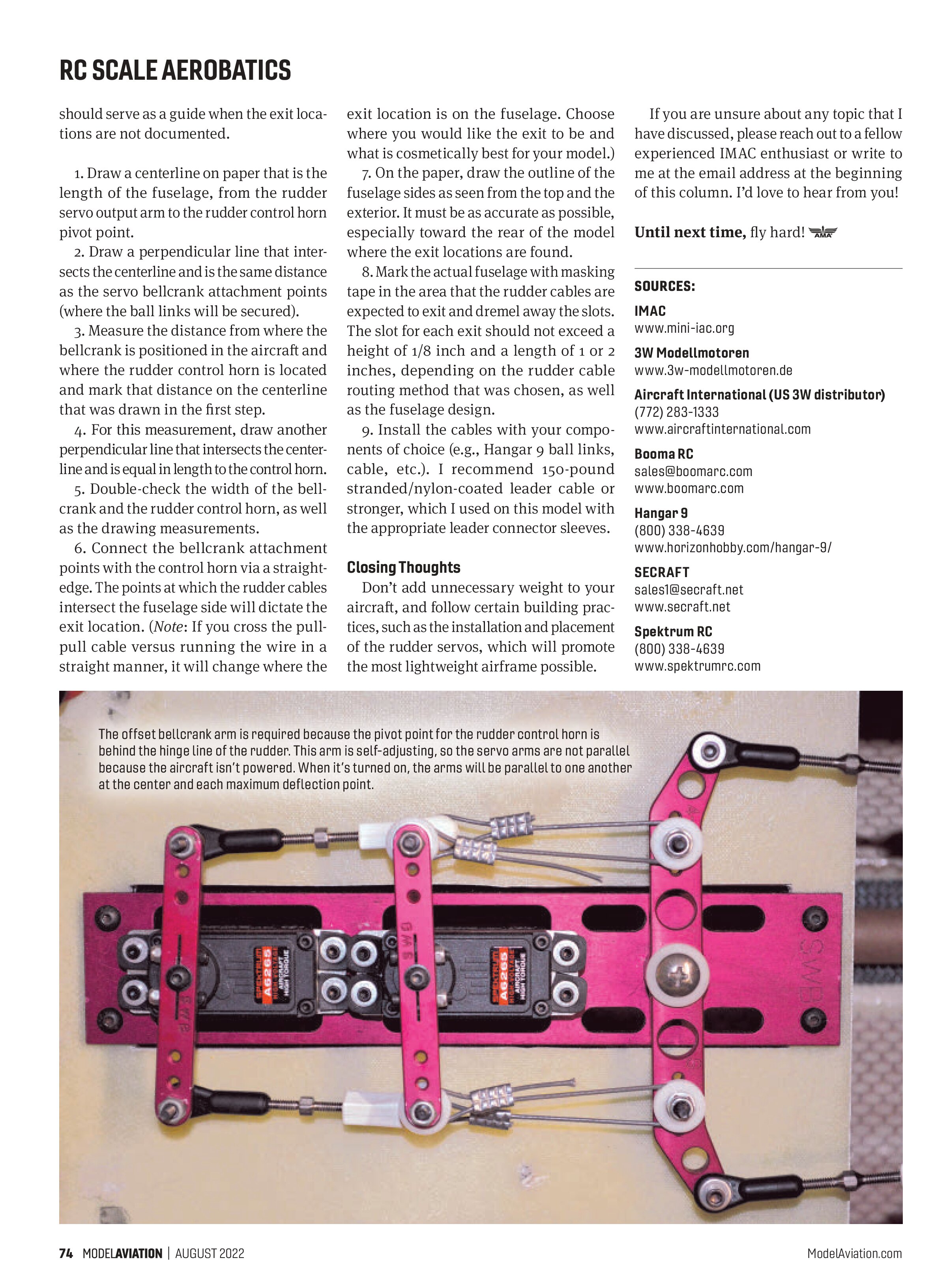
The rudder servos for the 3W Extra 330 were installed on an SWB servo tray. Although inventory of SWB products is limited because the company is no longer in business, other options are available from companies such as Booma RC and SECRAFT.
The Extra 330 uses the two high-torque Spektrum servos noted previously and a two-servo tray option. For larger models, and depending on the torque available from each servo, tray options for three or four servos exist.
It should be stated that bellcranks are not just for multiple servos. Even if you are using a single servo for the rudder, using a bellcrank is beneficial because the tension of the cables is not loaded on the output gear of the servo. A bellcrank will ensure smooth movement on behalf of the servo when rudder input is applied.
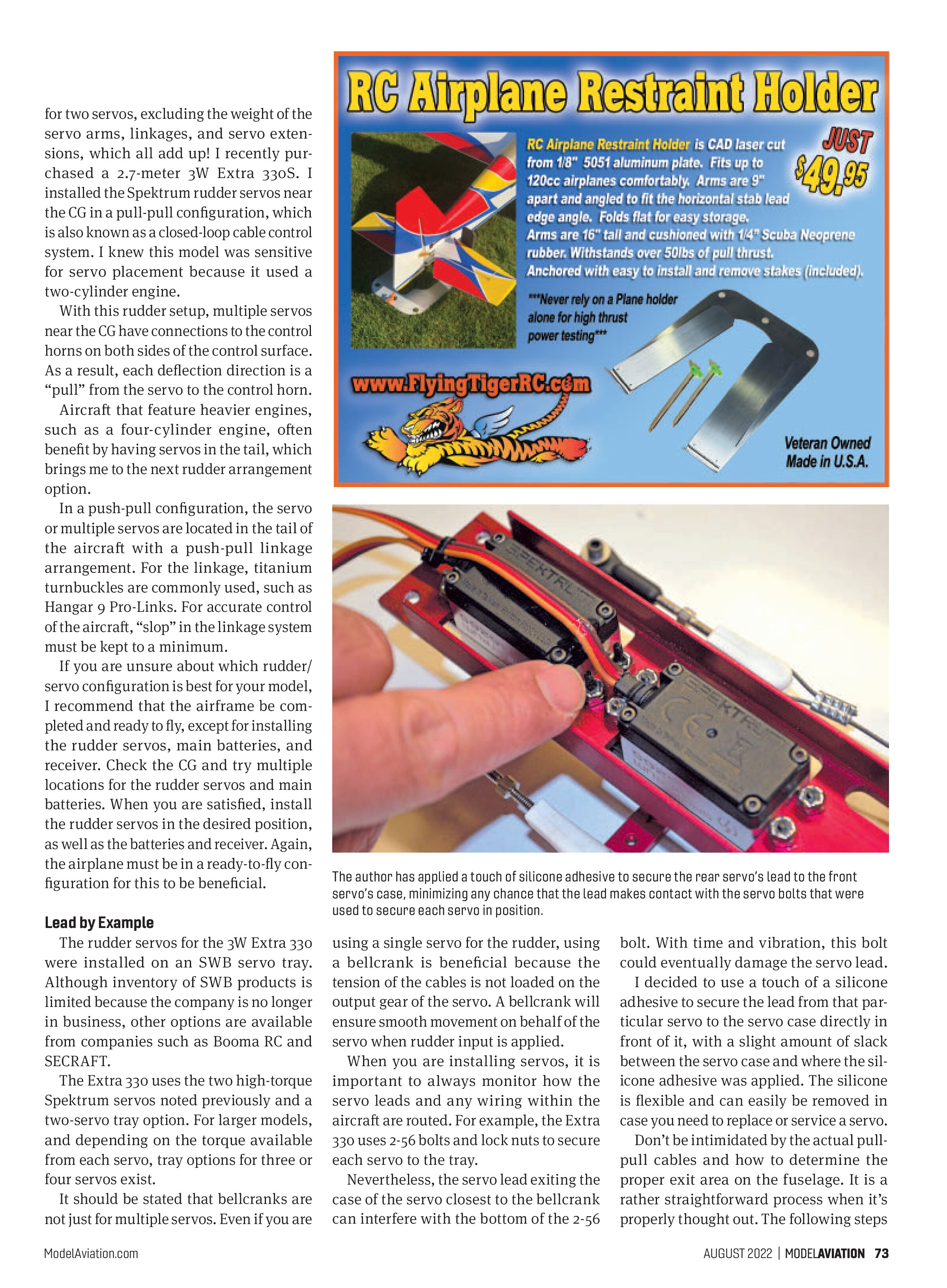
When you are installing servos, it is important to always monitor how the servo leads and any wiring within the aircraft are routed. For example, the Extra 330 uses 2-56 bolts and lock nuts to secure each servo to the tray.
Nevertheless, the servo lead exiting the case of the servo closest to the bellcrank can interfere with the bottom of the 2-56 bolt. With time and vibration, this bolt could eventually damage the servo lead.

I decided to use a touch of silicone adhesive to secure the lead from that particular servo to the servo case directly in front of it, with a slight amount of slack between the servo case and where the silicone adhesive was applied. The silicone is flexible and can easily be removed in case you need to replace or service a servo.
Don’t be intimidated by the actual pull-pull cables and how to determine the proper exit area on the fuselage. It is a rather straightforward process when it’s properly thought out. The following steps
should serve as a guide when the exit locations are not documented.
- Draw a centerline on paper that is the length of the fuselage, from the rudder servo output arm to the rudder control horn pivot point.
- Draw a perpendicular line that intersects the centerline and is the same distance as the servo bellcrank attachment points (where the ball links will be secured).
- Measure the distance from where the bellcrank is positioned in the aircraft and where the rudder control horn is located and mark that distance on the centerline that was drawn in the first step.
- For this measurement, draw another perpendicular line that intersects the centerline and is equal in length to the control horn.
- Double-check the width of the bellcrank and the rudder control horn, as well as the drawing measurements.
- Connect the bellcrank attachment points with the control horn via a straight-edge. The points at which the rudder cables intersect the fuselage side will dictate the exit location. (Note: If you cross the pull-pull cable versus running the wire in a straight manner, it will change where the exit location is on the fuselage. Choose where you would like the exit to be and what is cosmetically best for your model.)
- On the paper, draw the outline of the fuselage sides as seen from the top and the exterior. It must be as accurate as possible, especially toward the rear of the model where the exit locations are found.
- Mark the actual fuselage with masking tape in the area that the rudder cables are expected to exit and dremel away the slots. The slot for each exit should not exceed a height of 1/8 inch and a length of 1 or 2 inches, depending on the rudder cable routing method that was chosen, as well as the fuselage design.
- Install the cables with your components of choice (e.g., Hangar 9 ball links, cable, etc.). I recommend 150-pound stranded/nylon-coated leader cable or stronger, which I used on this model with the appropriate leader connector sleeves.
Closing Thoughts
Don’t add unnecessary weight to your aircraft, and follow certain building practices, such as the installation and placement of the rudder servos, which will promote the most lightweight airframe possible.
If you are unsure about any topic that I have discussed, please reach out to a fellow experienced IMAC enthusiast or write to me at the email address at the beginning of this column. I’d love to hear from you!
Until next time, fly hard!
SOURCES:
IMAC
www.mini-iac.org
3W Modellmotoren
www.3w-modellmotoren.de
Aircraft International (US 3W distributor)
(772) 283-1333
www.aircraftinternational.com
Booma RC
sales@boomarc.com
www.boomarc.com
Hangar 9
(800) 338-4639
www.horizonhobby.com/hangar-9/
SECRAFT
sales1@secraft.net
www.secraft.net
Spektrum RC
(800) 338-4639
www.spektrumrc.com