PROFESSIONAL
FUSELAGE
TAILBOOM
REPAIR

By Gordon Buckland | gordon@gatorf3b.com
ONE OF THE MOST common repairs on a modern sailplane is a broken tailboom. This month’s column is a real treat. We’ll learn how Dennis Harvey, an absolute genius in composite sailplane repairs, does it.
I have the dubious reputation of being a wizard at carbon-fiber repair. I say dubious because that also means I’ve made countless repairs—I have crashed so many times during the spot-landing learning curve. I’ve had decades of experience with composites throughout my career and also with my boating hobby. I share here the tricks to make a broken fuselage tailboom repair virtually invisible.
This first part that is included in the print magazine concludes with the model being ready to fly with an internal sleeve installed, but cosmetically, the fuselage still shows its wound. The second part is in the bonus content on the Model Aviation website and in Model Aviation Digital and focuses on making the damaged area nearly invisible and creating a significantly stronger repair.
The repair is on an F3B Pitbull, where the tailboom was broken clean in half. The pushrods were removed later and replaced because of delamination. The Pitbull has a particularly thick tailboom layup, but the techniques in this article also apply to the thinner layups of F3J and F5J fuselages.
Sleeving the Break Area
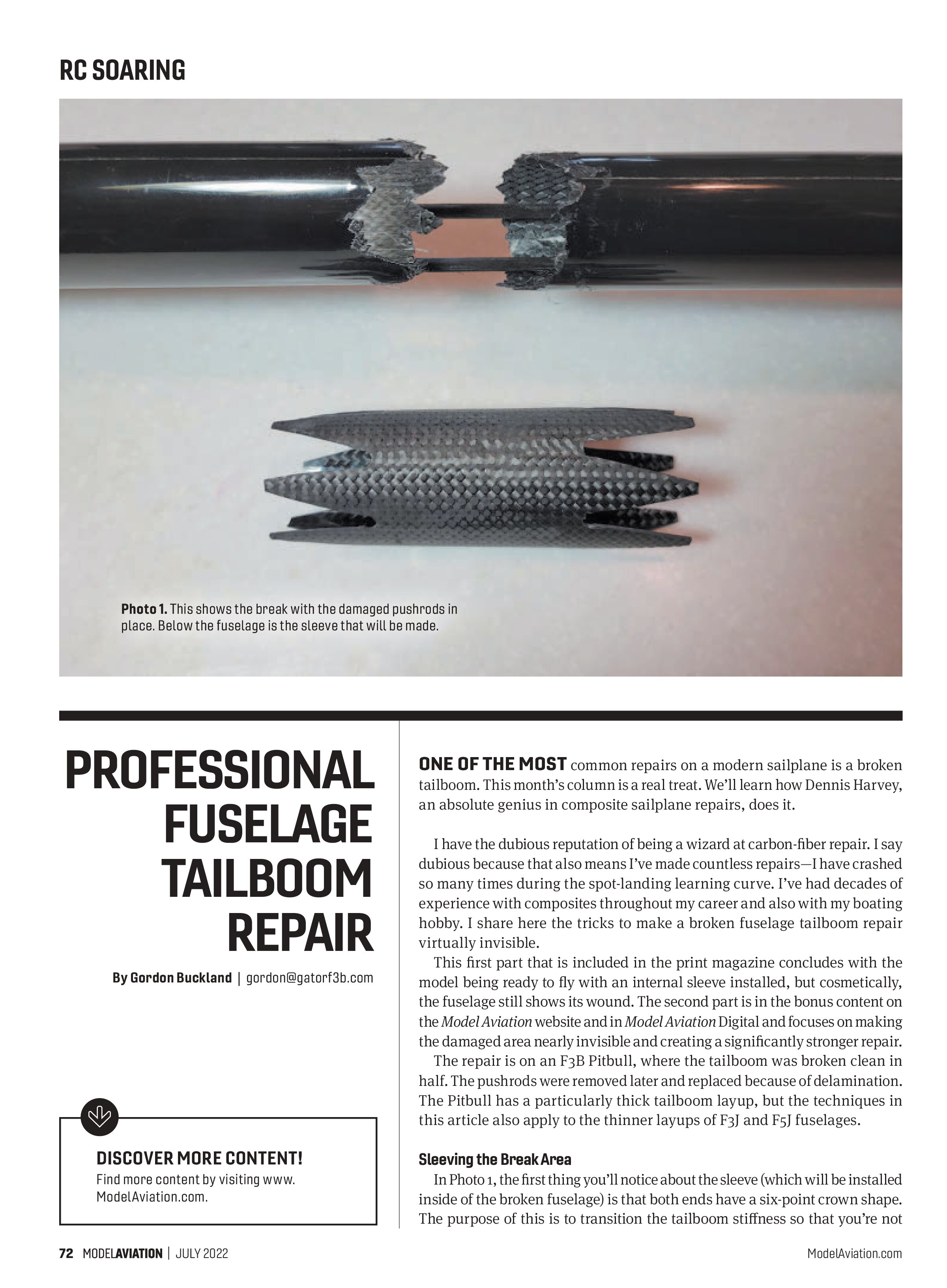
In Photo 1, the first thing you’ll notice about the sleeve (which will be installed inside of the broken fuselage) is that both ends have a six-point crown shape. The purpose of this is to transition the tailboom stiffness so that you’re not breaking the tailboom again at the edge of the sleeve on the next hard landing. This is highly likely without this transitional shape. The shape is easy to cut with a Dremel tool and a diamond cutting wheel.
Please note that the uncrowned length of the sleeve should be approximately 20mm greater on each side of the break. The crown points should be roughly 30mm. Use these measurements and your break to determine how long your sleeve should be in the next step.
Molding Your Sleeve
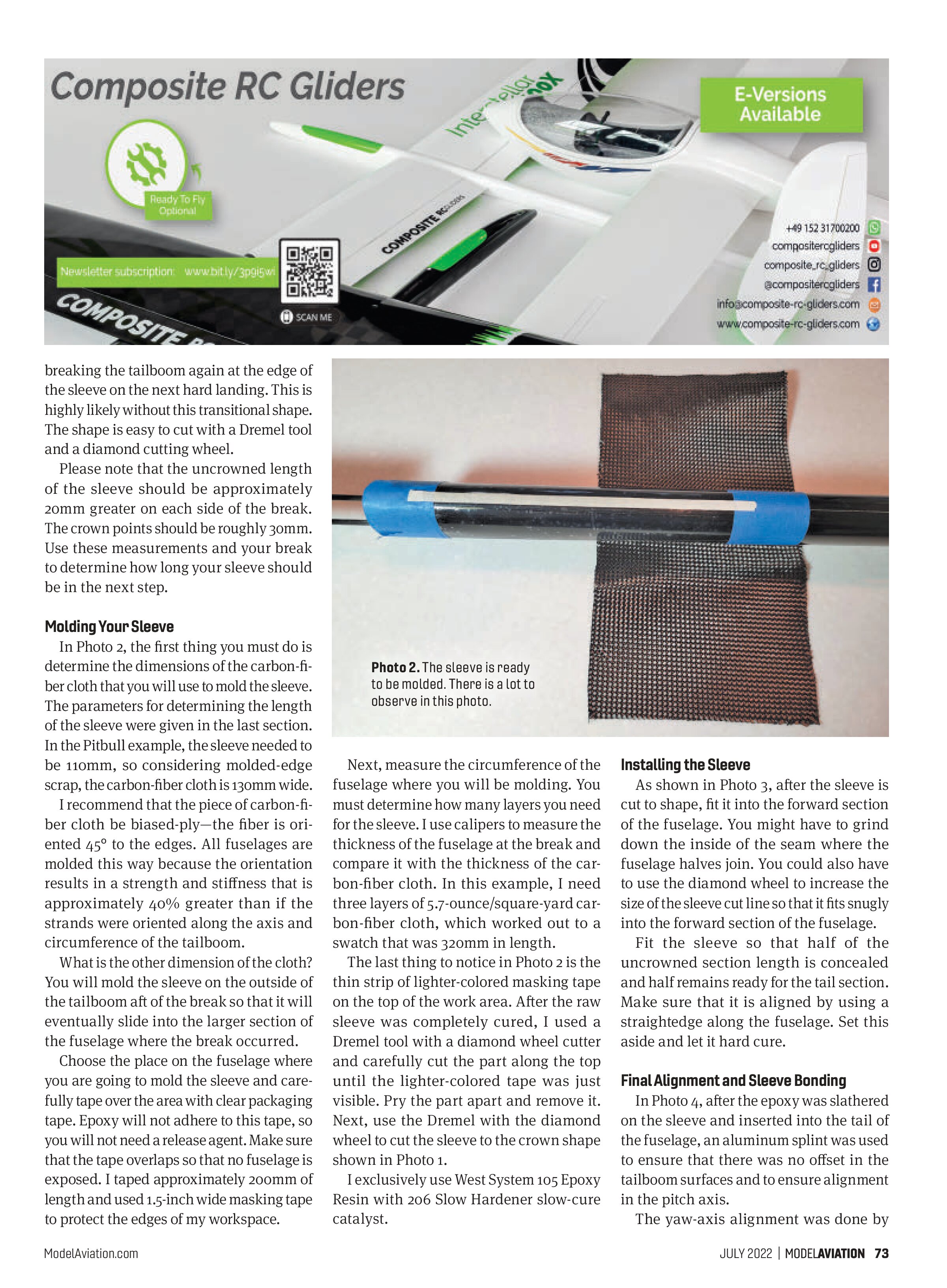
In Photo 2, the first thing you must do is determine the dimensions of the carbon-fiber cloth that you will use to mold the sleeve. The parameters for determining the length of the sleeve were given in the last section. In the Pitbull example, the sleeve needed to be 110mm, so considering molded-edge scrap, the carbon-fiber cloth is 130mm wide.
I recommend that the piece of carbon-fiber cloth be biased-ply—the fiber is oriented 45° to the edges. All fuselages are molded this way because the orientation results in a strength and stiffness that is approximately 40% greater than if the strands were oriented along the axis and circumference of the tailboom.
What is the other dimension of the cloth? You will mold the sleeve on the outside of the tailboom aft of the break so that it will eventually slide into the larger section of the fuselage where the break occurred.
Choose the place on the fuselage where you are going to mold the sleeve and carefully tape over the area with clear packaging tape. Epoxy will not adhere to this tape, so you will not need a release agent. Make sure that the tape overlaps so that no fuselage is exposed. I taped approximately 200mm of length and used 1.5-inch wide masking tape to protect the edges of my workspace.

Next, measure the circumference of the fuselage where you will be molding. You must determine how many layers you need for the sleeve. I use calipers to measure the thickness of the fuselage at the break and compare it with the thickness of the carbon-fiber cloth. In this example, I need three layers of 5.7-ounce/square-yard carbon-fiber cloth, which worked out to a swatch that was 320mm in length.
The last thing to notice in Photo 2 is the thin strip of lighter-colored masking tape on the top of the work area. After the raw sleeve was completely cured, I used a Dremel tool with a diamond wheel cutter and carefully cut the part along the top until the lighter-colored tape was just visible. Pry the part apart and remove it. Next, use the Dremel with the diamond wheel to cut the sleeve to the crown shape shown in Photo 1.
I exclusively use West System 105 Epoxy Resin with 206 Slow Hardener slow-cure catalyst.
Installing the Sleeve
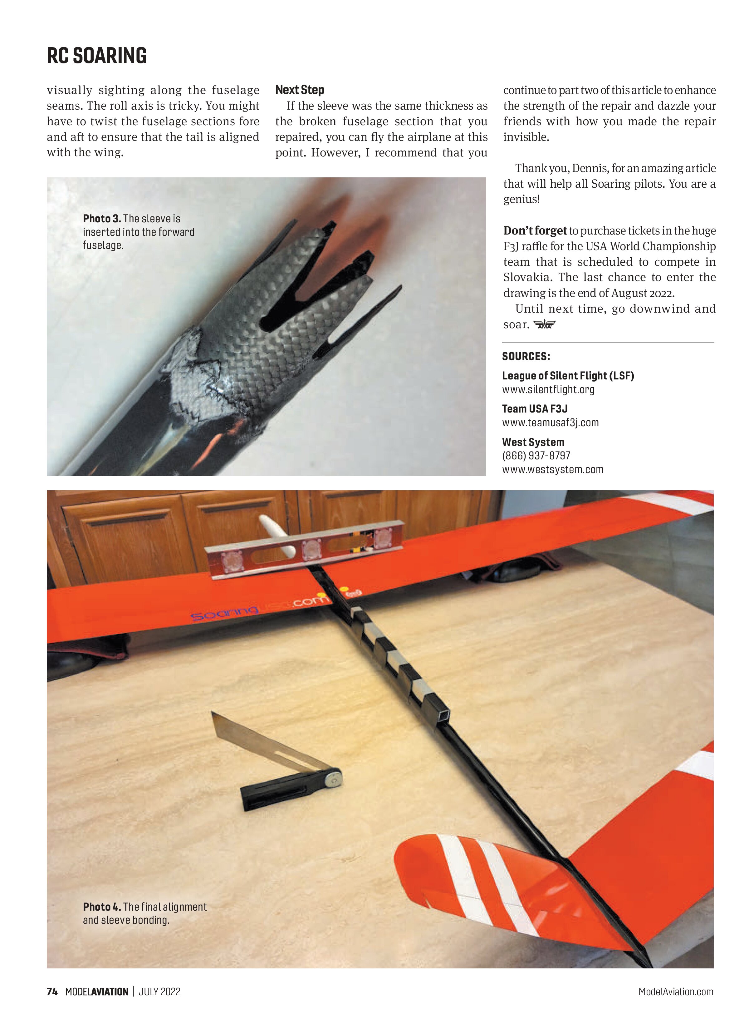
As shown in Photo 3, after the sleeve is cut to shape, fit it into the forward section of the fuselage. You might have to grind down the inside of the seam where the fuselage halves join. You could also have to use the diamond wheel to increase the size of the sleeve cut line so that it fits snugly into the forward section of the fuselage.
Fit the sleeve so that half of the uncrowned section length is concealed and half remains ready for the tail section. Make sure that it is aligned by using a straightedge along the fuselage. Set this aside and let it hard cure.
Final Alignment and Sleeve Bonding
In Photo 4, after the epoxy was slathered on the sleeve and inserted into the tail of the fuselage, an aluminum splint was used to ensure that there was no offset in the tailboom surfaces and to ensure alignment in the pitch axis.
The yaw-axis alignment was done by
visually sighting along the fuselage seams. The roll axis is tricky. You might have to twist the fuselage sections fore and aft to ensure that the tail is aligned with the wing.

Next Step
If the sleeve was the same thickness as the broken fuselage section that you repaired, you can fly the airplane at this point. However, I recommend that you
continue to part two of this article to enhance the strength of the repair and dazzle your friends with how you made the repair invisible.
Thank you, Dennis, for an amazing article that will help all Soaring pilots. You are a genius!
Don’t forget to purchase tickets in the huge F3J raffle for the USA World Championship team that is scheduled to compete in Slovakia. The last chance to enter the drawing is the end of August 2022.
Until next time, go downwind and soar.
SOURCES:
League of Silent Flight (LSF)
www.silentflight.org
Team USA F3J
www.teamusaf3j.com
West System
(866) 937-8797
www.westsystem.com