STUNT-FLYER RC
Turn a balsa
glider into an
RC model
By Tim Bailiff
casurfish@aol.com
Photos by the author

I feel blessed to have grown up in a flying family. My father, Dan, was a private pilot and loved flying. My older brother, Danny, grew up to be a commercial airline pilot. It’s no surprise that at 16, I became a private pilot, and to this day, I remain fascinated with anything that flies.
For as long as I can remember, I have loved building and flying model airplanes. As a youngster, I was particularly fond of simple balsa gliders. Like many of you, my squadron of model airplanes always included several 5¢ and 10¢ gliders. My personal favorites were those wonderful little gliders that were manufactured by North Pacific. You remember—the ones with the red plastic clip that attached the wing to the fuselage.
I ask you, how much fun would it be to install a tiny electric motor and convert one of those little gliders to RC? Well, using present-day micro electronics, that is exactly what I’ve done. What fun I’ve had revisiting one of my childhood favorites, and you can too. And this time, you can fly with full control. Hey, that means no more accidental landings on the roof!
If this seems interesting and fun to you, then I invite you to join me and fly nostalgic RC micro models.
The Name
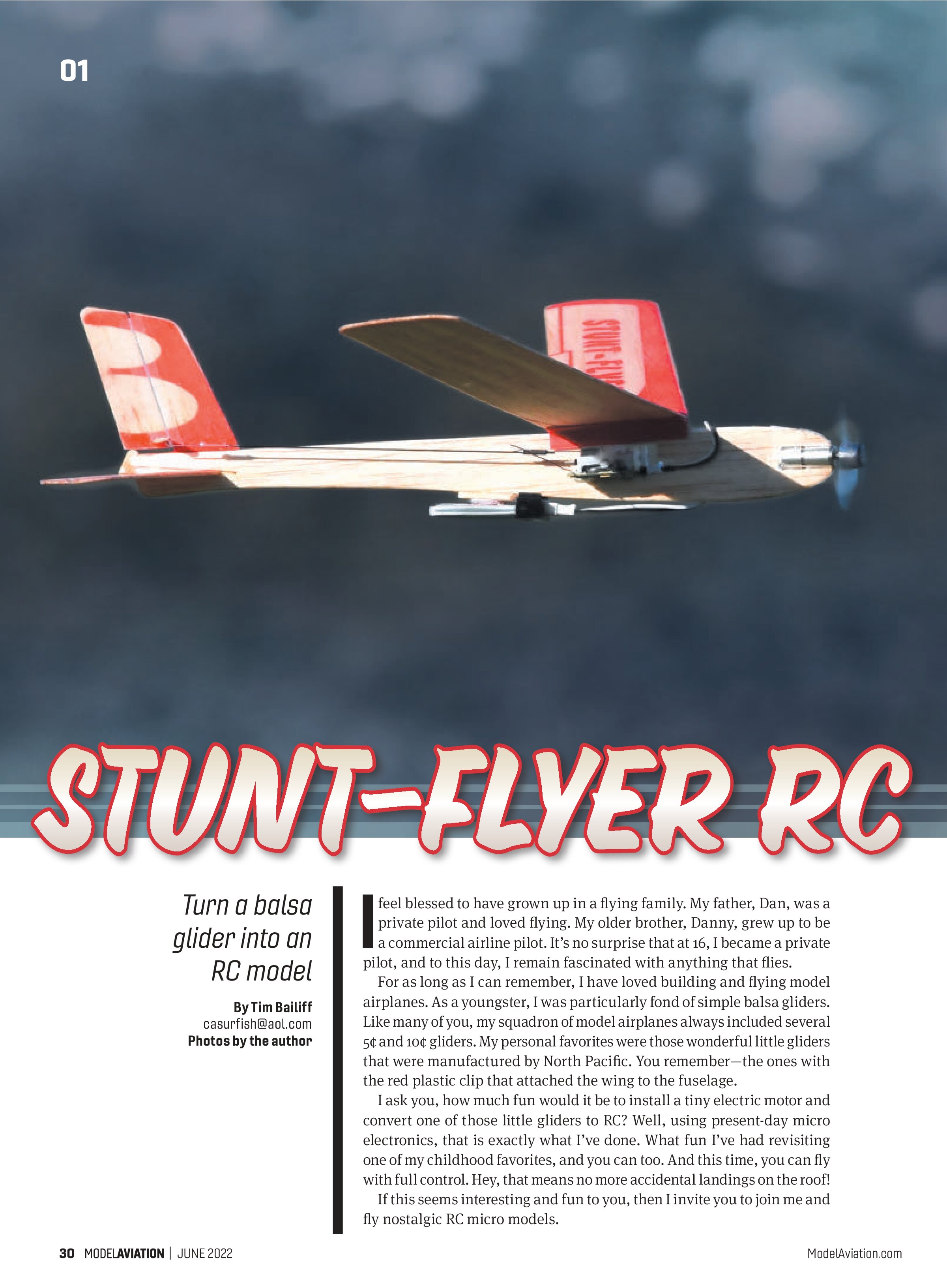
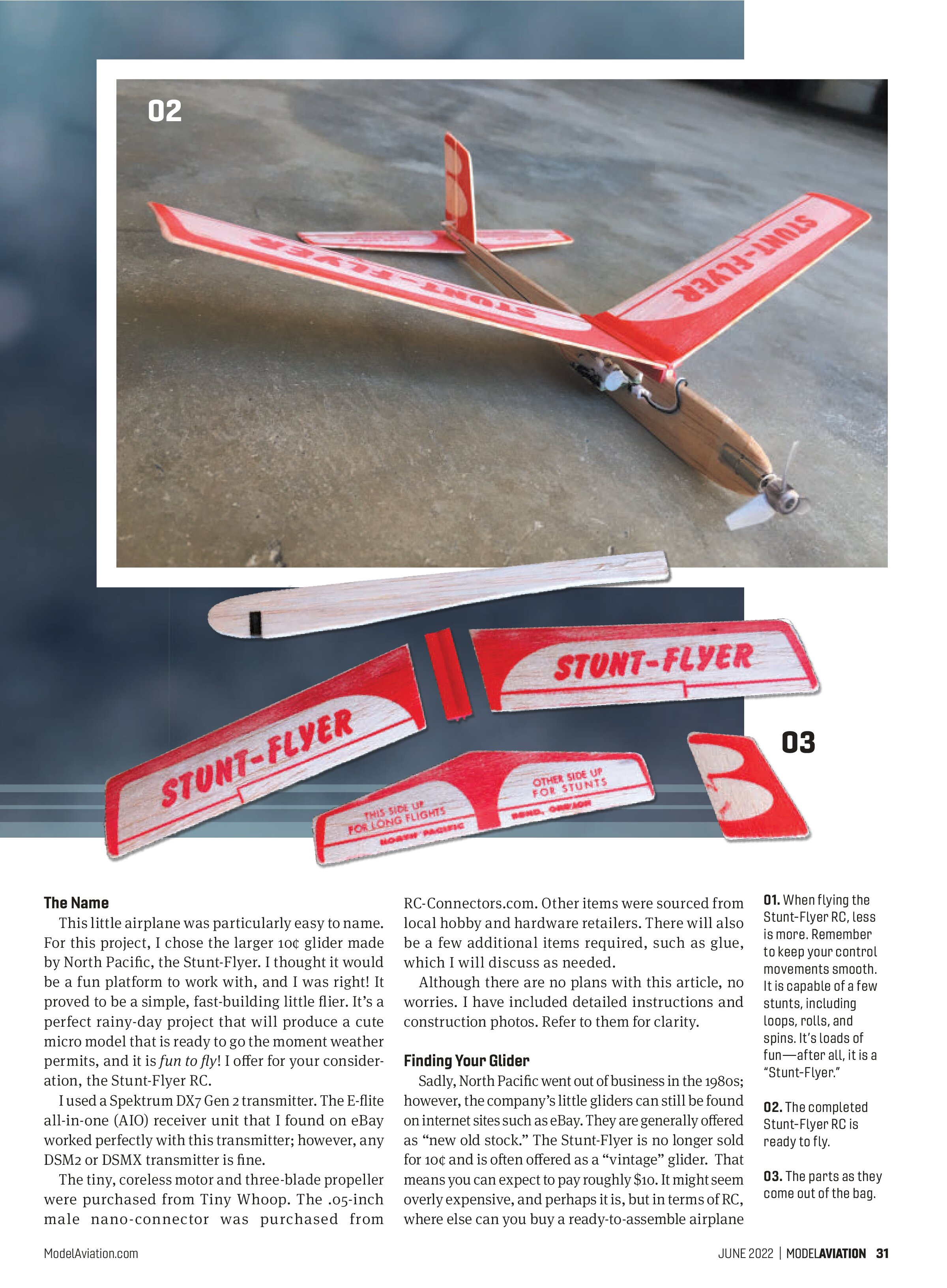
This little airplane was particularly easy to name. For this project, I chose the larger 10¢ glider made by North Pacific, the Stunt-Flyer. I thought it would be a fun platform to work with, and I was right! It proved to be a simple, fast-building little flier. It’s a perfect rainy-day project that will produce a cute micro model that is ready to go the moment weather permits, and it is fun to fly! I offer for your consideration, the Stunt-Flyer RC.
I used a Spektrum DX7 Gen 2 transmitter. The E-flite all-in-one (AIO) receiver unit that I found on eBay worked perfectly with this transmitter; however, any DSM2 or DSMX transmitter is fine.
The tiny, coreless motor and three-blade propeller were purchased from Tiny Whoop. The .05-inch male nano-connector was purchased from RC-Connectors.com. Other items were sourced from local hobby and hardware retailers. There will also be a few additional items required, such as glue, which I will discuss as needed.
Although there are no plans with this article, no worries. I have included detailed instructions and construction photos. Refer to them for clarity.
Finding Your Glider
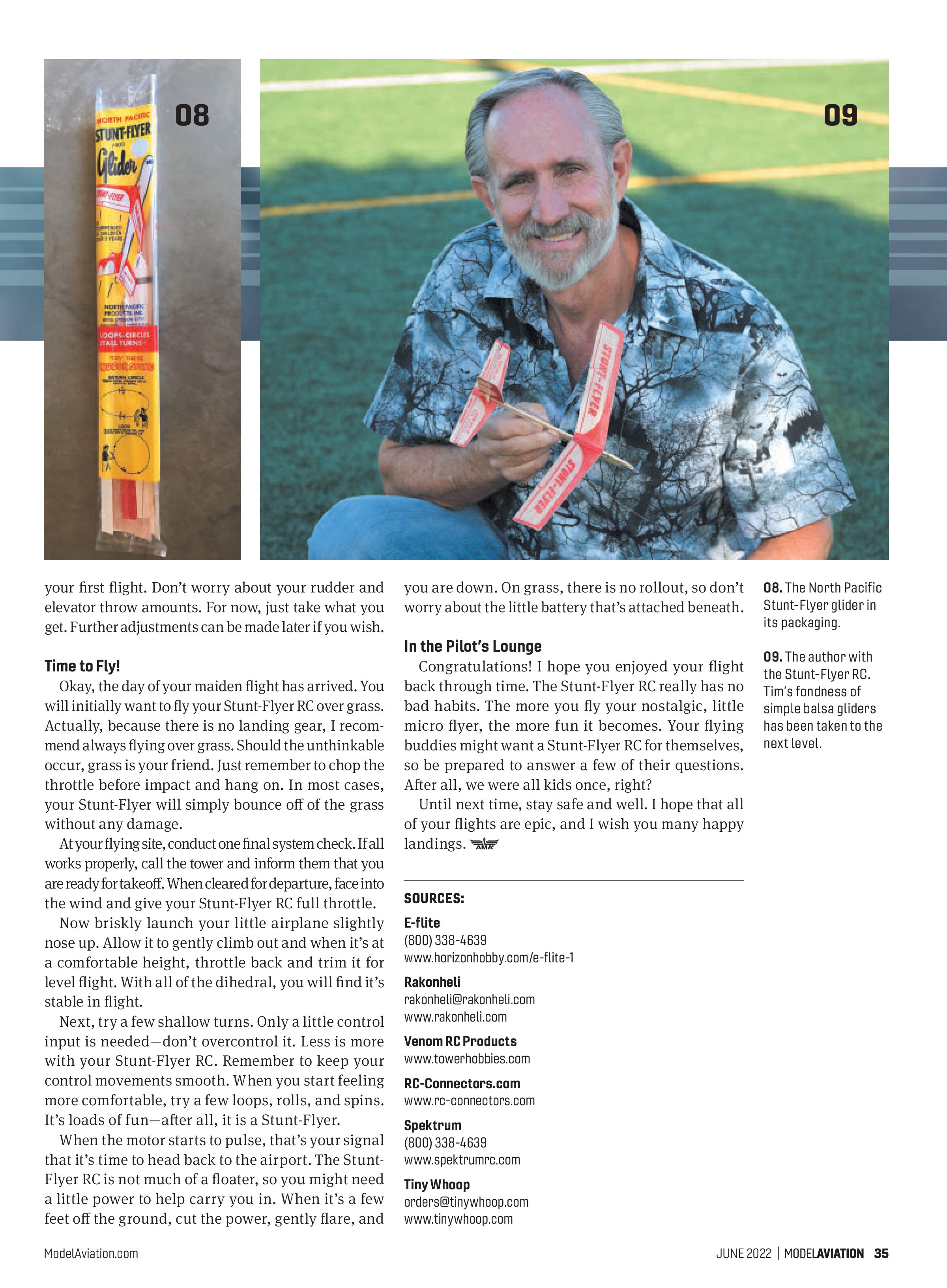
Sadly, North Pacific went out of business in the 1980s; however, the company’s little gliders can still be found on internet sites such as eBay. They are generally offered as “new old stock.” The Stunt-Flyer is no longer sold for 10¢ and is often offered as a “vintage” glider. That means you can expect to pay roughly $10. It might seem overly expensive, and perhaps it is, but in terms of RC, where else can you buy a ready-to-assemble airplane


At a Glance
Materials
- North Pacific Stunt-Flyer balsa glider #400
- E-flite EFLU6807 receiver AIO unit
- 1 x 1 x 1/32-inch plywood
- 6mm x 15mm 17,000 Kv Tiny Whoop Special Sauce coreless motor
- 31mm three-blade Rakonheli propeller
- Venom 70 mAh LiPo battery
- One roll 1-inch Blenderm medical tape
- 6-inch .020 carbon-fiber rod
- 4-inch .015 music-wire pushrod
- 2-inch 1/32 heat-shrink tubing
- .05-inch male nano-connector
- 3/8-inch Velcro Self-Adhesive dots

for that price? If you are unable to source one, a similar balsa glider could be used.
Prep Your Parts
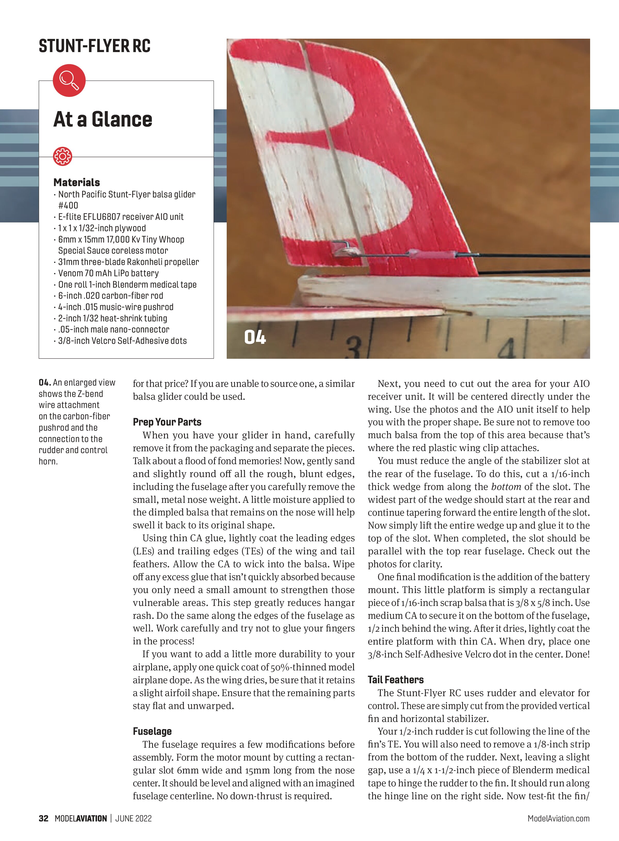
When you have your glider in hand, carefully remove it from the packaging and separate the pieces. Talk about a flood of fond memories! Now, gently sand and slightly round off all the rough, blunt edges, including the fuselage after you carefully remove the small, metal nose weight. A little moisture applied to the dimpled balsa that remains on the nose will help swell it back to its original shape.
Using thin CA glue, lightly coat the leading edges (LEs) and trailing edges (TEs) of the wing and tail feathers. Allow the CA to wick into the balsa. Wipe off any excess glue that isn’t quickly absorbed because you only need a small amount to strengthen those vulnerable areas. This step greatly reduces hangar rash. Do the same along the edges of the fuselage as well. Work carefully and try not to glue your fingers in the process!
If you want to add a little more durability to your airplane, apply one quick coat of 50%-thinned model airplane dope. As the wing dries, be sure that it retains a slight airfoil shape. Ensure that the remaining parts stay flat and unwarped.
Fuselage
The fuselage requires a few modifications before assembly. Form the motor mount by cutting a rectangular slot 6mm wide and 15mm long from the nose center. It should be level and aligned with an imagined fuselage centerline. No down-thrust is required.
Next, you need to cut out the area for your AIO receiver unit. It will be centered directly under the wing. Use the photos and the AIO unit itself to help you with the proper shape. Be sure not to remove too much balsa from the top of this area because that’s where the red plastic wing clip attaches.
You must reduce the angle of the stabilizer slot at the rear of the fuselage. To do this, cut a 1/16-inch thick wedge from along the bottom of the slot. The widest part of the wedge should start at the rear and continue tapering forward the entire length of the slot. Now simply lift the entire wedge up and glue it to the top of the slot. When completed, the slot should be parallel with the top rear fuselage. Check out the photos for clarity.
One final modification is the addition of the battery mount. This little platform is simply a rectangular piece of 1/16-inch scrap balsa that is 3/8 x 5/8 inch. Use medium CA to secure it on the bottom of the fuselage, 1/2 inch behind the wing. After it dries, lightly coat the entire platform with thin CA. When dry, place one 3/8-inch Self-Adhesive Velcro dot in the center. Done!
Tail Feathers
The Stunt-Flyer RC uses rudder and elevator for control. These are simply cut from the provided vertical fin and horizontal stabilizer.
Your 1/2-inch rudder is cut following the line of the fin’s TE. You will also need to remove a 1/8-inch strip from the bottom of the rudder. Next, leaving a slight gap, use a 1/4 x 1-1/2-inch piece of Blenderm medical tape to hinge the rudder to the fin. It should run along the hinge line on the right side. Now test-fit the fin/rudder assembly into its provided slot. Check the rudder for freedom of movement and when you’re satisfied, use thin CA to glue the fin into place.


The 3/8-inch elevator is similarly cut from the horizontal stabilizer’s TE. Again, leaving a slight gap, use two 1/4 x 2-inch pieces of Blenderm tape to hinge the elevator to the stabilizer. The T hinges should be secured on top with a 1/2-inch gap between. Now slide the stabilizer into its slot but only to the hinge line. Check for proper alignment and free elevator movement. When satisfied, use thin CA to secure it in place.
Control Horns
The elevator and rudder control horns are made of 1/32 plywood. They are 3/8 inch tall, 3/16 inch wide at the base, and 1/8 inch wide at the tip. Round both tips with sandpaper then drill a .015 hole in the center of the rounded areas.
The bottom of the horns should be cut so that they angle slightly forward over the hinge lines. Finally, use medium CA to carefully glue the rudder horn to the right side of the rudder, 1/4 inch up from the fuselage. Glue the elevator horn to the top of the elevator, 1/4 inch to the left of the fuselage.
Modified Receiver Unit
The E-flite EFLU6807 AIO receiver unit is the heart and soul of your little Stunt-Flyer. This amazing piece of micro technology is only the size of a US postage stamp, yet it incorporates a receiver, ESC, and two linear servos!
Before the AIO unit is installed, you must choose one of two small modifications. As shown in the construction photos, one option is to replace the existing motor leads (wires) with a .05-inch male nano-connector. This requires a soldering iron with a pencil tip and a fairly steady hand.
There are two tiny soldering points, but it is easily doable. By adding this nano-connector, the motor’s pre-terminated leads can simply be plugged in. If needed, the motor rotation can then be reversed by simply unplugging the leads and turning them over, and plugging them back in. This option also saves some weight.
The second option is to leave the AIO motor leads (wires) attached to the circuit board and simply connecting it to the motor’s pre-terminated leads. This is initially easier, but the direction of the motor rotation is not easily reversed because the plug only fits one way. Reversing the motor rotation requires that one set of leads be removed and reversed within its tiny, terminated end. It can be done, but there is slightly more weight and wire to deal with.
Receiver Check and Install
With the motor leads connected, power up the AIO receiver unit and bind it to your transmitter. After it is bound, check for the proper motor rotation (clockwise when viewed from the rear). Should you need to reverse the direction of rotation, that is best done before the components are installed.
Now check for the proper servo movement. With the servo gears facing away from you, right rudder input should move the right linear servo arm forward. Similarly, up-elevator input should move the left linear servo arm forward. If necessary, use the reverse

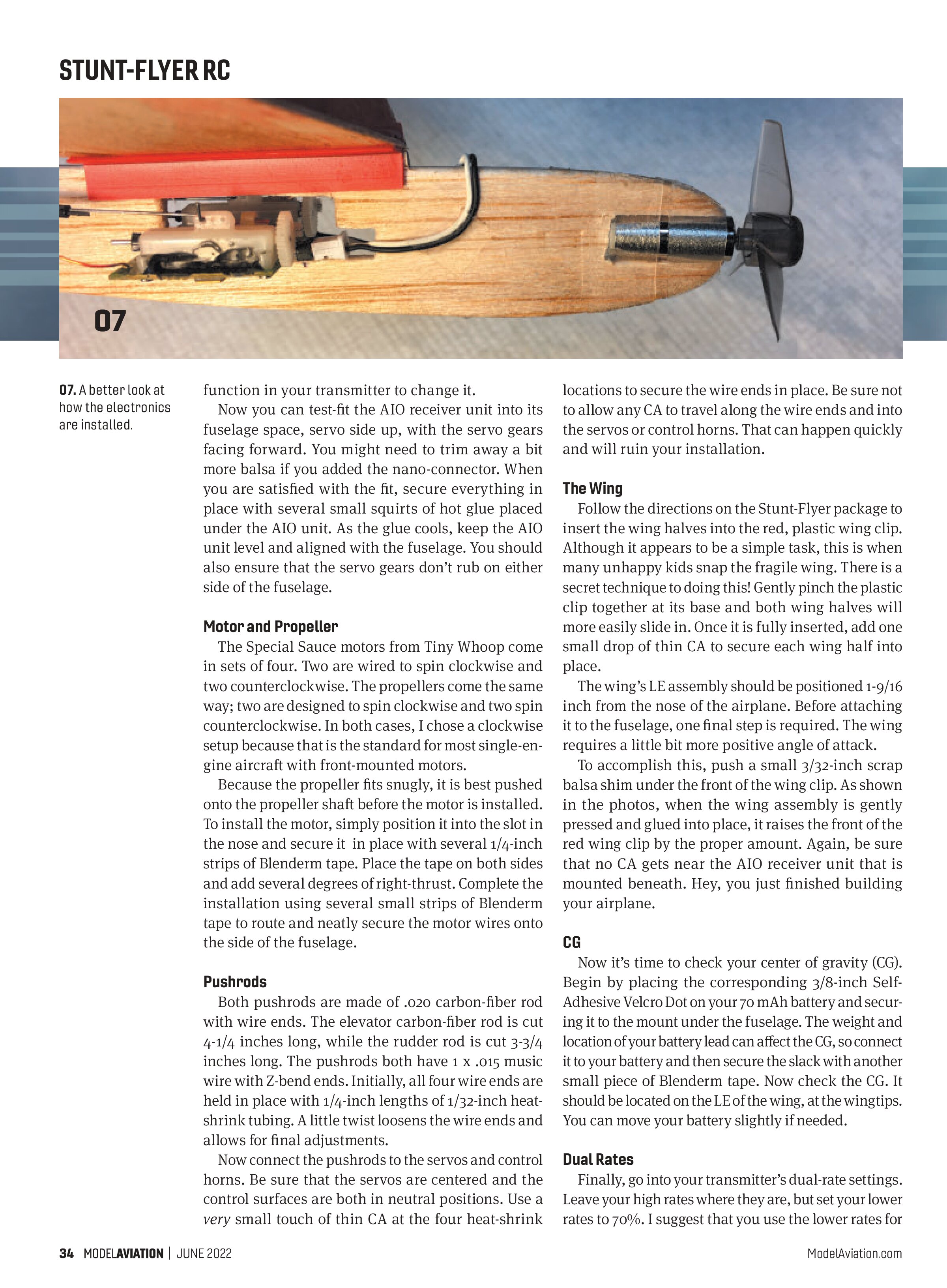
07. A better look at how the electronics are installed.
function in your transmitter to change it.
Now you can test-fit the AIO receiver unit into its fuselage space, servo side up, with the servo gears facing forward. You might need to trim away a bit more balsa if you added the nano-connector. When you are satisfied with the fit, secure everything in place with several small squirts of hot glue placed under the AIO unit. As the glue cools, keep the AIO unit level and aligned with the fuselage. You should also ensure that the servo gears don’t rub on either side of the fuselage.
Motor and Propeller
The Special Sauce motors from Tiny Whoop come in sets of four. Two are wired to spin clockwise and two counterclockwise. The propellers come the same way; two are designed to spin clockwise and two spin counterclockwise. In both cases, I chose a clockwise setup because that is the standard for most single-engine aircraft with front-mounted motors.
Because the propeller fits snugly, it is best pushed onto the propeller shaft before the motor is installed. To install the motor, simply position it into the slot in the nose and secure it in place with several 1/4-inch strips of Blenderm tape. Place the tape on both sides and add several degrees of right-thrust. Complete the installation using several small strips of Blenderm tape to route and neatly secure the motor wires onto the side of the fuselage.
Pushrods
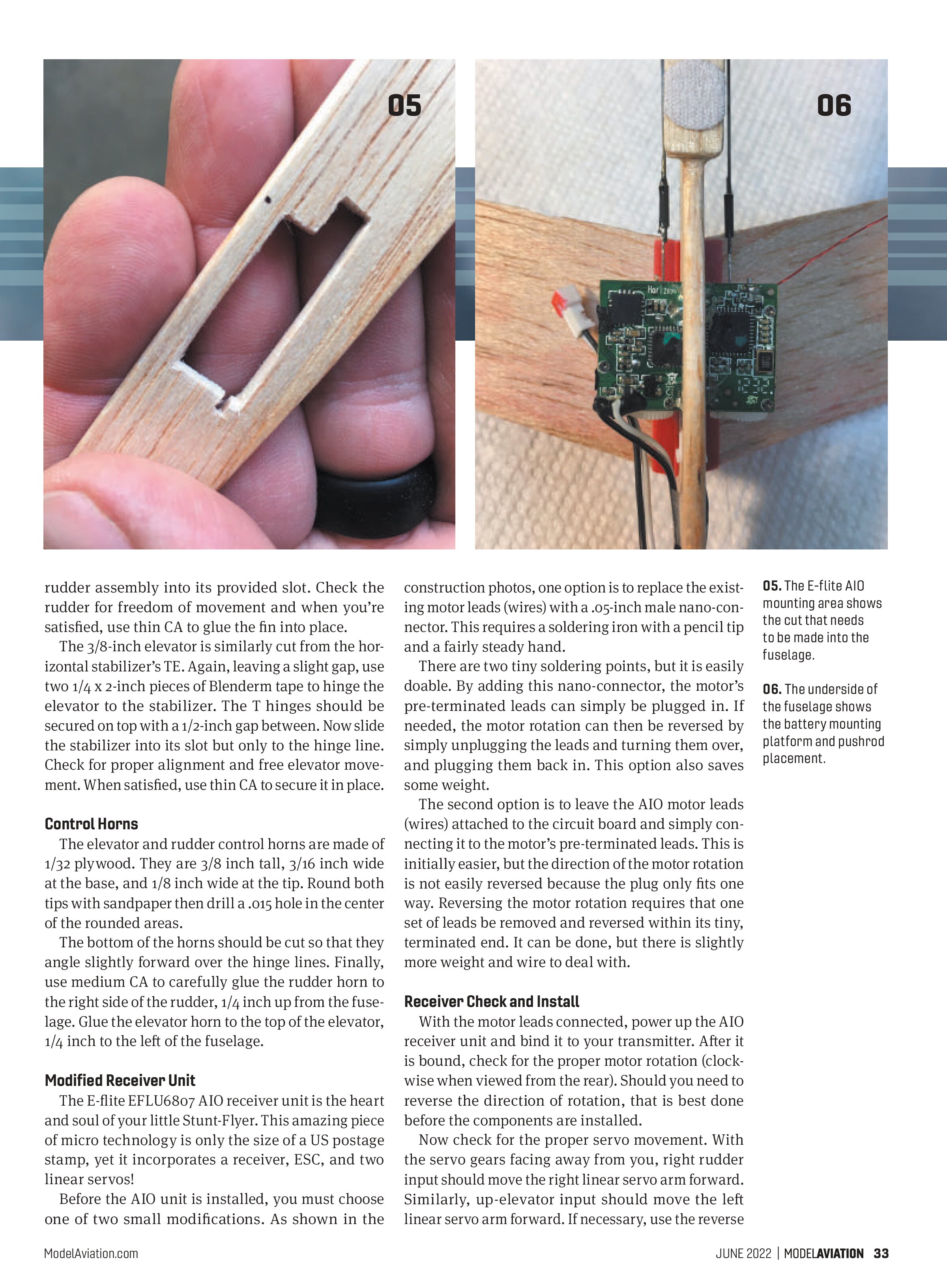
Both pushrods are made of .020 carbon-fiber rod with wire ends. The elevator carbon-fiber rod is cut 4-1/4 inches long, while the rudder rod is cut 3-3/4 inches long. The pushrods both have 1 x .015 music wire with Z-bend ends. Initially, all four wire ends are held in place with 1/4-inch lengths of 1/32-inch heat-shrink tubing. A little twist loosens the wire ends and allows for final adjustments.
Now connect the pushrods to the servos and control horns. Be sure that the servos are centered and the control surfaces are both in neutral positions. Use a very small touch of thin CA at the four heat-shrink locations to secure the wire ends in place. Be sure not to allow any CA to travel along the wire ends and into the servos or control horns. That can happen quickly and will ruin your installation.
The Wing
Follow the directions on the Stunt-Flyer package to insert the wing halves into the red, plastic wing clip. Although it appears to be a simple task, this is when many unhappy kids snap the fragile wing. There is a secret technique to doing this! Gently pinch the plastic clip together at its base and both wing halves will more easily slide in. Once it is fully inserted, add one small drop of thin CA to secure each wing half into place.
The wing’s LE assembly should be positioned 1-9/16 inch from the nose of the airplane. Before attaching it to the fuselage, one final step is required. The wing requires a little bit more positive angle of attack.
To accomplish this, push a small 3/32-inch scrap balsa shim under the front of the wing clip. As shown in the photos, when the wing assembly is gently pressed and glued into place, it raises the front of the red wing clip by the proper amount. Again, be sure that no CA gets near the AIO receiver unit that is mounted beneath. Hey, you just finished building your airplane.
CG
Now it’s time to check your center of gravity (CG). Begin by placing the corresponding 3/8-inch Self-Adhesive Velcro Dot on your 70 mAh battery and securing it to the mount under the fuselage. The weight and location of your battery lead can affect the CG, so connect it to your battery and then secure the slack with another small piece of Blenderm tape. Now check the CG. It should be located on the LE of the wing, at the wingtips. You can move your battery slightly if needed.
Dual Rates
Finally, go into your transmitter’s dual-rate settings. Leave your high rates where they are, but set your lower rates to 70%. I suggest that you use the lower rates for


your first flight. Don’t worry about your rudder and elevator throw amounts. For now, just take what you get. Further adjustments can be made later if you wish.
Time to Fly!
Okay, the day of your maiden flight has arrived. You will initially want to fly your Stunt-Flyer RC over grass. Actually, because there is no landing gear, I recommend always flying over grass. Should the unthinkable occur, grass is your friend. Just remember to chop the throttle before impact and hang on. In most cases, your Stunt-Flyer will simply bounce off of the grass without any damage.
At your flying site, conduct one final system check. If all works properly, call the tower and inform them that you are ready for takeoff. When cleared for departure, face into the wind and give your Stunt-Flyer RC full throttle.
Now briskly launch your little airplane slightly nose up. Allow it to gently climb out and when it’s at a comfortable height, throttle back and trim it for level flight. With all of the dihedral, you will find it’s stable in flight.
Next, try a few shallow turns. Only a little control input is needed—don’t overcontrol it. Less is more with your Stunt-Flyer RC. Remember to keep your control movements smooth. When you start feeling more comfortable, try a few loops, rolls, and spins. It’s loads of fun—after all, it is a Stunt-Flyer.
When the motor starts to pulse, that’s your signal that it’s time to head back to the airport. The Stunt-Flyer RC is not much of a floater, so you might need a little power to help carry you in. When it’s a few feet off the ground, cut the power, gently flare, and
you are down. On grass, there is no rollout, so don’t worry about the little battery that’s attached beneath.
In the Pilot’s Lounge
Congratulations! I hope you enjoyed your flight back through time. The Stunt-Flyer RC really has no bad habits. The more you fly your nostalgic, little micro flyer, the more fun it becomes. Your flying buddies might want a Stunt-Flyer RC for themselves, so be prepared to answer a few of their questions. After all, we were all kids once, right?
Until next time, stay safe and well. I hope that all of your flights are epic, and I wish you many happy landings.
SOURCES:
E-flite
(800) 338-4639
www.horizonhobby.com/e-flite-1
Rakonheli
rakonheli@rakonheli.com
www.rakonheli.com
Venom RC Products
www.towerhobbies.com
RC-Connectors.com
www.rc-connectors.com
Spektrum
(800) 338-4639
www.spektrumrc.com
Tiny Whoop
orders@tinywhoop.com
www.tinywhoop.com