UNRAVELING ELECTRIC AIRPLANE MYTHS, PART TWO
By Terry Dunn | terrydunn74@gmail.com

IN THE FEBRUARY 2022 edition of this column, I discussed some of my airplane models that use older, brushed motors rather than modern, brushless motors. I have received a tremendous volume of feedback from readers who also continue to use and love brushed motors in their models.
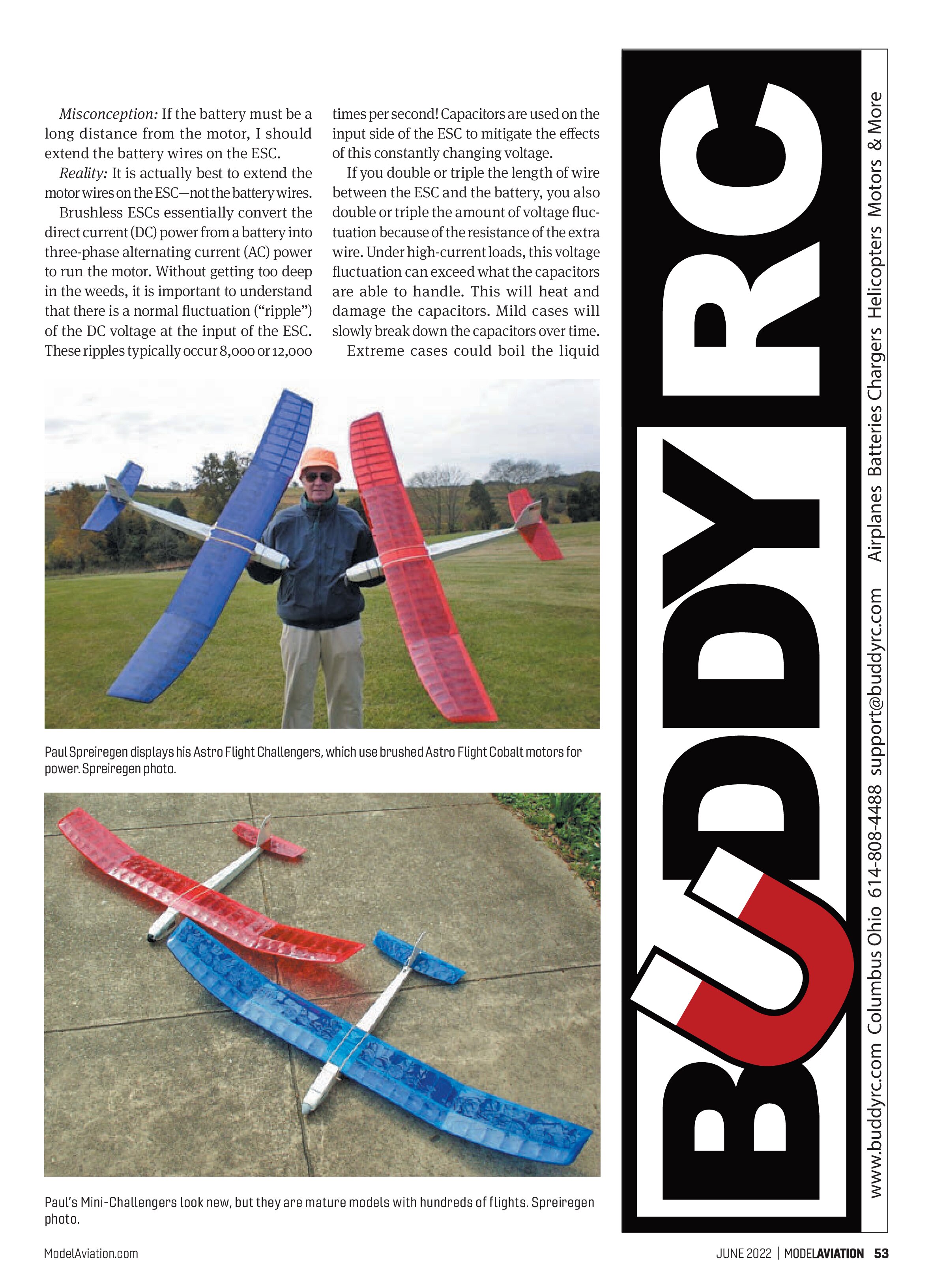
One noteworthy email was sent by Paul Spreiregen. Among his varied fleet of models, Paul has four airplanes that were built from Astro Flight kits and are also powered by Astro Flight brushed motors. He explained:
“The two airplanes in the photo are Astro Flight Mini-Challengers, both with Astro Flight Cobalt 035 direct-drive motors. I also have their big brothers, two full-size Challengers, with geared Cobalt 05 motors. The Mini-Challengers have roughly 60-inch wingspans, while the full-size Challengers are 72 inches. All are superb fliers. The four airplanes together have logged approximately 600 flights. Two are nearly 25 years old, and two are more than 15 years old.”
I think you will agree that Paul’s models have aged splendidly! It is great to know that they are still performing well with brushed motors and providing enjoyment. My thanks to Paul and everyone else who took the time to share their stories and photos with me. Keep them coming!
Electric Enigma Continued
In my April 2022 column, I teamed up with Lucien Miller of Innov8tive Designs to dispel some common misconceptions about electric power systems. I will address a couple more topics this month.
Misconception: If the battery must be a long distance from the motor, I should extend the battery wires on the ESC.
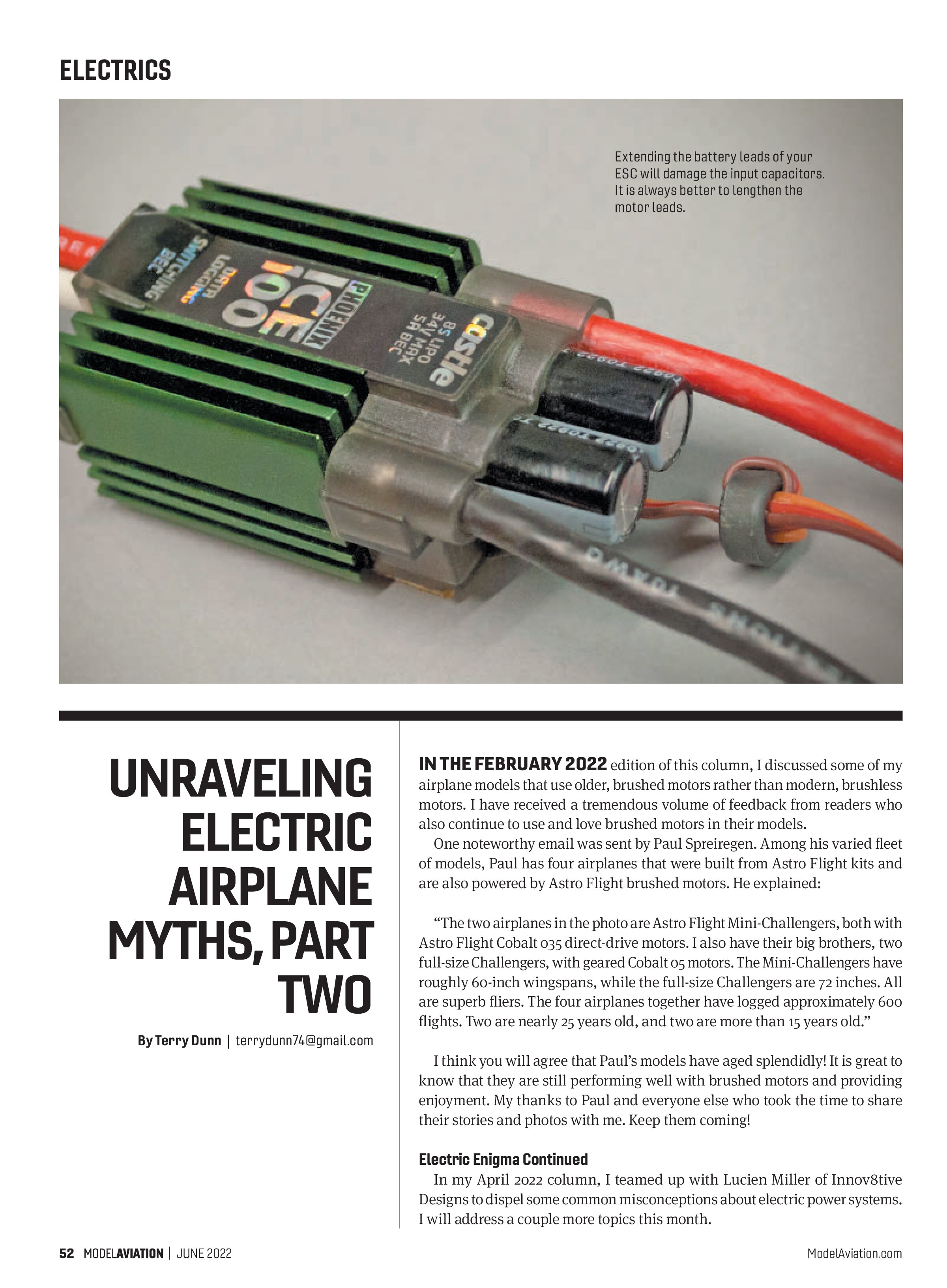
Reality: It is actually best to extend the motor wires on the ESC—not the battery wires. Brushless ESCs essentially convert the direct current (DC) power from a battery into three-phase alternating current (AC) power to run the motor. Without getting too deep in the weeds, it is important to understand that there is a normal fluctuation (“ripple”) of the DC voltage at the input of the ESC. These ripples typically occur 8,000 or 12,000 times per second! Capacitors are used on the input side of the ESC to mitigate the effects of this constantly changing voltage.
If you double or triple the length of wire between the ESC and the battery, you also double or triple the amount of voltage fluctuation because of the resistance of the extra wire. Under high-current loads, this voltage fluctuation can exceed what the capacitors are able to handle. This will heat and damage the capacitors. Mild cases will slowly break down the capacitors over time. Extreme cases could boil the liquid


electrolytes inside the capacitor, resulting in a rather spectacular flame and a bad day at the flying field.
The output side of the ESC is a three-phase AC, which is easily transmitted over long distances with no ill effects. For instance, the AC power used in houses often travels hundreds of miles before getting to a neighborhood. AC power is not affected by the distance traveled as DC power is, so it is always best to lengthen the motor wires of an ESC rather than the battery wires.
Power Struggle
Misconception: In multimotor airplanes with two or more ESCs, you must disable the BEC of all but one ESC.
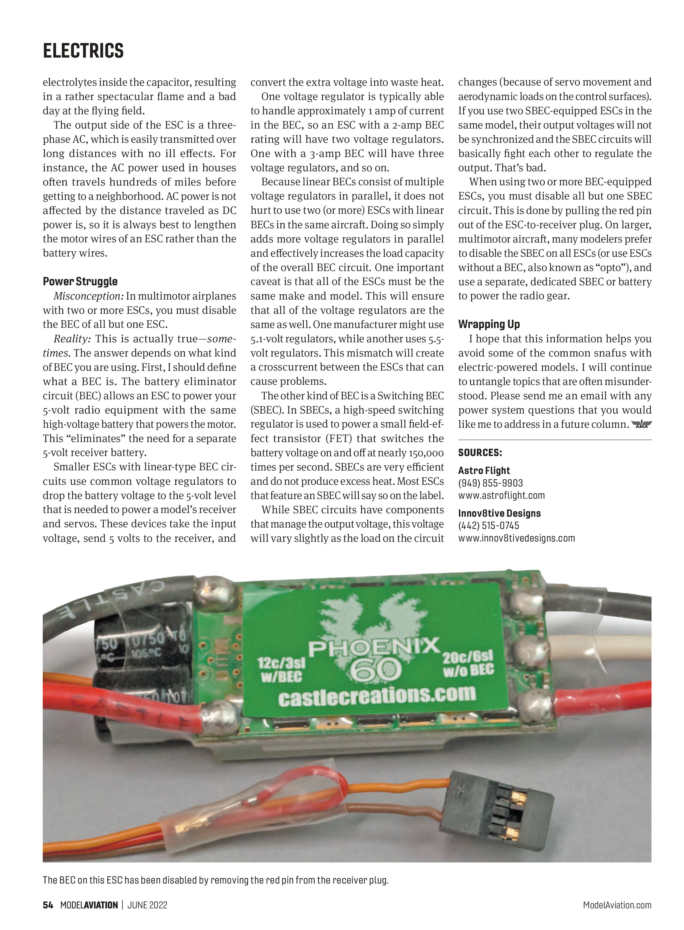
Reality: This is actually true—sometimes. The answer depends on what kind of BEC you are using. First, I should define what a BEC is. The battery eliminator circuit (BEC) allows an ESC to power your 5-volt radio equipment with the same high-voltage battery that powers the motor. This “eliminates” the need for a separate 5-volt receiver battery.
Smaller ESCs with linear-type BEC circuits use common voltage regulators to drop the battery voltage to the 5-volt level that is needed to power a model’s receiver and servos. These devices take the input voltage, send 5 volts to the receiver, and convert the extra voltage into waste heat.
One voltage regulator is typically able to handle approximately 1 amp of current in the BEC, so an ESC with a 2-amp BEC rating will have two voltage regulators. One with a 3-amp BEC will have three voltage regulators, and so on.
Because linear BECs consist of multiple voltage regulators in parallel, it does not hurt to use two (or more) ESCs with linear BECs in the same aircraft. Doing so simply adds more voltage regulators in parallel and effectively increases the load capacity of the overall BEC circuit. One important caveat is that all of the ESCs must be the same make and model. This will ensure that all of the voltage regulators are the same as well. One manufacturer might use 5.1-volt regulators, while another uses 5.5-volt regulators. This mismatch will create a crosscurrent between the ESCs that can cause problems.
The other kind of BEC is a Switching BEC (SBEC). In SBECs, a high-speed switching regulator is used to power a small field-effect transistor (FET) that switches the battery voltage on and off at nearly 150,000 times per second. SBECs are very efficient and do not produce excess heat. Most ESCs that feature an SBEC will say so on the label.
While SBEC circuits have components that manage the output voltage, this voltage will vary slightly as the load on the circuit changes (because of servo movement and aerodynamic loads on the control surfaces). If you use two SBEC-equipped ESCs in the same model, their output voltages will not be synchronized and the SBEC circuits will basically fight each other to regulate the output. That’s bad.
When using two or more BEC-equipped ESCs, you must disable all but one SBEC circuit. This is done by pulling the red pin out of the ESC-to-receiver plug. On larger, multimotor aircraft, many modelers prefer to disable the SBEC on all ESCs (or use ESCs without a BEC, also known as “opto”), and use a separate, dedicated SBEC or battery to power the radio gear.
Wrapping Up
I hope that this information helps you avoid some of the common snafus with electric-powered models. I will continue to untangle topics that are often misunderstood. Please send me an email with any power system questions that you would like me to address in a future column.

SOURCES:
Astro Flight
(949) 855-9903
www.astroflight.com
Innov8tive Designs
(442) 515-0745
www.innov8tivedesigns.com