FREE FLIGHT DURATION

IS YOUR WING LONG ENOUGH?
By Louis Joyner | joynerduration@gmail.com
IF YOU FLY ONE of the wingspan-limited events, such as P-30 or E-36, you must make sure that the model’s wing is not too long. For other events, the wingspan is up to you. A few events limit the wing area or total wing and stabilizer area, so you need to check that the wing or wing/stabilizer combination are within the limit of the rules. For many Free Flight (FF) events, there are no limits on the wingspan or wing area.
How long should your model’s wing be? Why is it important? The answer is aspect ratio: the relationship of the wingspan to the average wing chord.
The aspect ratio of a FF wing has steadily increased throughout the years. Longer wings have dramatically increased a model’s performance. At the 2021 Nats, the Menanno brothers dominated the large AMA Gas events. Guy Menanno’s B Gas winner spanned 107 inches, with an aspect ratio of 25:1. The wing of his C Gas-winning model measured 110 inches from wingtip to wingtip, but the aspect ratio was only 15:1. (Remember, aspect ratio is the wingspan divided by the average chord, so a wider chord will reduce the aspect ratio.) Neal Menanno won D Gas with the longest wing of all, at 111 inches, with an aspect ratio of nearly 17:1.
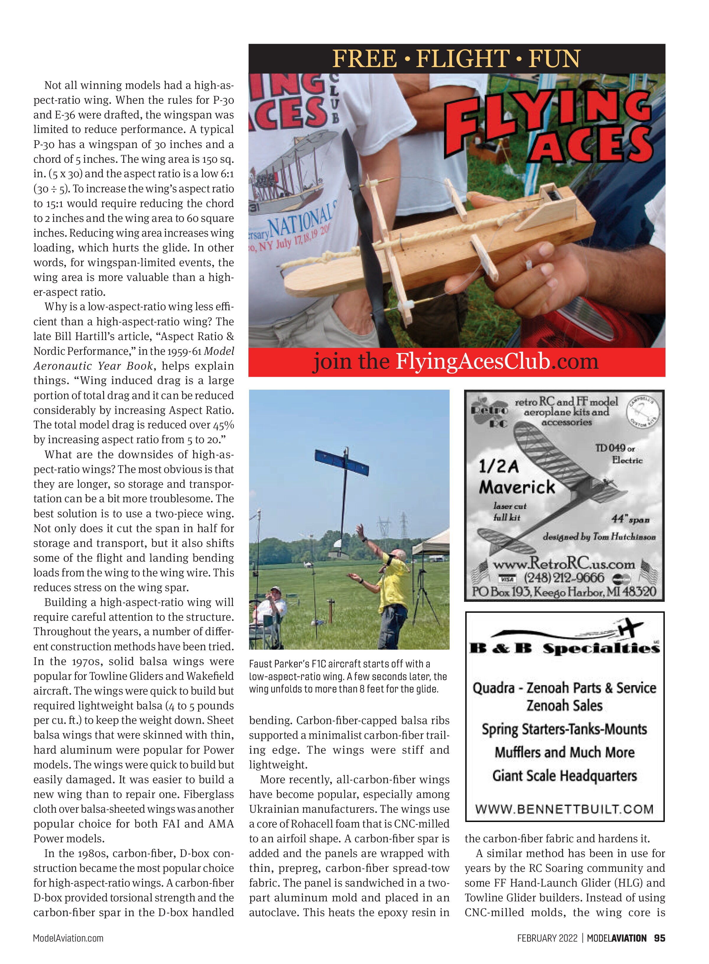
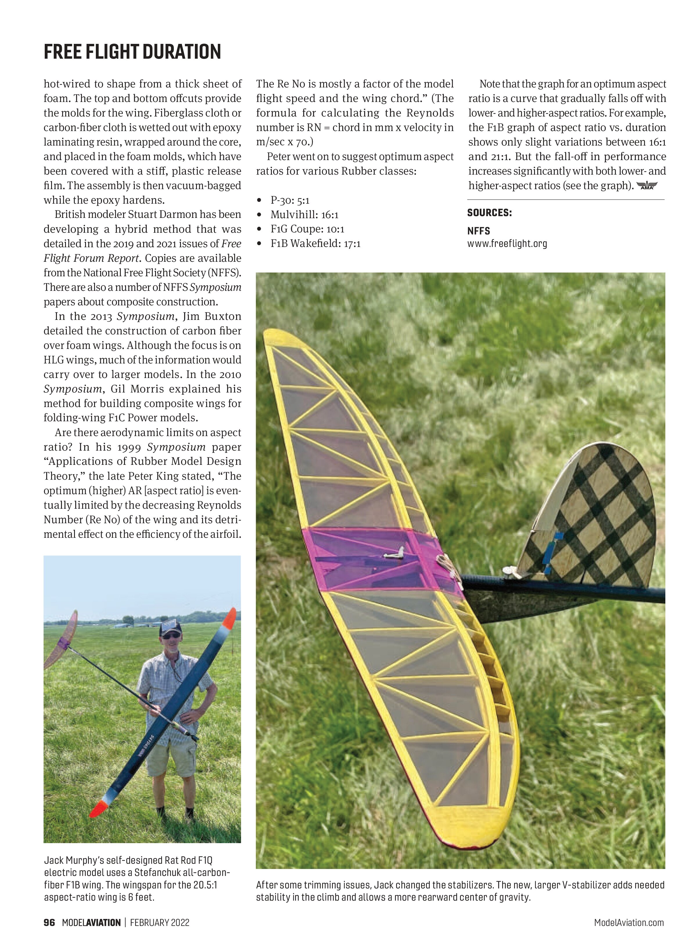
F1B winner Jerry Fitch was flying an Orca by Stepan Stefanchuk. The all-carbon-fiber wing had a wingspan of 6 feet, with an aspect ratio of 20.5:1. Faust Parker’s winning F1C model had one of the lowest aspect ratios on the field. At launch, the aspect ratio was slightly less than 7:1. A few seconds later, the engine shut off, the model bunted over from vertical to horizontal, and the six-panel wing unfolded for the glide. The opened wingspan was 97 inches, with an aspect ratio of approximately 18:1. It was among the highest.
Not all winning models had a high-aspect-ratio wing. When the rules for P-30 and E-36 were drafted, the wingspan was limited to reduce performance. A typical P-30 has a wingspan of 30 inches and a chord of 5 inches. The wing area is 150 sq. in. (5 x 30) and the aspect ratio is a low 6:1 (30 ÷ 5). To increase the wing’s aspect ratio to 15:1 would require reducing the chord to 2 inches and the wing area to 60 square inches. Reducing wing area increases wing loading, which hurts the glide. In other words, for wingspan-limited events, the wing area is more valuable than a higher-aspect-ratio.
Why is a low-aspect-ratio wing less efficient than a high-aspect-ratio wing? The late Bill Hartill’s article, “Aspect Ratio & Nordic Performance,” in the 1959-61 Model Aeronautic Year Book, helps explain things. “Wing induced drag is a large portion of total drag and it can be reduced considerably by increasing Aspect Ratio. The total model drag is reduced over 45% by increasing aspect ratio from 5 to 20.”
What are the downsides of high-aspect-ratio wings? The most obvious is that they are longer, so storage and transportation can be a bit more troublesome. The best solution is to use a two-piece wing. Not only does it cut the span in half for storage and transport, but it also shifts some of the flight and landing bending loads from the wing to the wing wire. This reduces stress on the wing spar.

Building a high-aspect-ratio wing will require careful attention to the structure. Throughout the years, a number of different construction methods have been tried. In the 1970s, solid balsa wings were popular for Towline Gliders and Wakefield aircraft. The wings were quick to build but required lightweight balsa (4 to 5 pounds per cu. ft.) to keep the weight down. Sheet balsa wings that were skinned with thin, hard aluminum were popular for Power models. The wings were quick to build but easily damaged. It was easier to build a new wing than to repair one. Fiberglass cloth over balsa-sheeted wings was another popular choice for both FAI and AMA Power models.
In the 1980s, carbon-fiber, D-box construction became the most popular choice for high-aspect-ratio wings. A carbon-fiber D-box provided torsional strength and the carbon-fiber spar in the D-box handled bending. Carbon-fiber-capped balsa ribs supported a minimalist carbon-fiber trailing edge. The wings were stiff and lightweight.
More recently, all-carbon-fiber wings have become popular, especially among Ukrainian manufacturers. The wings use a core of Rohacell foam that is CNC-milled to an airfoil shape. A carbon-fiber spar is added and the panels are wrapped with thin, prepreg, carbon-fiber spread-tow fabric. The panel is sandwiched in a two-part aluminum mold and placed in an autoclave. This heats the epoxy resin in the carbon-fiber fabric and hardens it.
A similar method has been in use for years by the RC Soaring community and some FF Hand-Launch Glider (HLG) and Towline Glider builders. Instead of using CNC-milled molds, the wing core is
hot-wired to shape from a thick sheet of foam. The top and bottom offcuts provide the molds for the wing. Fiberglass cloth or carbon-fiber cloth is wetted out with epoxy laminating resin, wrapped around the core, and placed in the foam molds, which have been covered with a stiff, plastic release film. The assembly is then vacuum-bagged while the epoxy hardens.
British modeler Stuart Darmon has been developing a hybrid method that was detailed in the 2019 and 2021 issues of Free Flight Forum Report. Copies are available from the National Free Flight Society (NFFS). There are also a number of NFFS Symposium papers about composite construction.
In the 2013 Symposium, Jim Buxton detailed the construction of carbon fiber over foam wings. Although the focus is on HLG wings, much of the information would carry over to larger models. In the 2010 Symposium, Gil Morris explained his method for building composite wings for folding-wing F1C Power models.
Are there aerodynamic limits on aspect ratio? In his 1999 Symposium paper “Applications of Rubber Model Design Theory,” the late Peter King stated, “The optimum (higher) AR [aspect ratio] is eventually limited by the decreasing Reynolds Number (Re No) of the wing and its detrimental effect on the efficiency of the airfoil.

The Re No is mostly a factor of the model flight speed and the wing chord.” (The formula for calculating the Reynolds number is RN = chord in mm x velocity in m/sec x 70.)
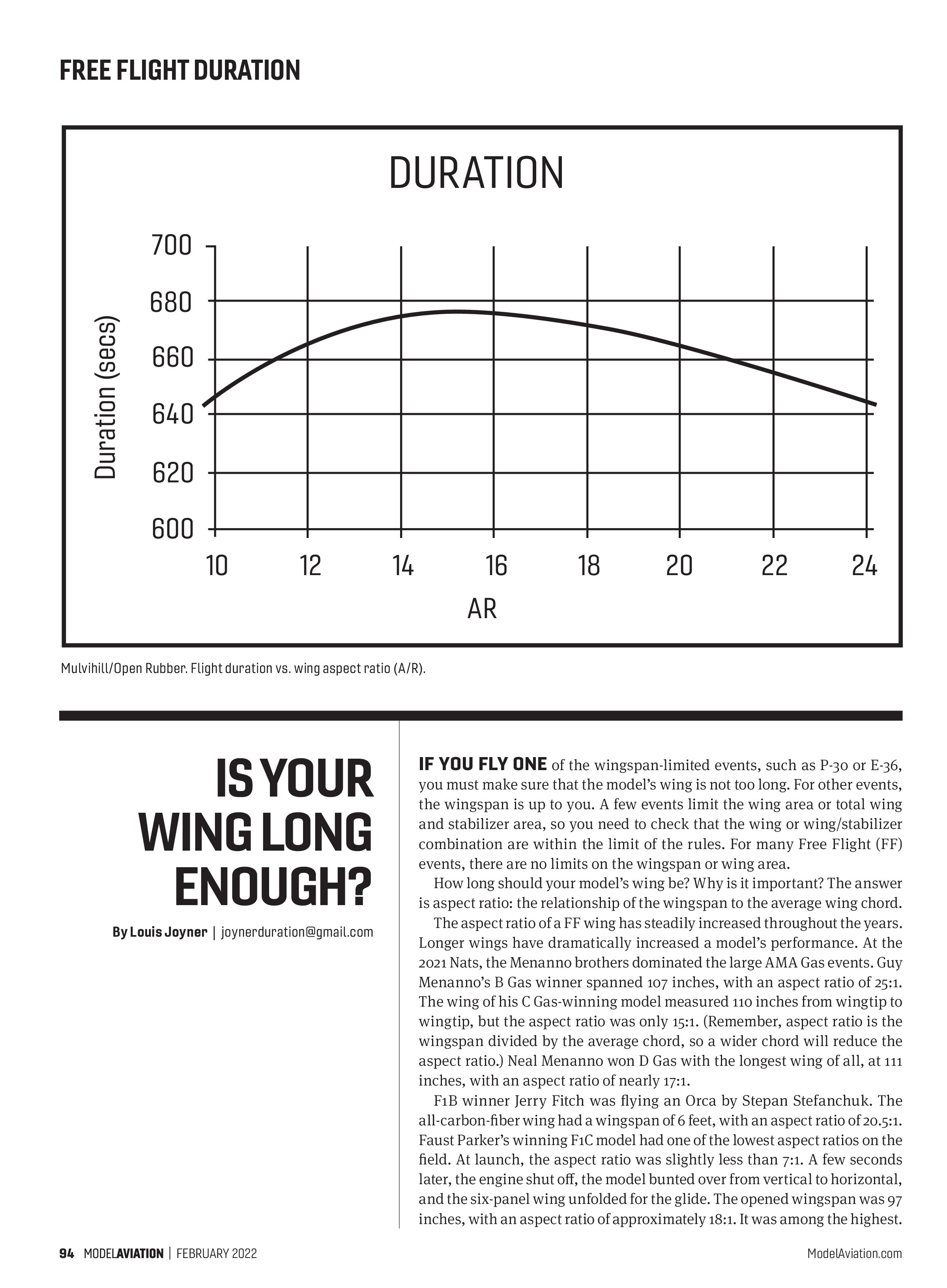
Peter went on to suggest optimum aspect ratios for various Rubber classes:
- P-30: 5:1
- Mulvihill: 16:1
- F1G Coupe: 10:1
- F1B Wakefield: 17:1
Note that the graph for an optimum aspect ratio is a curve that gradually falls off with lower- and higher-aspect ratios. For example, the F1B graph of aspect ratio vs. duration shows only slight variations between 16:1 and 21:1. But the fall-off in performance increases significantly with both lower- and higher-aspect ratios (see the graph).
SOURCES: