RC PYLON RACING
TDC AND HEAD
CLEARANCE
ON JETT 426
Q-500 ENGINES
By Tim Lampe | tim.lampe@hotmail.com
A WHILE AGO, Dub Jett asked me to write about how to measure the setup of the Jett 426 Quickie 500 (Q-500) Pylon Racing engine. For those who are unfamiliar with the term “setup” but who would still like to read along, it is a measurement of the distance between the top of the piston when it is at the top of its stroke (TDC or top dead center) and the top of the cylinder liner, and a measurement of the distance between the top of the piston (when at TDC) and the bottom of the head (or bottom of the head button for engines that have a removable one, such as the Jett 426).
These two figures very much determine how an engine should perform, but some inexperienced (and some experienced) Pylon Racing pilots are not certain of their engine’s setup, although it is the first thing you have to know when diagnosing potential engine issues. What’s your setup?
I am aware that experienced Pylon Racing pilots already have their own tools and methods for measuring engine setup, so this column is aimed toward beginner and intermediate pilots who might wish to know their engine setup simply for record-keeping purposes or to return their engine to the stock settings if, for any reason, they (or someone else) might have changed the setup.
If you purchased your engine new, directly from Jett Aerotech, you might not even want to open it up at all. In fact, this is what Dub prefers. If you then go to him with a question about your engine and he asks, “What’s the setup?” I suppose you would reply that it’s exactly as you received it and the diagnosis would proceed from there.
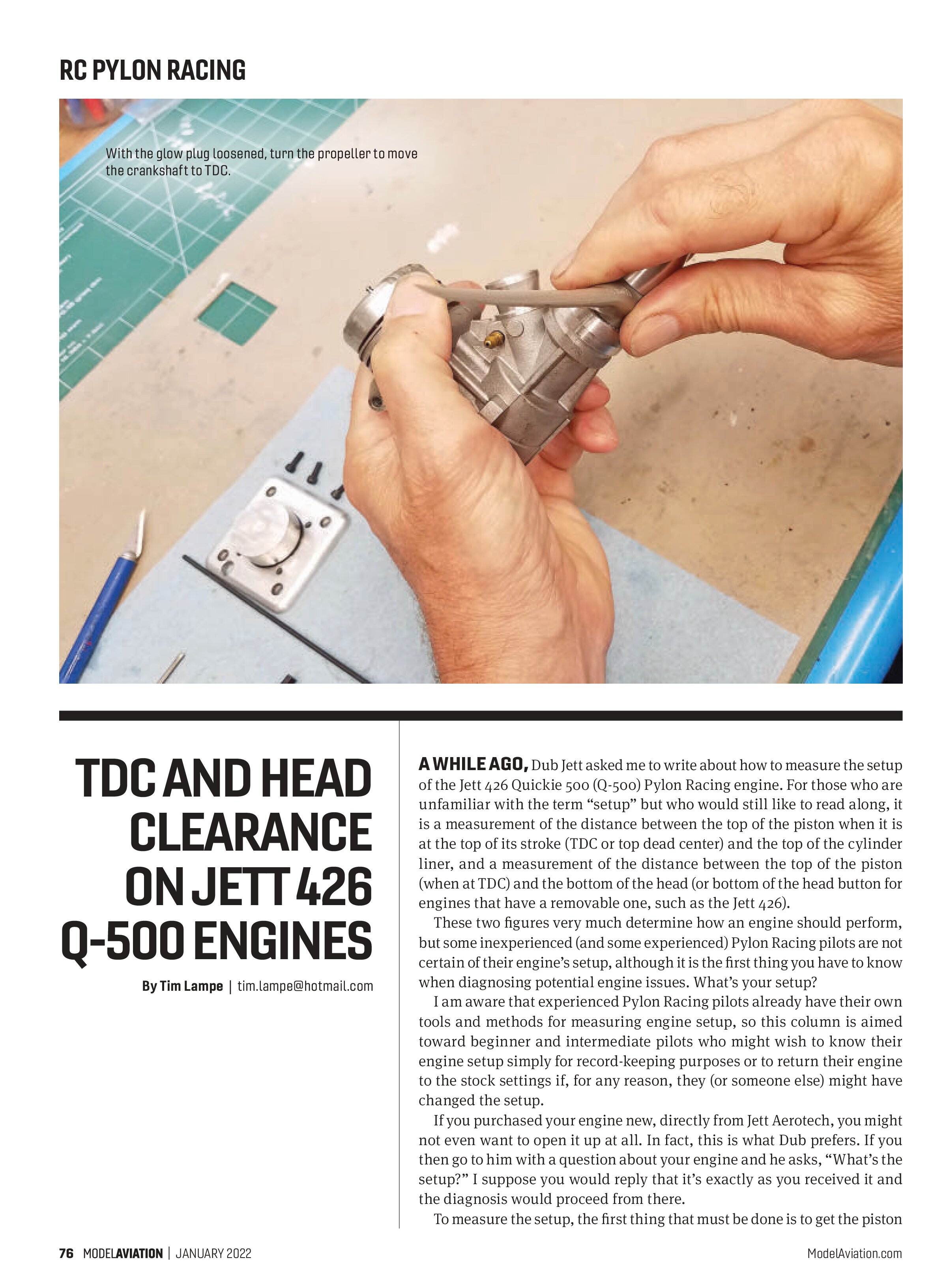
To measure the setup, the first thing that must be done is to get the piston to TDC. Loosen the glow plug and, with a propeller on the engine, turn the crankshaft until the piston seems to “freeze” at TDC. You will know it’s there (or as close as you can get it) when the propeller loosely rocks back and forth slightly.
It’s helpful to have some type of stand or mount to secure your engine while working on it. I use my engine test stand. (You might have to remove the backplate mount to fit on your stand.) Working in a clean environment, remove the head, head button, and any shims. “Zero” your dial depth gauge or mechanical depth micrometer, usually on a sheet of clean glass.
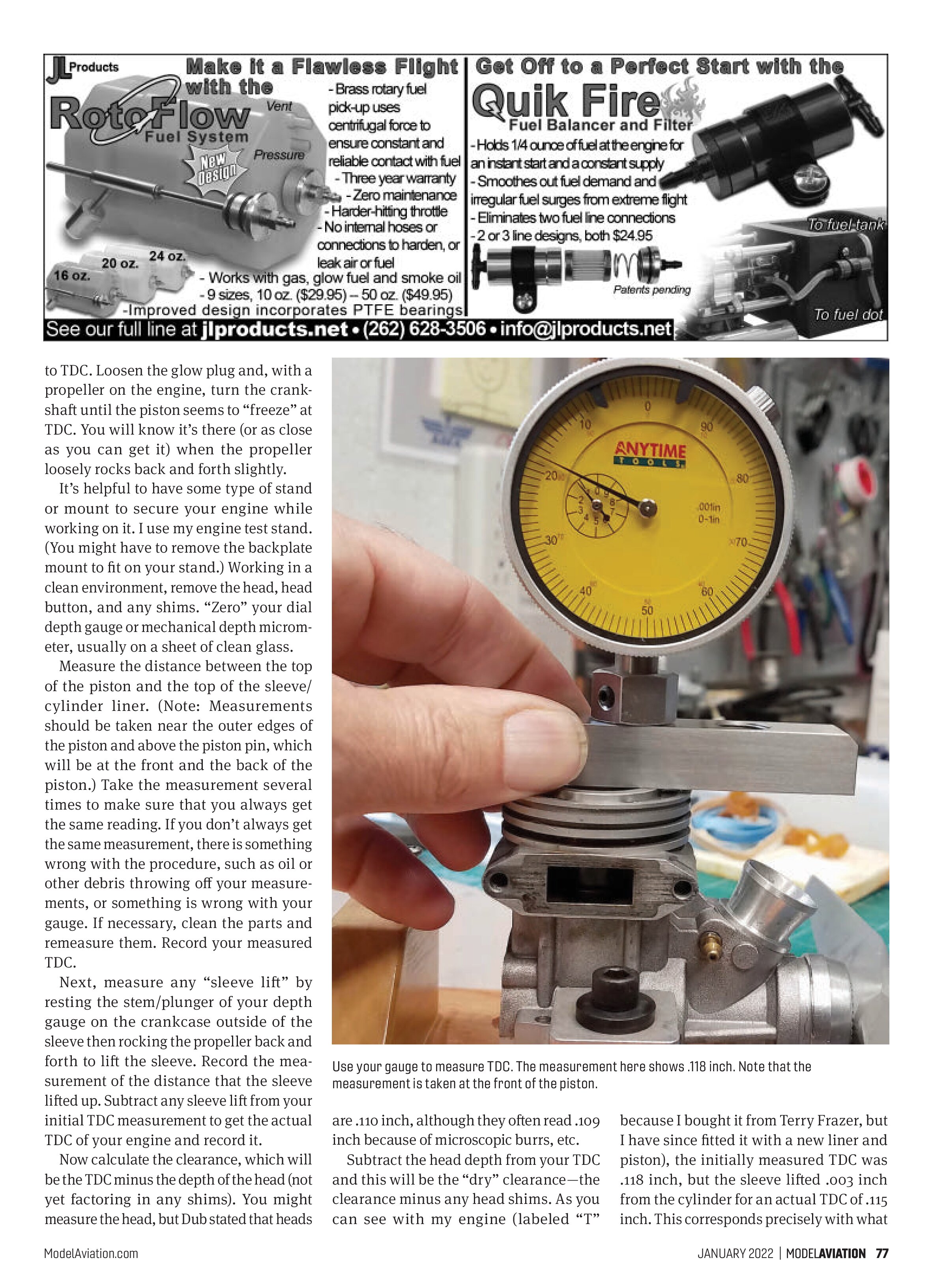
Measure the distance between the top of the piston and the top of the sleeve/cylinder liner. (Note: Measurements should be taken near the outer edges of the piston and above the piston pin, which will be at the front and the back of the piston.) Take the measurement several times to make sure that you always get the same reading. If you don’t always get the same measurement, there is something wrong with the procedure, such as oil or other debris throwing off your measurements, or something is wrong with your gauge. If necessary, clean the parts and remeasure them. Record your measured TDC.
Next, measure any “sleeve lift” by resting the stem/plunger of your depth gauge on the crankcase outside of the sleeve then rocking the propeller back and forth to lift the sleeve. Record the measurement of the distance that the sleeve lifted up. Subtract any sleeve lift from your initial TDC measurement to get the actual TDC of your engine and record it.
Now calculate the clearance, which will be the TDC minus the depth of the head (not yet factoring in any shims). You might measure the head, but Dub stated that heads are .110 inch, although they often read .109 inch because of microscopic burrs, etc.
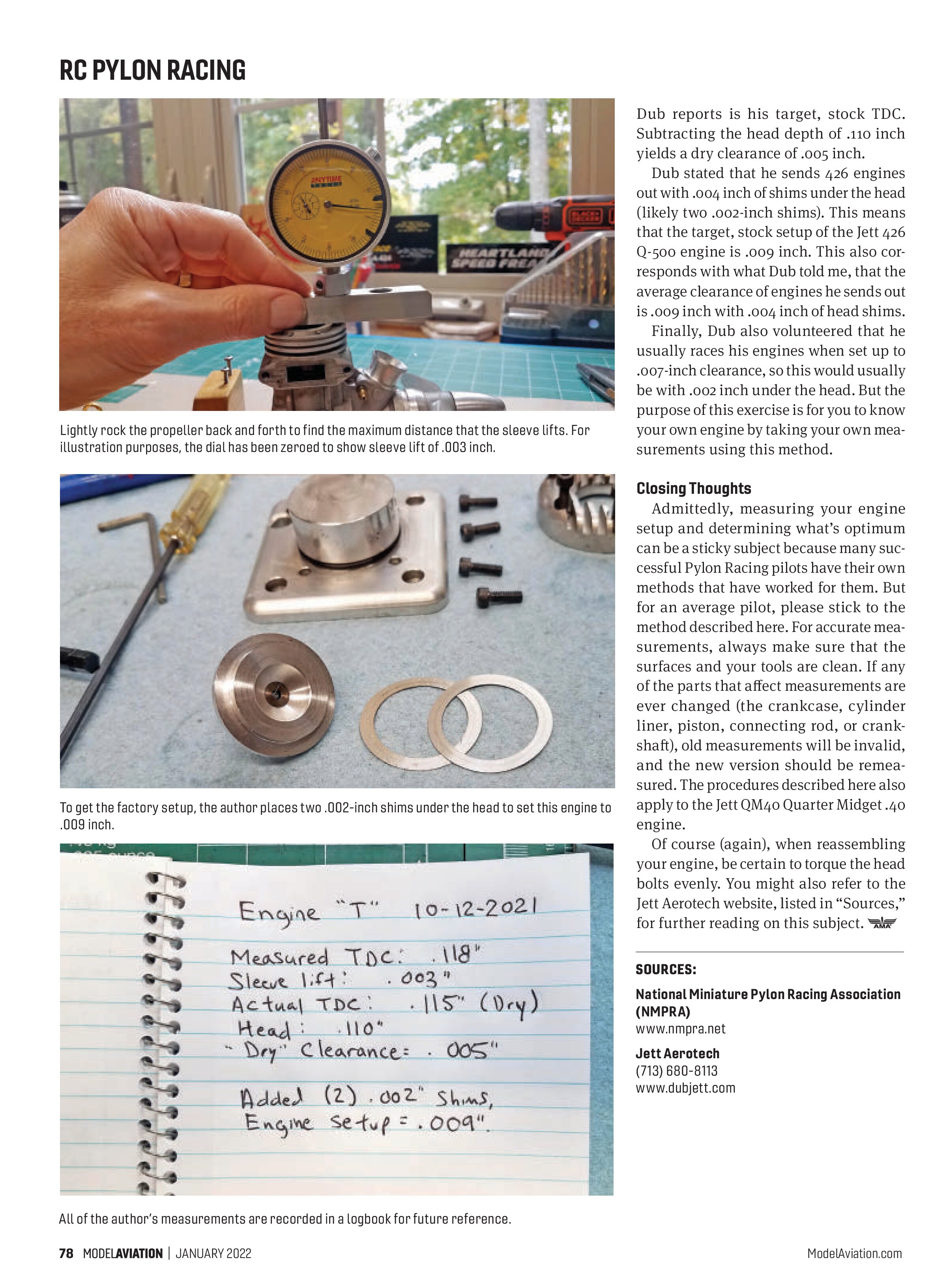
Subtract the head depth from your TDC and this will be the “dry” clearance—the clearance minus any head shims. As you can see with my engine (labeled “T” because I bought it from Terry Frazer, but I have since fitted it with a new liner and piston), the initially measured TDC was .118 inch, but the sleeve lifted .003 inch from the cylinder for an actual TDC of .115 inch. This corresponds precisely with what


Dub reports is his target, stock TDC. Subtracting the head depth of .110 inch yields a dry clearance of .005 inch.
Dub stated that he sends 426 engines out with .004 inch of shims under the head (likely two .002-inch shims). This means that the target, stock setup of the Jett 426 Q-500 engine is .009 inch. This also corresponds with what Dub told me, that the average clearance of engines he sends out is .009 inch with .004 inch of head shims.
Finally, Dub also volunteered that he usually races his engines when set up to .007-inch clearance, so this would usually be with .002 inch under the head. But the purpose of this exercise is for you to know your own engine by taking your own measurements using this method.
Closing Thoughts
Admittedly, measuring your engine setup and determining what’s optimum can be a sticky subject because many successful Pylon Racing pilots have their own methods that have worked for them. But for an average pilot, please stick to the method described here. For accurate measurements, always make sure that the surfaces and your tools are clean. If any of the parts that affect measurements are ever changed (the crankcase, cylinder liner, piston, connecting rod, or crankshaft), old measurements will be invalid, and the new version should be remeasured. The procedures described here also apply to the Jett QM40 Quarter Midget .40 engine.
Of course (again), when reassembling your engine, be certain to torque the head bolts evenly. You might also refer to the Jett Aerotech website, listed in “Sources,” for further reading on this subject.
SOURCES:
National Miniature Pylon Racing Association (NMPRA)
www.nmpra.net
Jett Aerotech
(713) 680-8113
www.udbjett.com