RC JETS

SETTING UP
GYROS
By Jim Hiller | jetmodeler@earthlink.net
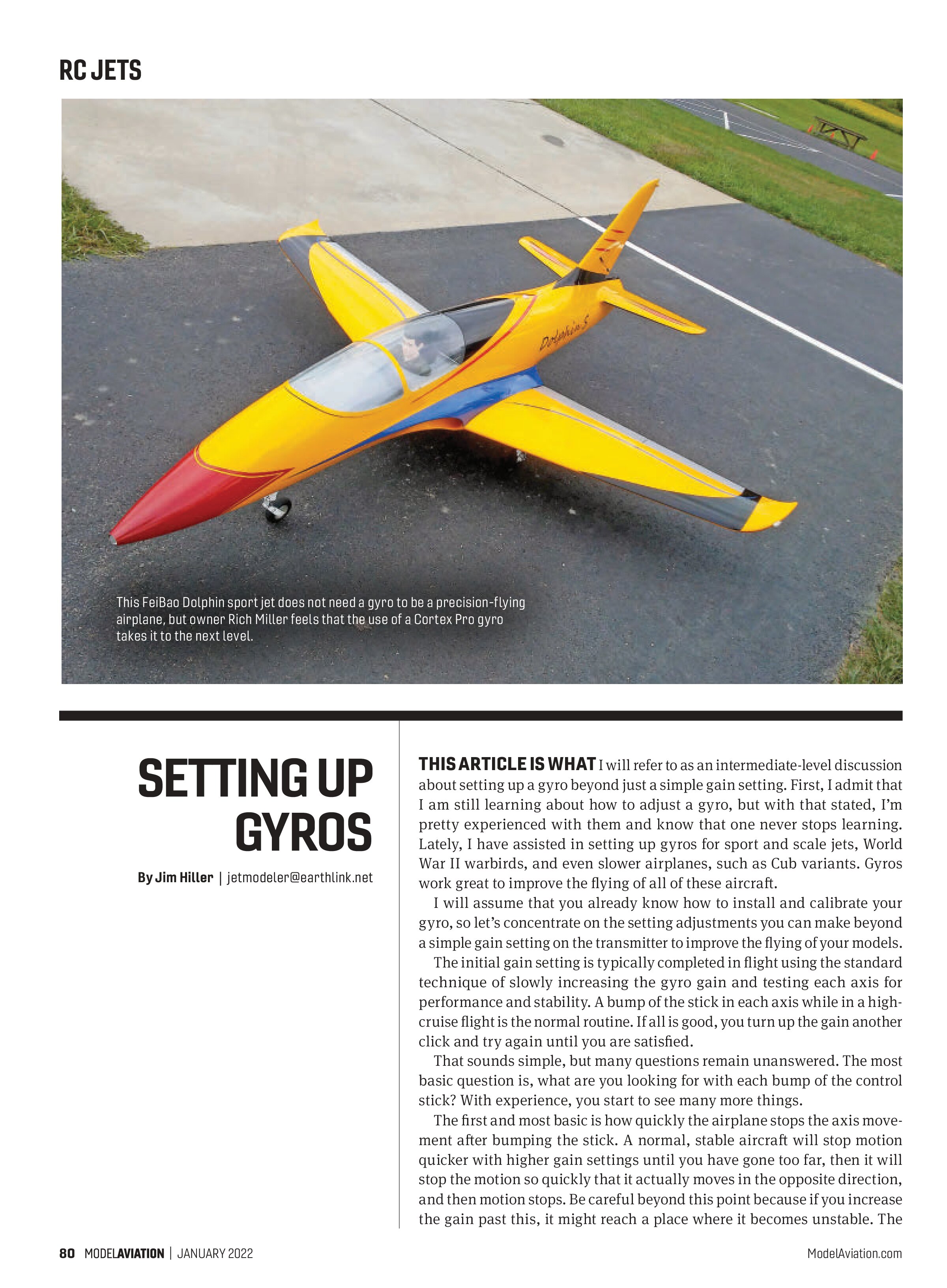
THIS ARTICLE IS WHAT I will refer to as an intermediate-level discussion about setting up a gyro beyond just a simple gain setting. First, I admit that I am still learning about how to adjust a gyro, but with that stated, I’m pretty experienced with them and know that one never stops learning. Lately, I have assisted in setting up gyros for sport and scale jets, World War II warbirds, and even slower airplanes, such as Cub variants. Gyros work great to improve the flying of all of these aircraft.
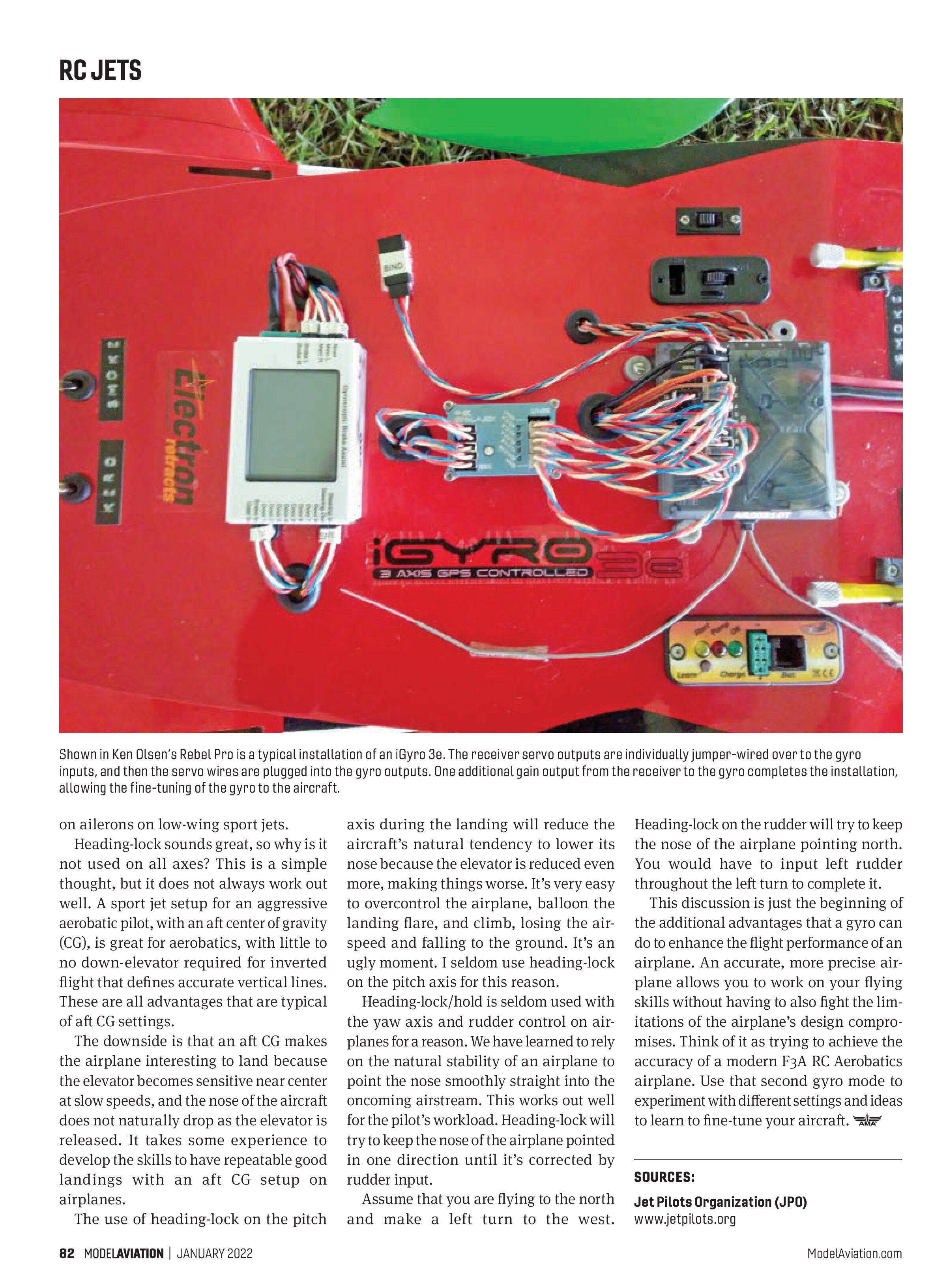
I will assume that you already know how to install and calibrate your gyro, so let’s concentrate on the setting adjustments you can make beyond a simple gain setting on the transmitter to improve the flying of your models.
The initial gain setting is typically completed in flight using the standard technique of slowly increasing the gyro gain and testing each axis for performance and stability. A bump of the stick in each axis while in a high-cruise flight is the normal routine. If all is good, you turn up the gain another click and try again until you are satisfied.
That sounds simple, but many questions remain unanswered. The most basic question is, what are you looking for with each bump of the control stick? With experience, you start to see many more things.
The first and most basic is how quickly the airplane stops the axis movement after bumping the stick. A normal, stable aircraft will stop motion quicker with higher gain settings until you have gone too far, then it will stop the motion so quickly that it actually moves in the opposite direction, and then motion stops. Be careful beyond this point because if you increase the gain past this, it might reach a place where it becomes unstable. The gyro will overcorrect so aggressively that it continues to correct back and forth—dynamically similar to flutter.
A good example of excessive gain is with the roll axis and aileron input. Bump the stick and you know the gain is too high if the airplane rolls back the other way with the release of the ailerons. This high gain is a popular setting on the ailerons because it overdefines the stops on point rolls, but let’s be honest—it does not make for smooth, precise flying when the airplane bounces back at each point of the roll.
Full-scale aerobatic pilots define their points in point rolls with a slight, momentary overtravel of the control stick to abruptly stop the roll motion, identifying a distinct stop. That is what gyros can also do—stop the roll inertia of the wing quickly to define a crisp stop to the roll.
The next level of setup requires individually programming the gain for each axis. This works well on scale jets, particularly 1940s and 1950s swept-wing jets. Those aircraft tend to have poor yaw stability, and a gyro can be effective, electronically enhancing yaw stability.
This is when you’ll appreciate the latest generation of transmitters. Many can do this with the right mix of transmitter and gyro to allow individual axis gain adjustment without requiring a laptop. A higher setting on the yaw access gain typically goes a long way to reduce the tail-wagging in turbulent air that is typical of these scale jets.
The next question is, should you use heading-lock or normal rate gain? This is a tough one because there is no clean answer. The servo speed, linkage geometry, airplane design, and your personal preference combine to answer this question. Don’t be afraid to try heading-lock on roll, but do it in a controlled trial method.
A gyro gain switch is normally programmed on the transmitter to allow the pilot to shut off the gyro in an emergency. A good example is when the gyro falls loose in the airplane and moves around, creating a nearly out-of-control situation.
I use a three-position switch for my gyro. I pull it toward me for normal gyro-mode setup, use the center position for off and zero gain, and away from me for any trial gyro-mode settings that I want to test. This is my standard. Others have their own setups, but this is not written in stone for all modelers.
I use this by taking advantage of the modes that are available in many of the higher-end gyros because they allow quite a bit of parameter customization in each mode. The two terms frequently thrown around are rate gyro corrections and heading-lock/hold-mode corrections.
In its simplest terms, normal-rate gyro setup resists unwanted motion by applying appropriate servo control travel to resist or stop the motion. Heading-lock, on the other hand, will not only correct unwanted motion but also try to retain/return to the current position without pilot input. The gyro modes typically allow each axis to be set up in its own desired rate or heading-lock setting. Heading-lock sounds great at first, but not so much in all cases of real-world flying.
Sport jets typically are of a low-wing design; all of the aircraft’s weight—turbine, radio, fuel, etc.—is above the wing. Add to that the need for little or no dihedral for minimal roll coupling in knife-edge flight. This design-compromise issue can create a lack of the feel that the roll axis is locked in.
A properly set-up gyro works well in rate mode to improve the precision and feel of the roll axis on these types of aircraft, and heading-lock on the ailerons will take it to the next level when it’s properly set up. You normally find heading-lock
on ailerons on low-wing sport jets.
Heading-lock sounds great, so why is it not used on all axes? This is a simple thought, but it does not always work out well. A sport jet setup for an aggressive aerobatic pilot, with an aft center of gravity (CG), is great for aerobatics, with little to no down-elevator required for inverted flight that defines accurate vertical lines. These are all advantages that are typical of aft CG settings.
The downside is that an aft CG makes the airplane interesting to land because the elevator becomes sensitive near center at slow speeds, and the nose of the aircraft does not naturally drop as the elevator is released. It takes some experience to develop the skills to have repeatable good landings with an aft CG setup on airplanes.
The use of heading-lock on the pitch axis during the landing will reduce the aircraft’s natural tendency to lower its nose because the elevator is reduced even more, making things worse. It’s very easy to overcontrol the airplane, balloon the landing flare, and climb, losing the airspeed and falling to the ground. It’s an ugly moment. I seldom use heading-lock on the pitch axis for this reason.
Heading-lock/hold is seldom used with the yaw axis and rudder control on airplanes for a reason. We have learned to rely on the natural stability of an airplane to point the nose smoothly straight into the oncoming airstream. This works out well for the pilot’s workload. Heading-lock will try to keep the nose of the airplane pointed in one direction until it’s corrected by rudder input.
Assume that you are flying to the north and make a left turn to the west. Heading-lock on the rudder will try to keep the nose of the airplane pointing north. You would have to input left rudder throughout the left turn to complete it.
This discussion is just the beginning of the additional advantages that a gyro can do to enhance the flight performance of an airplane. An accurate, more precise airplane allows you to work on your flying skills without having to also fight the limitations of the airplane’s design compromises. Think of it as trying to achieve the accuracy of a modern F3A RC Aerobatics airplane. Use that second gyro mode to experiment with different settings and ideas to learn to fine-tune your aircraft.
SOURCES:
Jet Pilots Organization (JPO)
www.jetpilots.org