MAC AND CG CALCULATIONS
By Tim Lampe | tim.lampe@hotmail.com
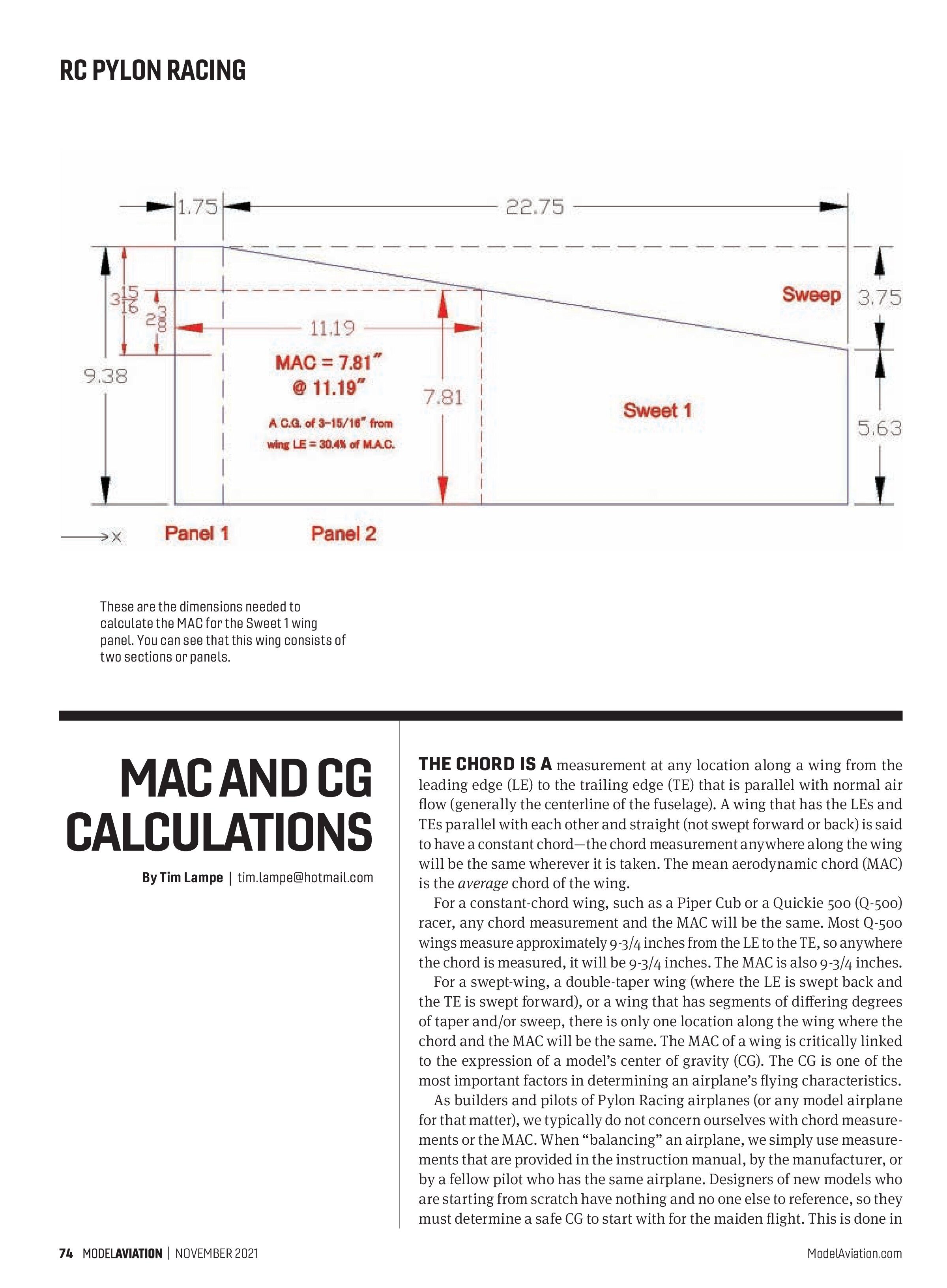
These are the dimensions needed to calculate the MAC for the Sweet 1 wing panel. You can see that this wing consists of two sections or panels.

THE CHORD IS A measurement at any location along a wing from the leading edge (LE) to the trailing edge (TE) that is parallel with normal air flow (generally the centerline of the fuselage). A wing that has the LEs and TEs parallel with each other and straight (not swept forward or back) is said to have a constant chord—the chord measurement anywhere along the wing will be the same wherever it is taken. The mean aerodynamic chord (MAC) is the average chord of the wing.
For a constant-chord wing, such as a Piper Cub or a Quickie 500 (Q-500) racer, any chord measurement and the MAC will be the same. Most Q-500 wings measure approximately 9-3/4 inches from the LE to the TE, so anywhere the chord is measured, it will be 9-3/4 inches. The MAC is also 9-3/4 inches.
For a swept-wing, a double-taper wing (where the LE is swept back and the TE is swept forward), or a wing that has segments of differing degrees of taper and/or sweep, there is only one location along the wing where the chord and the MAC will be the same. The MAC of a wing is critically linked to the expression of a model’s center of gravity (CG). The CG is one of the most important factors in determining an airplane’s flying characteristics.
As builders and pilots of Pylon Racing airplanes (or any model airplane for that matter), we typically do not concern ourselves with chord measurements or the MAC. When “balancing” an airplane, we simply use measurements that are provided in the instruction manual, by the manufacturer, or by a fellow pilot who has the same airplane. Designers of new models who are starting from scratch have nothing and no one else to reference, so they must determine a safe CG to start with for the maiden flight. This is done in relation to, or as a percentage of, the MAC.
Although my newest Pylon racer, a P-51 Mustang-based Miss Foxy Lady, wasn’t new, and approximate CG measurements were provided to me, I still wasn’t quite sure, so partially for fun, I decided to make my own calculations for comparison to what I had been told. I remembered the strict logbook recordkeeping for airplanes that were in development during my time in the research and development department at Hobbico. Back then, we did plenty of MAC and CG calculations because we constantly had new models in development. It was critical that we knew the MAC and a safe starting CG for a maiden flight.
I decided to calculate the MAC and the CG in relation to the MAC for my Sweet 1, an airplane I was already familiar and comfortable with. When I knew those figures, I could do the calculations for the Miss Foxy Lady and compare the two. I know it’s a bit of a leap to assume that the CG for one model will work on a different model with an entirely different wing shape, airfoil, moments, etc., but my main objective was simply to come up with some figures for comparison between the two airplanes and to compare it with the CG location that I had been provided for the Miss Foxy Lady.
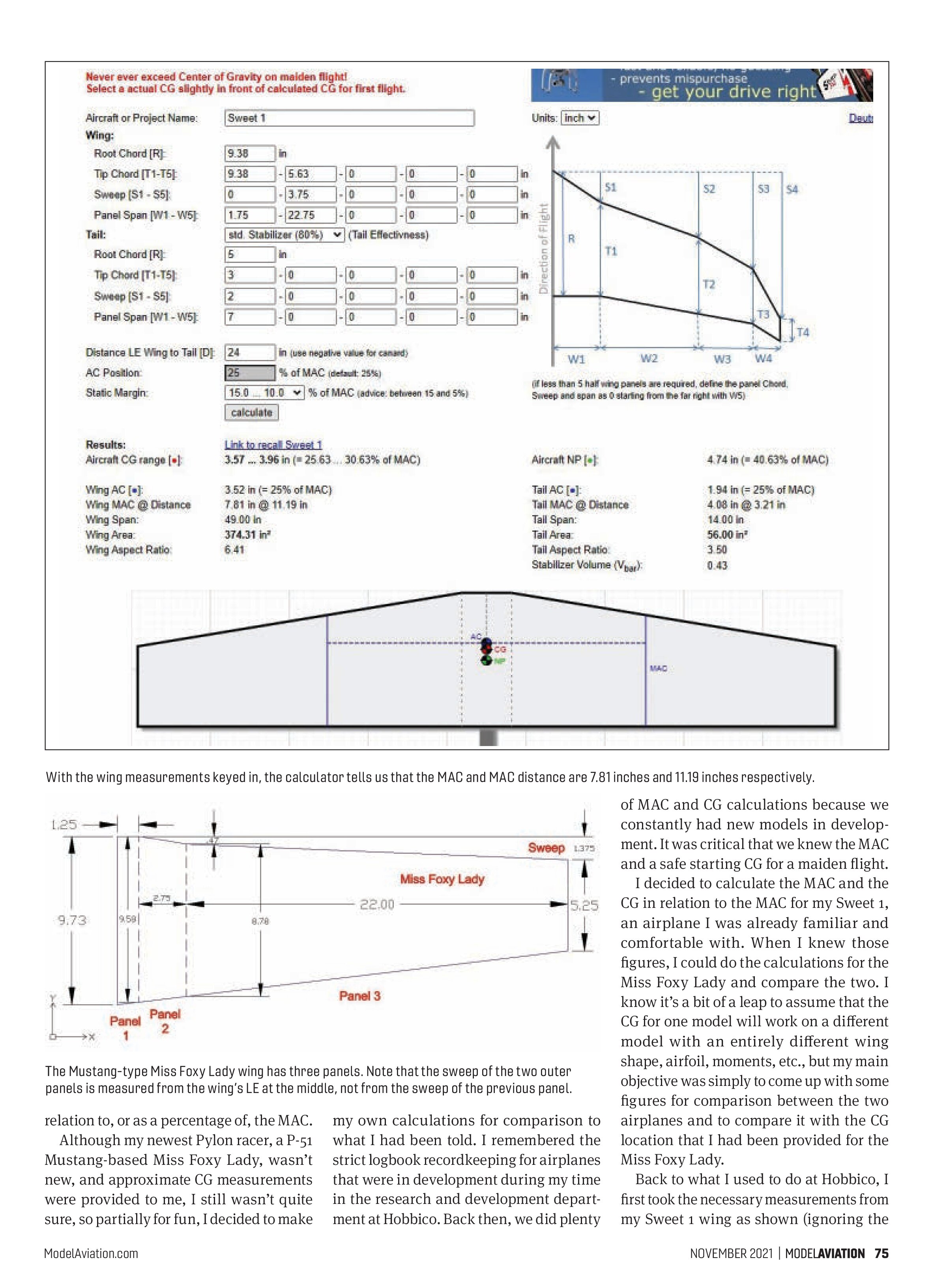
Back to what I used to do at Hobbico, I first took the necessary measurements from my Sweet 1 wing as shown (ignoring the


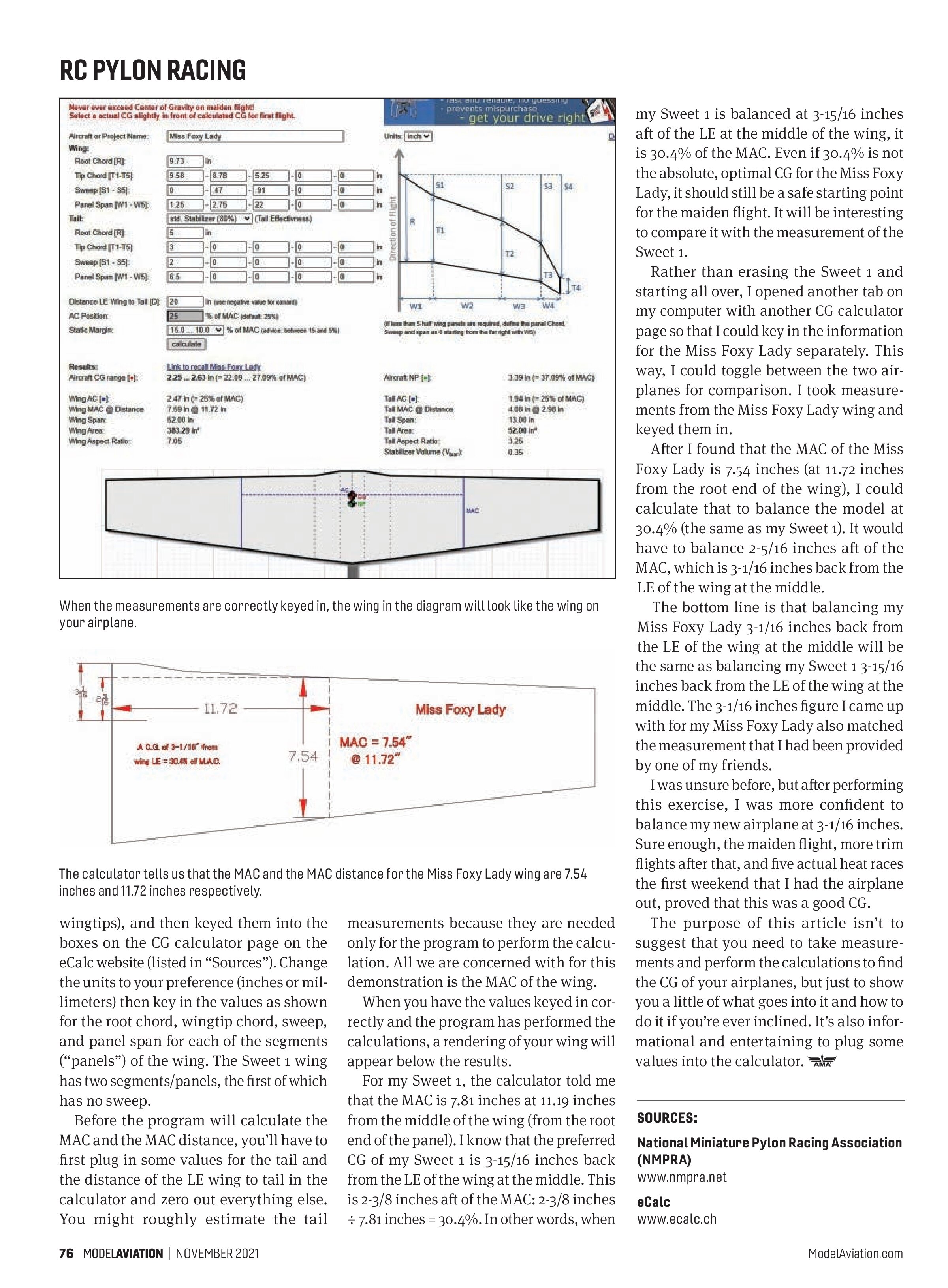
When the measurements are correctly keyed in, the wing in the diagram will look like the wing on your airplane.

The calculator tells us that the MAC and the MAC distance for the Miss Foxy Lady wing are 7.54 inches and 11.72 inches respectively.
wingtips), and then keyed them into the boxes on the CG calculator page on the eCalc website (listed in “Sources”). Change the units to your preference (inches or millimeters) then key in the values as shown for the root chord, wingtip chord, sweep, and panel span for each of the segments (“panels”) of the wing. The Sweet 1 wing has two segments/panels, the first of which has no sweep.
Before the program will calculate the MAC and the MAC distance, you’ll have to first plug in some values for the tail and the distance of the LE wing to tail in the calculator and zero out everything else. You might roughly estimate the tail measurements because they are needed only for the program to perform the calculation. All we are concerned with for this demonstration is the MAC of the wing.
When you have the values keyed in correctly and the program has performed the calculations, a rendering of your wing will appear below the results.
For my Sweet 1, the calculator told me that the MAC is 7.81 inches at 11.19 inches from the middle of the wing (from the root end of the panel). I know that the preferred CG of my Sweet 1 is 3-15/16 inches back from the LE of the wing at the middle. This is 2-3/8 inches aft of the MAC: 2-3/8 inches ÷ 7.81 inches = 30.4%. In other words, when my Sweet 1 is balanced at 3-15/16 inches aft of the LE at the middle of the wing, it is 30.4% of the MAC. Even if 30.4% is not the absolute, optimal CG for the Miss Foxy Lady, it should still be a safe starting point for the maiden flight. It will be interesting to compare it with the measurement of the Sweet 1.
Rather than erasing the Sweet 1 and starting all over, I opened another tab on my computer with another CG calculator page so that I could key in the information for the Miss Foxy Lady separately. This way, I could toggle between the two airplanes for comparison. I took measurements from the Miss Foxy Lady wing and keyed them in.
After I found that the MAC of the Miss Foxy Lady is 7.54 inches (at 11.72 inches from the root end of the wing), I could calculate that to balance the model at 30.4% (the same as my Sweet 1). It would have to balance 2-5/16 inches aft of the MAC, which is 3-1/16 inches back from the LE of the wing at the middle.
The bottom line is that balancing my Miss Foxy Lady 3-1/16 inches back from the LE of the wing at the middle will be the same as balancing my Sweet 1 3-15/16 inches back from the LE of the wing at the middle. The 3-1/16 inches figure I came up with for my Miss Foxy Lady also matched the measurement that I had been provided by one of my friends.
I was unsure before, but after performing this exercise, I was more confident to balance my new airplane at 3-1/16 inches. Sure enough, the maiden flight, more trim flights after that, and five actual heat races the first weekend that I had the airplane out, proved that this was a good CG.
The purpose of this article isn’t to suggest that you need to take measurements and perform the calculations to find the CG of your airplanes, but just to show you a little of what goes into it and how to do it if you’re ever inclined. It’s also informational and entertaining to plug some values into the calculator.
SOURCES:
National Miniature Pylon Racing Association (NMPRA)
www.nmpra.net
eCalc
www.ecalc.ch