How-To Roundup
Modelers’ Tips
and Tricks
In the spirit of Model Aviation’s annual “Build Month,” we asked several contributors and columnists for some of their favorite tips and tricks. Tim Lampe, Joe Vermillion, Sal Calvagna, Stan Alexander, Mark Snowden, and Pat Tritle offer advice for building, finishing, and troubleshooting. We hope you’ll find this information helpful!

DISCOVER MORE ONLINE!
For additional tips and tricks, visit www.modelaircraft.org/ibuildama.
Cutting Holes in Fiberglass
By Tim Lampe | tim.lampe@hotmail.com
Many of today’s model aircraft kits include at least one or two fiberglass parts such as wheel pants or a cowling. Some of the aircraft in my favorite category, RC Pylon Racing, are made entirely of fiberglass and other composite materials.
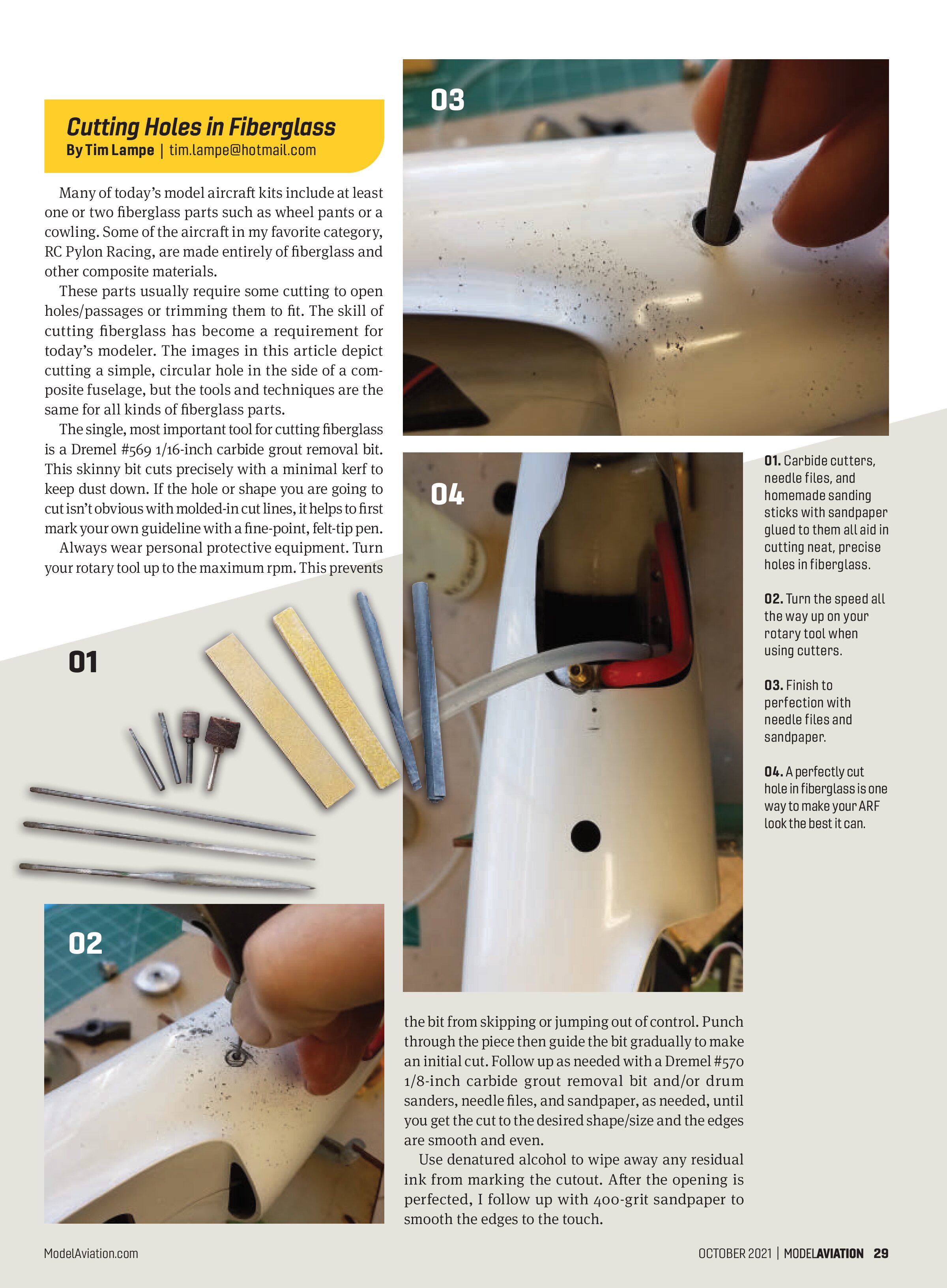
These parts usually require some cutting to open holes/passages or trimming them to fit. The skill of cutting fiberglass has become a requirement for today’s modeler. The images in this article depict cutting a simple, circular hole in the side of a composite fuselage, but the tools and techniques are the same for all kinds of fiberglass parts.


The single, most important tool for cutting fiberglass is a Dremel #569 1/16-inch carbide grout removal bit. This skinny bit cuts precisely with a minimal kerf to keep dust down. If the hole or shape you are going to cut isn’t obvious with molded-in cut lines, it helps to first mark your own guideline with a fine-point, felt-tip pen.
Always wear personal protective equipment. Turn your rotary tool up to the maximum rpm. This prevents

the bit from skipping or jumping out of control. Punch through the piece then guide the bit gradually to make an initial cut. Follow up as needed with a Dremel #570 1/8-inch carbide grout removal bit and/or drum sanders, needle files, and sandpaper, as needed, until you get the cut to the desired shape/size and the edges are smooth and even.
Use denatured alcohol to wipe away any residual ink from marking the cutout. After the opening is perfected, I follow up with 400-grit sandpaper to smooth the edges to the touch.

Hinges and Control Surface Setup
By Joe Vermillion | uawflyer@gmail.com

One of the questions that I often get is how to hinge and set up the control surfaces on a model. This relatively simple process can be confusing when we start talking about things such as the hinge line, deflection, differential, etc. I felt that this would be a good chance to discuss the basics to hopefully help you understand and be more successful as you build.
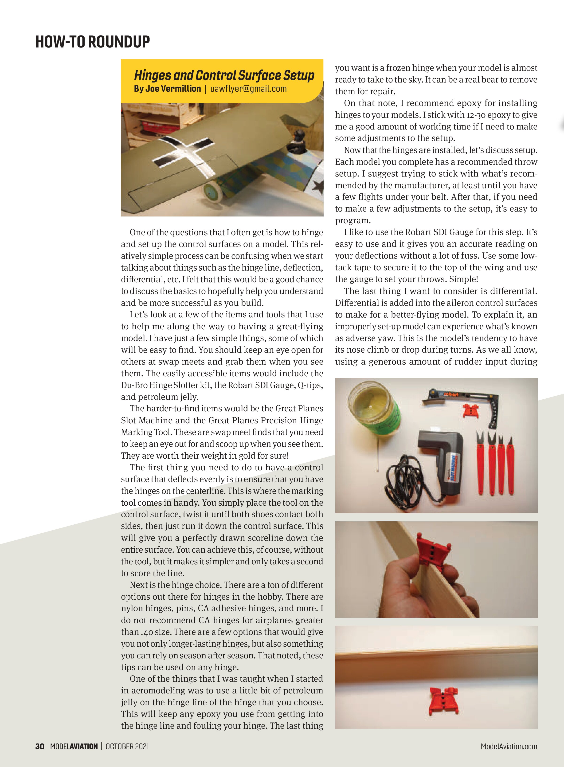
Let’s look at a few of the items and tools that I use to help me along the way to having a great-flying model. I have just a few simple things, some of which will be easy to find. You should keep an eye open for others at swap meets and grab them when you see them. The easily accessible items would include the Du-Bro Hinge Slotter kit, the Robart SDI Gauge, Q-tips, and petroleum jelly.
The harder-to-find items would be the Great Planes Slot Machine and the Great Planes Precision Hinge Marking Tool. These are swap meet finds that you need to keep an eye out for and scoop up when you see them. They are worth their weight in gold for sure!
The first thing you need to do to have a control surface that deflects evenly is to ensure that you have the hinges on the centerline. This is where the marking tool comes in handy. You simply place the tool on the control surface, twist it until both shoes contact both sides, then just run it down the control surface. This will give you a perfectly drawn scoreline down the entire surface. You can achieve this, of course, without the tool, but it makes it simpler and only takes a second to score the line.
Next is the hinge choice. There are a ton of different options out there for hinges in the hobby. There are nylon hinges, pins, CA adhesive hinges, and more. I do not recommend CA hinges for airplanes greater than .40 size. There are a few options that would give you not only longer-lasting hinges, but also something you can rely on season after season. That noted, these tips can be used on any hinge.
One of the things that I was taught when I started in aeromodeling was to use a little bit of petroleum jelly on the hinge line of the hinge that you choose. This will keep any epoxy you use from getting into the hinge line and fouling your hinge. The last thing you want is a frozen hinge when your model is almost ready to take to the sky. It can be a real bear to remove them for repair.


On that note, I recommend epoxy for installing hinges to your models. I stick with 12-30 epoxy to give me a good amount of working time if I need to make some adjustments to the setup.
Now that the hinges are installed, let’s discuss setup. Each model you complete has a recommended throw setup. I suggest trying to stick with what’s recommended by the manufacturer, at least until you have a few flights under your belt. After that, if you need to make a few adjustments to the setup, it’s easy to program.
I like to use the Robart SDI Gauge for this step. It’s easy to use and it gives you an accurate reading on your deflections without a lot of fuss. Use some low-tack tape to secure it to the top of the wing and use the gauge to set your throws. Simple!
The last thing I want to consider is differential. Differential is added into the aileron control surfaces to make for a better-flying model. To explain it, an improperly set-up model can experience what’s known as adverse yaw. This is the model’s tendency to have its nose climb or drop during turns. As we all know, using a generous amount of rudder input during coordinated turns can correct a lot of this, but why not make it a little better with some differential?
To achieve this, all that is needed is a little bit of setup and you’ll notice a big difference. Set up the control surface so that you have less throw on the bottom than you have on the top. It can be as simple as programming differential in your computer radio or, in the case of a single servo set up on the ailerons, you could use a circular control horn to achieve the same results manually. In most cases, only a little is needed to make a huge difference. Most of the recommended settings can be found in the manuals and/or directly from the manufacturers.
I hope this information helps you to set up your models for fun and exciting flights!
Dealing With Heat-Related Issues
By Sal Calvagna | rcgiants@optoline.net
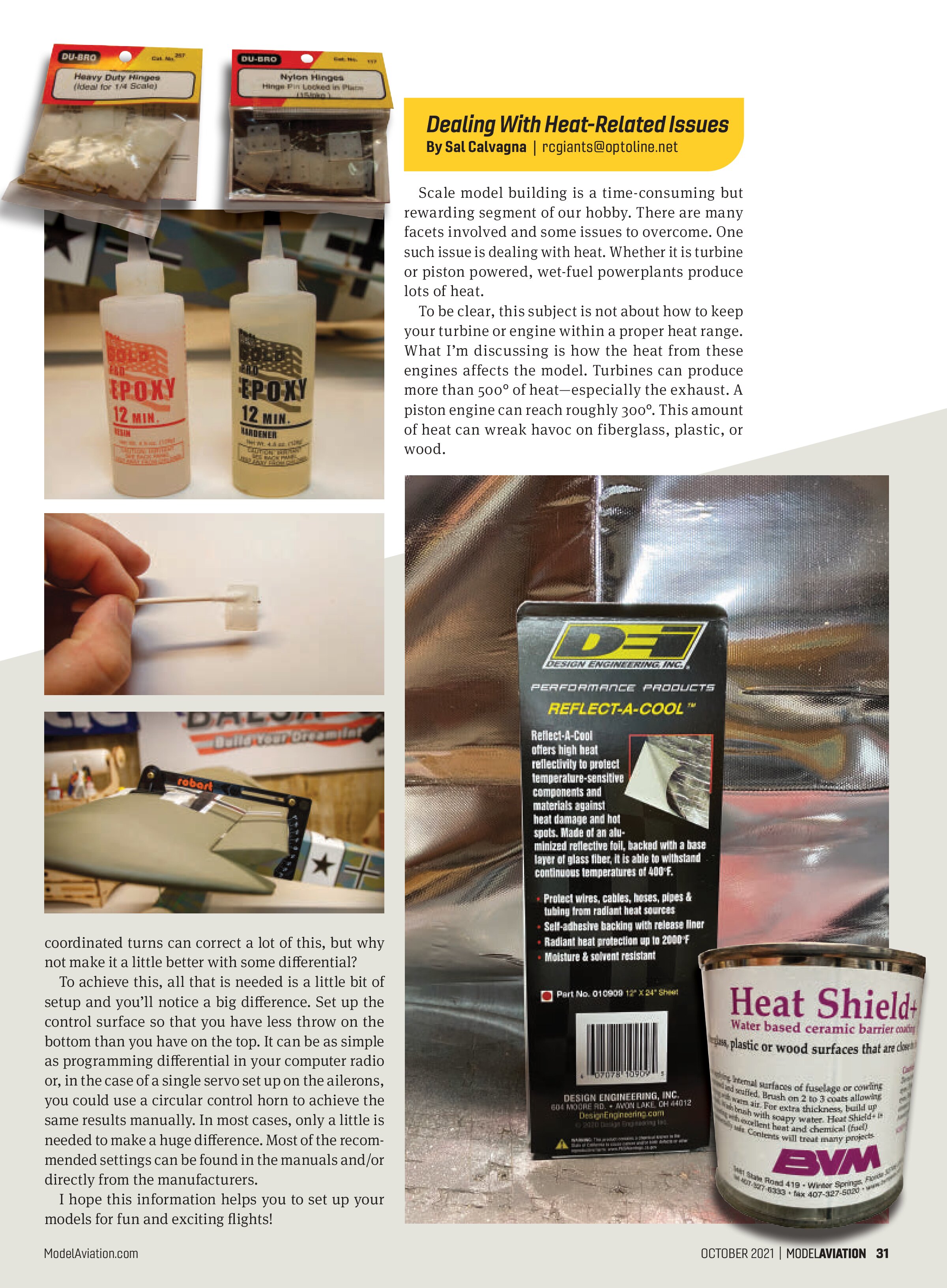
Scale model building is a time-consuming but rewarding segment of our hobby. There are many facets involved and some issues to overcome. One such issue is dealing with heat. Whether it is turbine or piston powered, wet-fuel powerplants produce lots of heat.
To be clear, this subject is not about how to keep your turbine or engine within a proper heat range. What I’m discussing is how the heat from these engines affects the model. Turbines can produce more than 500° of heat—especially the exhaust. A piston engine can reach roughly 300°. This amount of heat can wreak havoc on fiberglass, plastic, or wood.


Hinges and Hinging
By Stan Alexander | onawing4602@att.net
Sometimes, the smallest parts of a model are the most critical in its performance. Most of us have seen a model airplane at the field, and as it makes a pass in front of everyone, you hear a telltale sound called flutter. Sometimes you don’t even hear the flutter before the control surface fails. It could be the ailerons, flaps, or the death pop of the elevator letting go. All are evidence of a control surface that was improperly installed or a hinge gap that was too large.
There are all types of hinges for scale and sport models or any other kind. Now we have so many choices for modeling materials, including foam, that we can ponder the different types of parts to put into the model. There are still several parts that manufacturers who produce hinges, hinge guides, and materials use to make hinges.
Sig Manufacturing Co., with late designer Mike Gretz, made the first CA hinges, which work well on most 20- to 60-size models. Of course, there are many other types that are used including Robart Hinge Points or others that often replicate the full-scale hinges on flaps, ailerons, elevators, or rudders. They are easy to use and can be sealed in place with epoxy using a little petroleum jelly to keep the center hinge joint free.
CA hinges are probably the most common today. Many sport models, as well as others, use CA hinges on every control surface on the model. The method of application is simple, and I always keep a box of tissues handy to wipe off any excess CA glue from the adjoining flight surface. I also allow these to fully dry then perform a pull test on them to make sure that everything has cured and that the hinge will do its job.
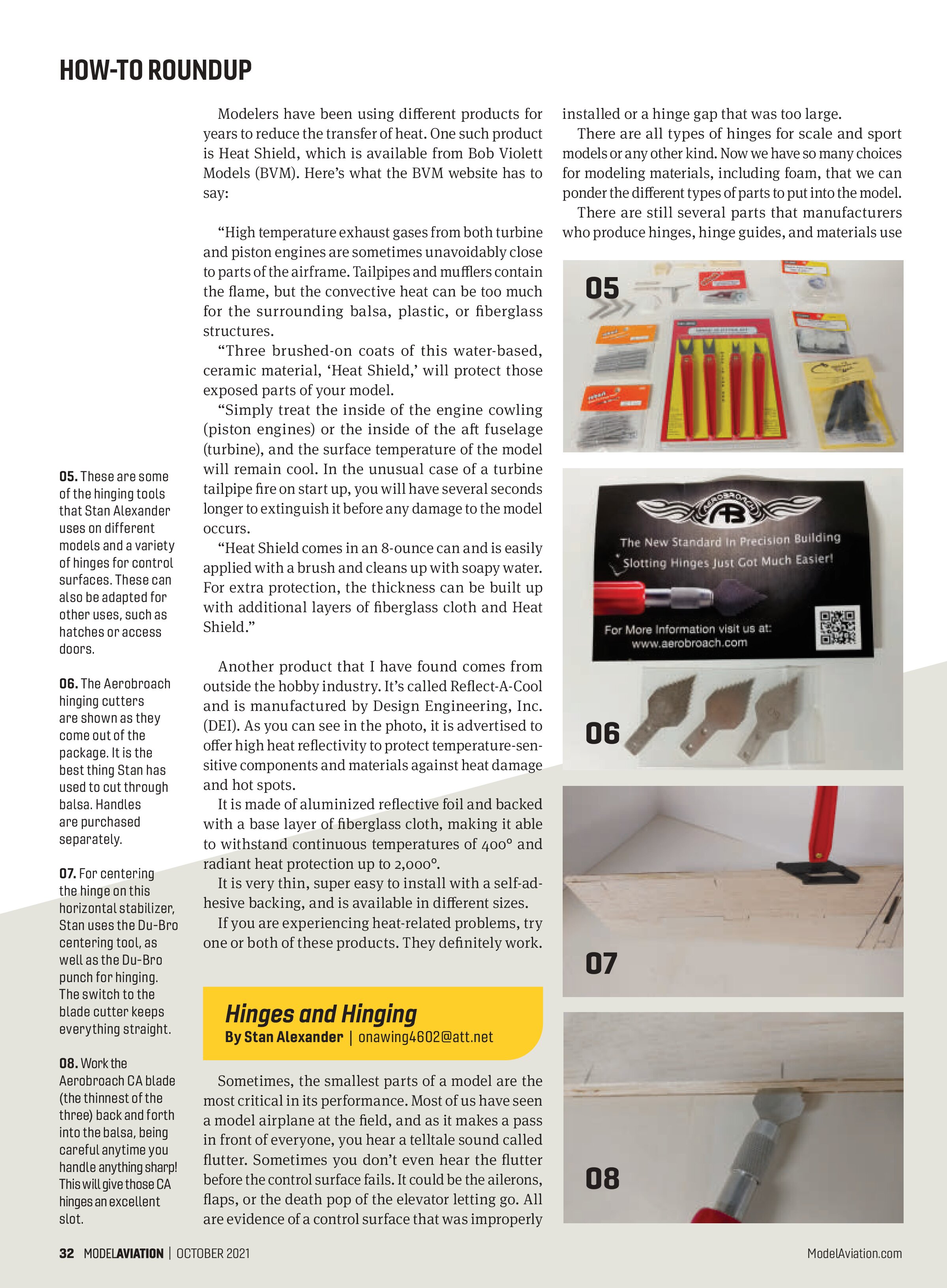
Having the proper hinge-slotting tools is a huge help in making good tight hinges and reducing the hinge gaps on models. These can be purchased from suppliers such as Aerobroach LLC or Du-Bro. I’ve found the ones from Aerobroach LLC to be very accurate and work well.
Start out with the thinnest slotting blade for CA hinges and mark the centerline on the back of the surface into which you plan to cut the slot. Carefully cut the slot into the wood at a flat angle.

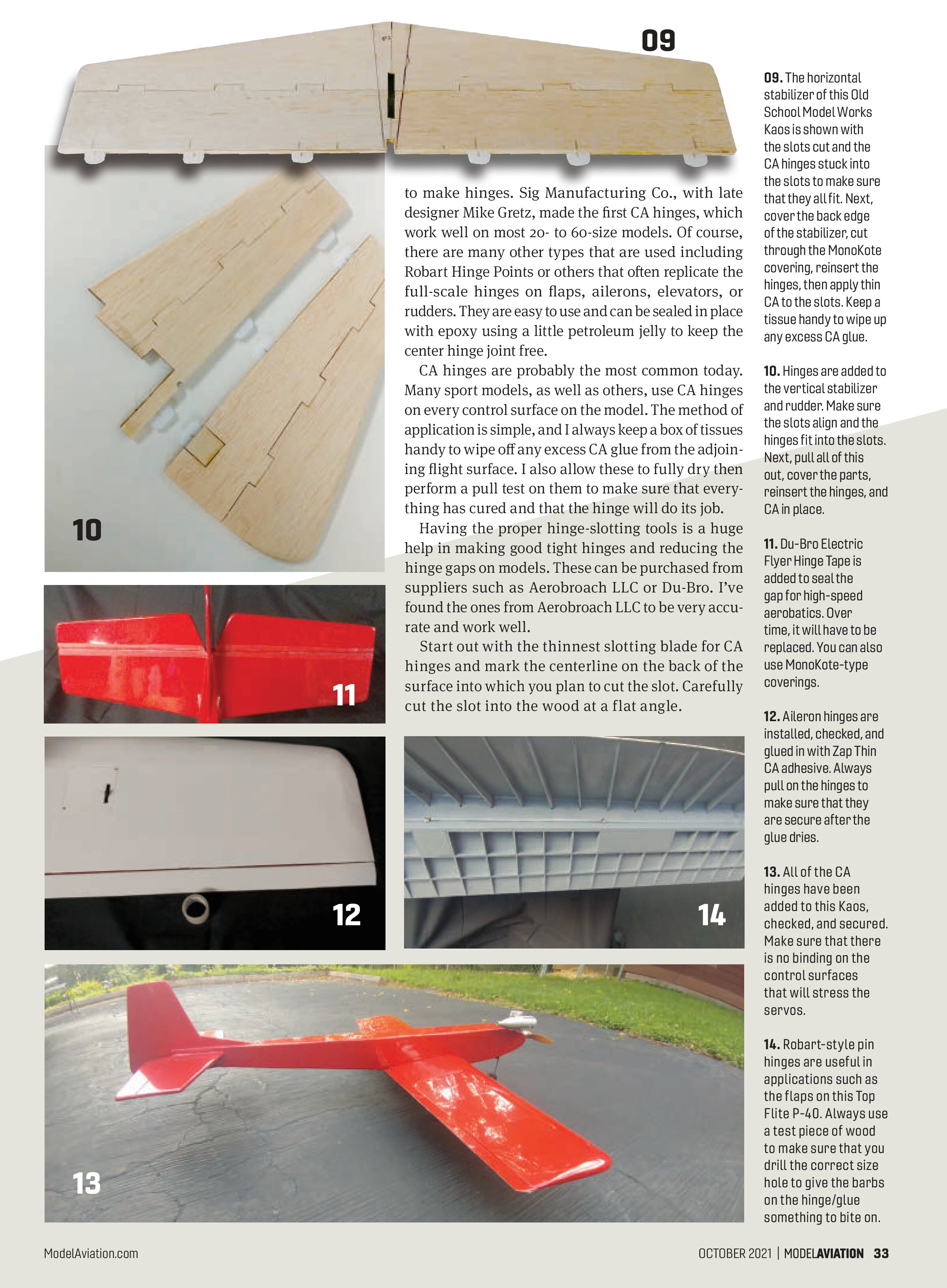
09. The horizontal stabilizer of this Old School Model Works Kaos is shown with the slots cut and the CA hinges stuck into the slots to make sure that they all fit. Next, cover the back edge of the stabilizer, cut through the MonoKote covering, reinsert the hinges, then apply thin CA to the slots. Keep a tissue handy to wipe up any excess CA glue.


10. Hinges are added to the vertical stabilizer and rudder. Make sure the slots align and the hinges fit into the slots. Next, pull all of this out, cover the parts, reinsert the hinges, and CA in place.
11. Du-Bro Electric Flyer Hinge Tape is added to seal the gap for high-speed aerobatics. Over time, it will have to be replaced. You can also use MonoKote-type coverings.
12. Aileron hinges are installed, checked, and glued in with Zap Thin CA adhesive. Always pull on the hinges to make sure after the glue dries.
13. All of the CA hinges have been added to this Kaos, checked, and secured. Make sure that there is no binding on the control surfaces that will stress the servos.
14. Robart-style pin hinges are useful in applications such as the flaps on this Top Flite P-40. Always use a test piece of wood to make sure that you drill the correct size hole to give the barbs on the hinge/glue something to bite on.


Hinge Tape and Sealing Hinge Gaps
There are several types of hinge tape available or materials that you can use to seal those hinge gaps. Sometimes it’s built into an ARF, other times someone—maybe not you, but whoever built the model—didn’t do a great job installing the hinges, but those gaps can be sealed shut. Materials such as MonoKote, UltraCote, fabric, or for many electric models, Du-Bro Hinge Tape can be used.
Be sure to move the control surface to its maximum deflection and hold it there before you start adding the hinge tape. This will allow the hinge to work properly for any movement in flight. Apply the hinge tape for the entire length of the control surface, whether it’s for the ailerons or the elevator.
Take your time and always test-fit the CA hinges and others. Make sure your fit and gap are tight and minimized.
Fair skies and tailwinds.

Items Needed
- Rare-earth magnets (available at Harbor Freight)
- 1/8 x 1/8-inch stringers (Mark Snowden’s were basswood)
- 1/8-inch balsa sheet at least 3 inches wide
- Your front and back formers (F1 and F2) should be made of 1/8-inch basswood or light plywood
- Either Titebond II or medium CA glue.
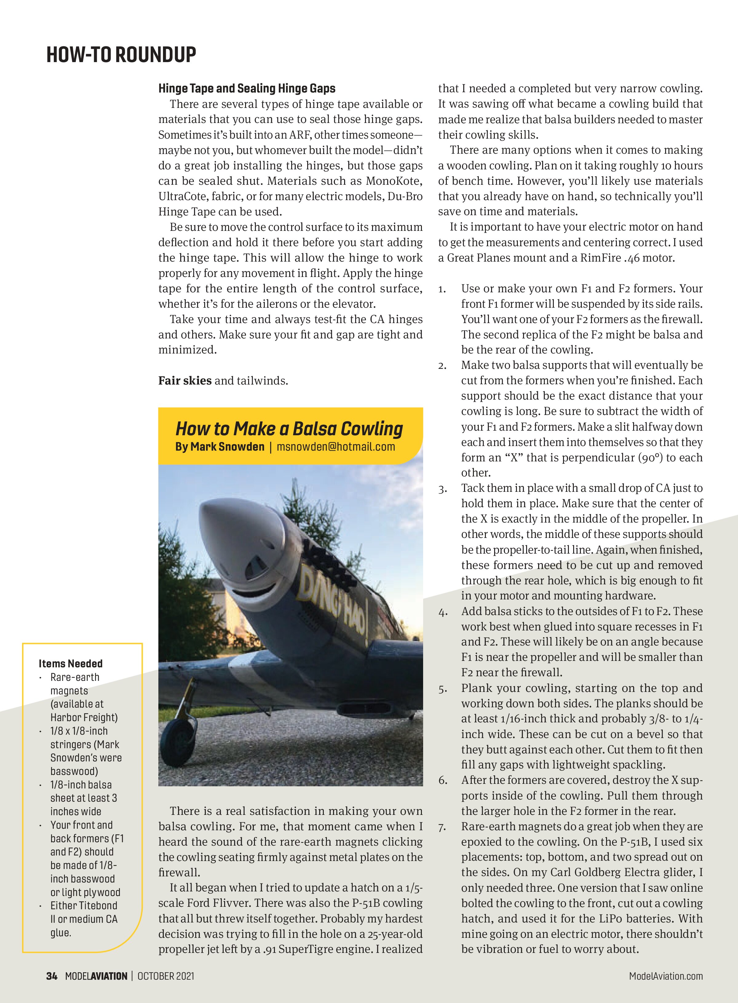
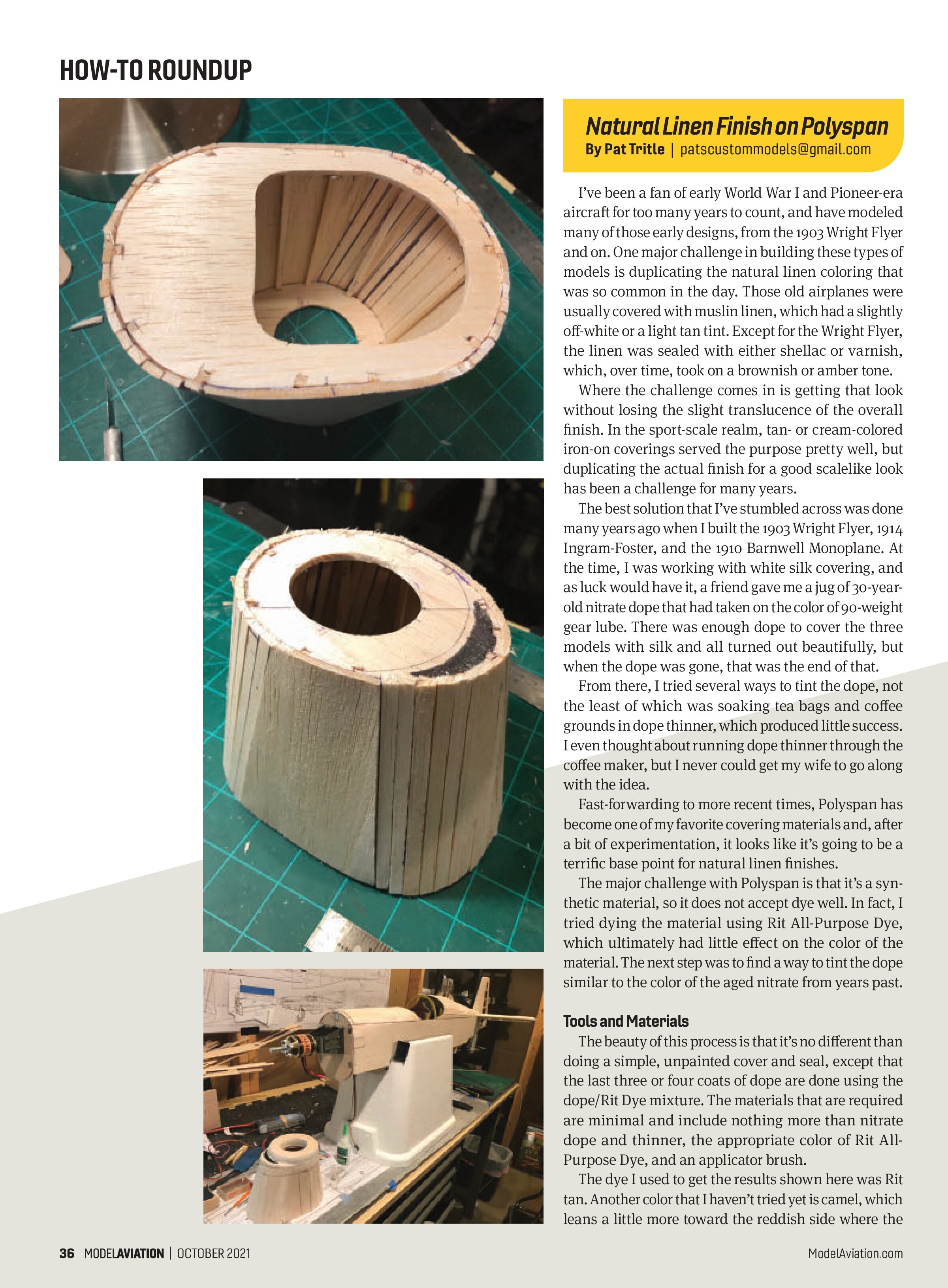
There is a real satisfaction in making your own balsa cowling. For me, that moment came when I heard the sound of the rare-earth magnets clicking the cowling seating firmly against metal plates on the firewall.
It all began when I tried to update a hatch on a 1/5-scale Ford Flivver. There was also the P-51B cowling that all but threw itself together. Probably my hardest decision was trying to fill in the hole on a 25-year-old propeller jet left by a .91 SuperTigre engine. I realized that I needed a completed but very narrow cowling. It was sawing off what became a cowling build that made me realize that balsa builders needed to master their cowling skills.
There are many options when it comes to making a wooden cowling. Plan on it taking roughly 10 hours of bench time. However, you’ll likely use materials that you already have on hand, so technically you’ll save on time and materials.
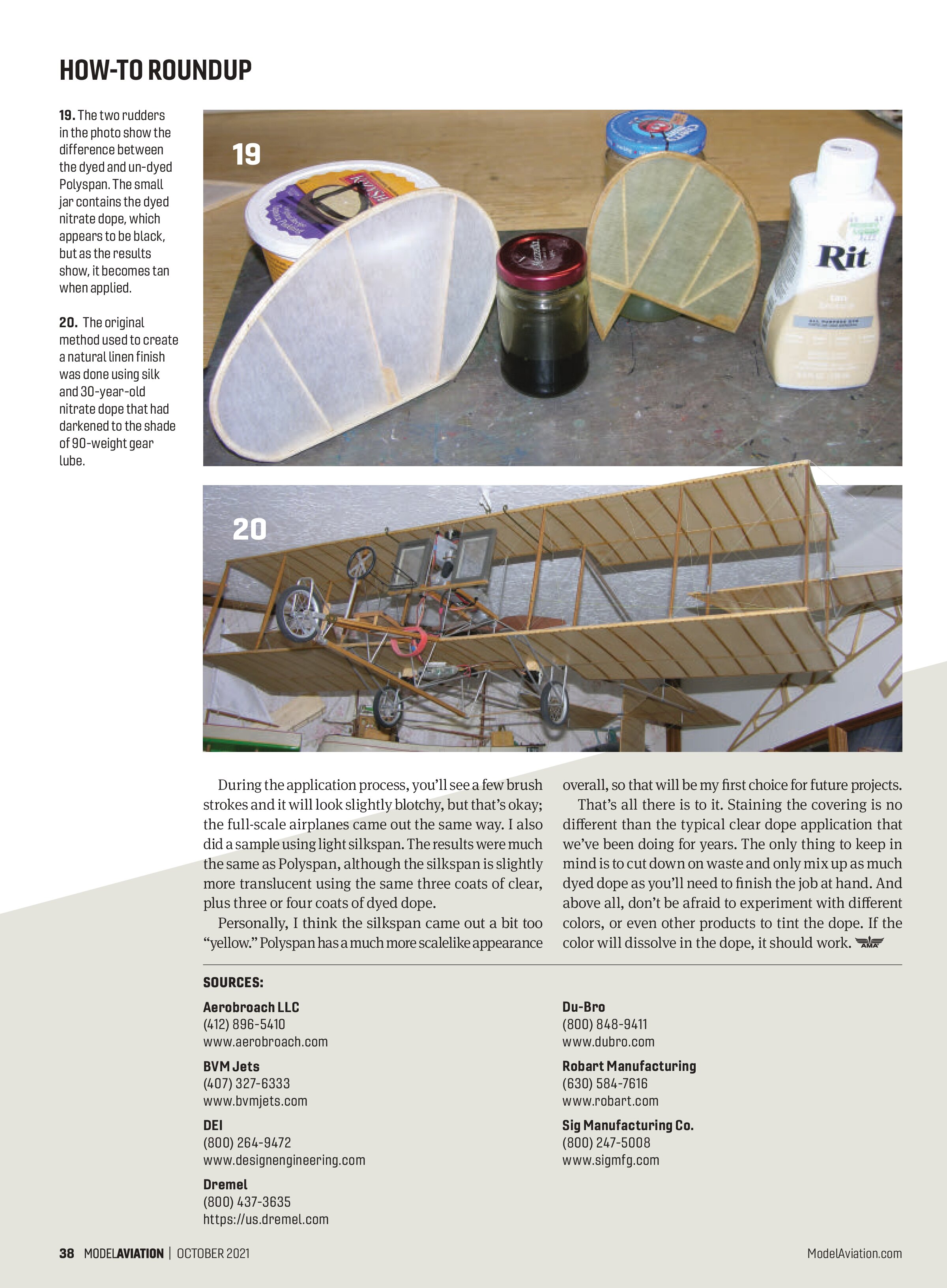
It is important to have your electric motor on hand to get the measurements and centering correct. I used a Great Planes mount and a RimFire .46 motor.
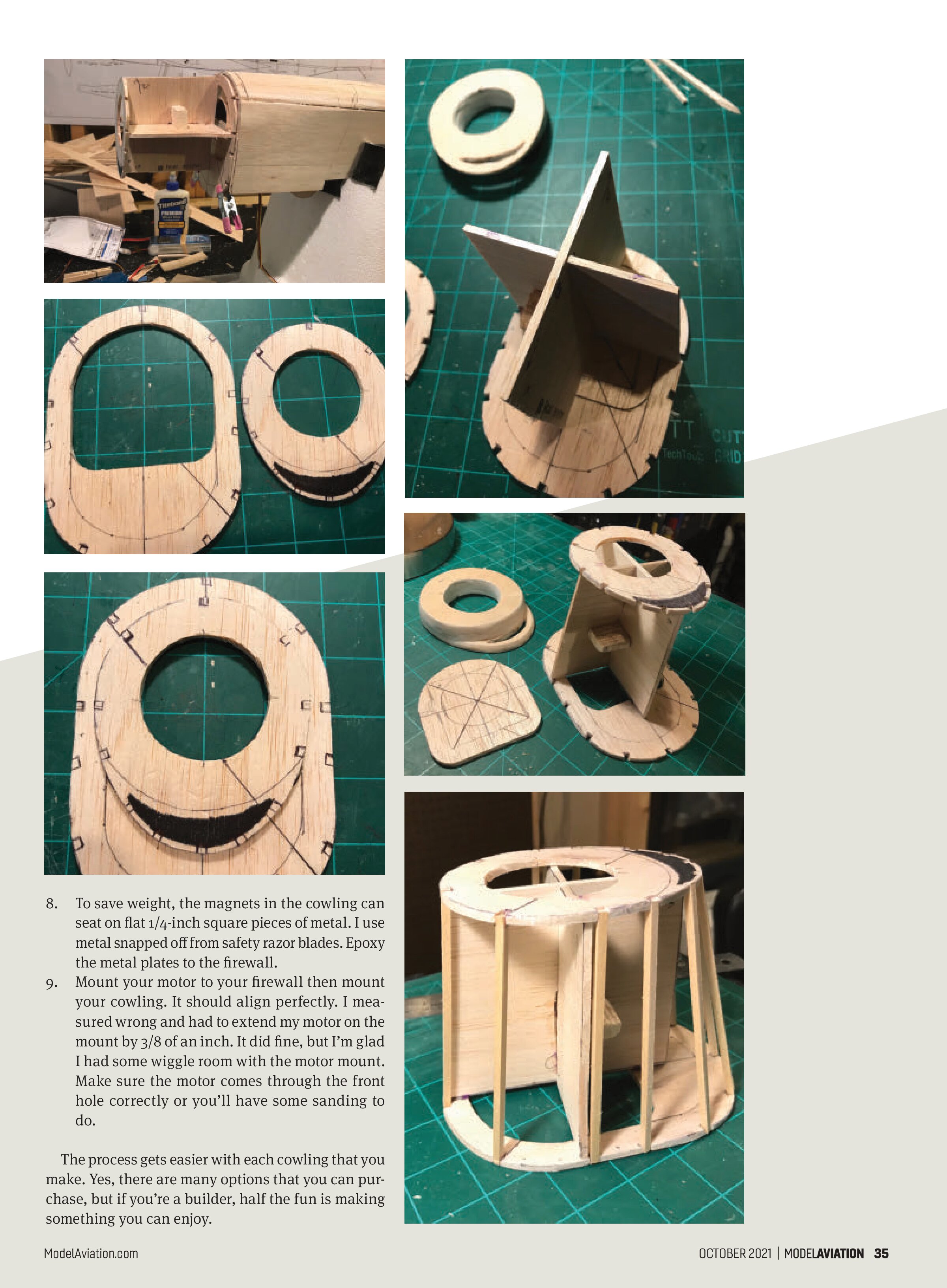
- Use or make your own F1 and F2 formers. Your front F1 former will be suspended by its side rails. You’ll want one of your F2 formers as the firewall. The second replica of the F2 might be balsa and be the rear of the cowling.
- Make two balsa supports that will eventually be cut from the formers when you’re finished. Each support should be the exact distance that your cowling is long. Be sure to subtract the width of your F1 and F2 formers. Make a slit halfway down each and insert them into themselves so that they form an “X” that is perpendicular (90°) to each other.
- Tack them in place with a small drop of CA just to hold them in place. Make sure that the center of the X is exactly in the middle of the propeller. In other words, the middle of these supports should be the propeller-to-tail line. Again, when finished, these formers need to be cut up and removed through the rear hole, which is big enough to fit in your motor and mounting hardware.
- Add balsa sticks to the outsides of F1 to F2. These work best when glued into square recesses in F1 and F2. These will likely be on an angle because F1 is near the propeller and will be smaller than F2 near the firewall.
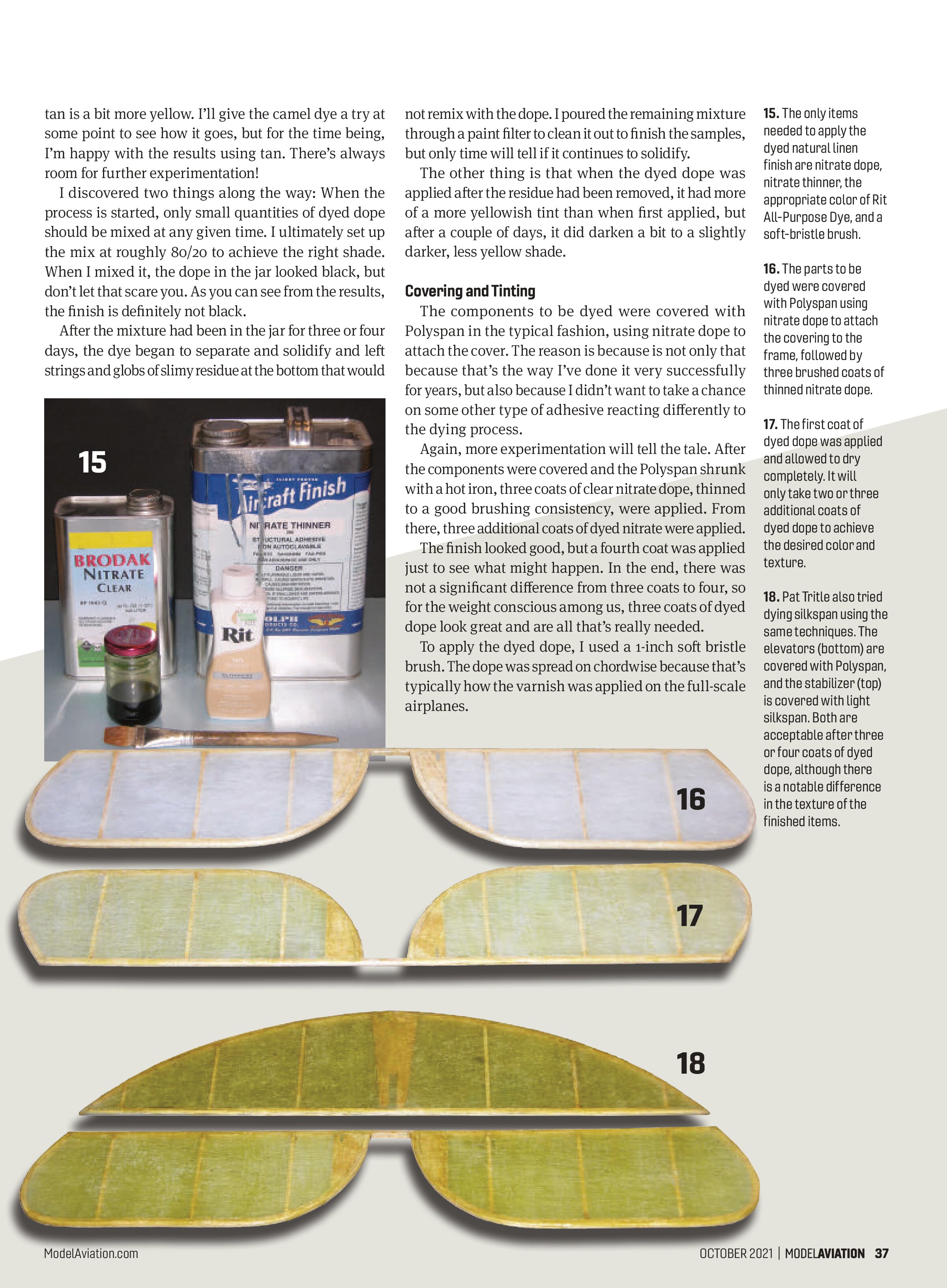
- Plank your cowling, starting on the top and working down both sides. The planks should be at least 1/16-inch thick and probably 3/8- to 1/4-inch wide. These can be cut on a bevel so that they butt against each other. Cut them to fit then fill any gaps with lightweight spackling.
- After the formers are covered, destroy the X supports inside of the cowling. Pull them through the larger hole in the F2 former in the rear.
- Rare-earth magnets do a great job when they are epoxied to the cowling. On the P-51B, I used six placements: top, bottom, and two spread out on the sides. On my Carl Goldberg Electra glider, I only needed three. One version that I saw online bolted the cowling to the front, cut out a cowling hatch, and used it for the LiPo batteries. With mine going on an electric motor, there shouldn’t be vibration or fuel to worry about.


- To save weight, the magnets in the cowling can seat on flat 1/4-inch square pieces of metal. I use metal snapped off from safety razor blades. Epoxy the metal plates to the firewall.
- Mount your motor to your firewall then mount your cowling. It should align perfectly. I measured wrong and had to extend my motor on the mount by 3/8 of an inch. It did fine, but I’m glad I had some wiggle room with the motor mount. Make sure the motor comes through the front hole correctly or you’ll have some sanding to do.
The process gets easier with each cowling that you make. Yes, there are many options that you can purchase, but if you’re a builder, half the fun is making something you can enjoy.
tan is a bit more yellow. I’ll give the camel dye a try at some point to see how it goes, but for the time being, I’m happy with the results using tan. There’s always room for further experimentation!
I discovered two things along the way: When the process is started, only small quantities of dyed dope should be mixed at any given time. I ultimately set up the mix at roughly 80/20 to achieve the right shade. When I mixed it, the dope in the jar looked black, but don’t let that scare you. As you can see from the results, the finish is definitely not black.
After the mixture had been in the jar for three or four days, the dye began to separate and solidify and left strings and globs of slimy residue at the bottom that would

The other thing is that when the dyed dope was applied after the residue had been removed, it had more of a more yellowish tint than when first applied, but after a couple of days, it did darken a bit to a slightly darker, less yellow shade.
Covering and Tinting
The components to be dyed were covered with Polyspan in the typical fashion, using nitrate dope to attach the cover. The reason is because is not only that because that’s the way I’ve done it very successfully for years, but also because I didn’t want to take a chance on some other type of adhesive reacting differently to the dying process.
Again, more experimentation will tell the tale. After the components were covered and the Polyspan shrunk with a hot iron, three coats of clear nitrate dope, thinned to a good brushing consistency, were applied. From there, three additional coats of dyed nitrate were applied. The finish looked good, but a fourth coat was applied just to see what might happen. In the end, there was not a significant difference from three coats to four, so for the weight conscious among us, three coats of dyed dope look great and are all that’s really needed.
To apply the dyed dope, I used a 1-inch soft bristle brush. The dope was spread on chordwise because that’s typically how the varnish was applied on the full-scale airplanes.


During the application process, you’ll see a few brush strokes and it will look slightly blotchy, but that’s okay; the full-scale airplanes came out the same way. I also did a sample using light silkspan. The results were much the same as Polyspan, although the silkspan is slightly more translucent using the same three coats of clear, plus three or four coats of dyed dope.
Personally, I think the silkspan came out a bit too “yellow.” Polyspan has a much more scalelike appearance overall, so that will be my first choice for future projects.
That’s all there is to it. Staining the covering is no different than the typical clear dope application that we’ve been doing for years. The only thing to keep in mind is to cut down on waste and only mix up as much dyed dope as you’ll need to finish the job at hand. And above all, don’t be afraid to experiment with different colors, or even other products to tint the dope. If the color will dissolve in the dope, it should work.
SOURCES:
Aerobroách LLC
(412) 896-5410
www.aerobroach.com
BVM Jets
(407) 327-6333
www.bvmjets.com
DEI
(800) 264-9472
www.designengineering.com
Dremel
(800) 437-3635
https://us.dremel.com
Du-Bro
(800) 848-9411
www.dubro.com
Robart Manufacturing
(630) 584-7616
www.robart.com
Sig Manufacturing Co.
(800) 247-5008
www.sig mfg.com