Fighter Face-Off Park Flyer Edition
Scratch-building and flying opposing aircraft, Part 2
By Paul Kohlmann and Derek Micko
Photos by the authors and as noted

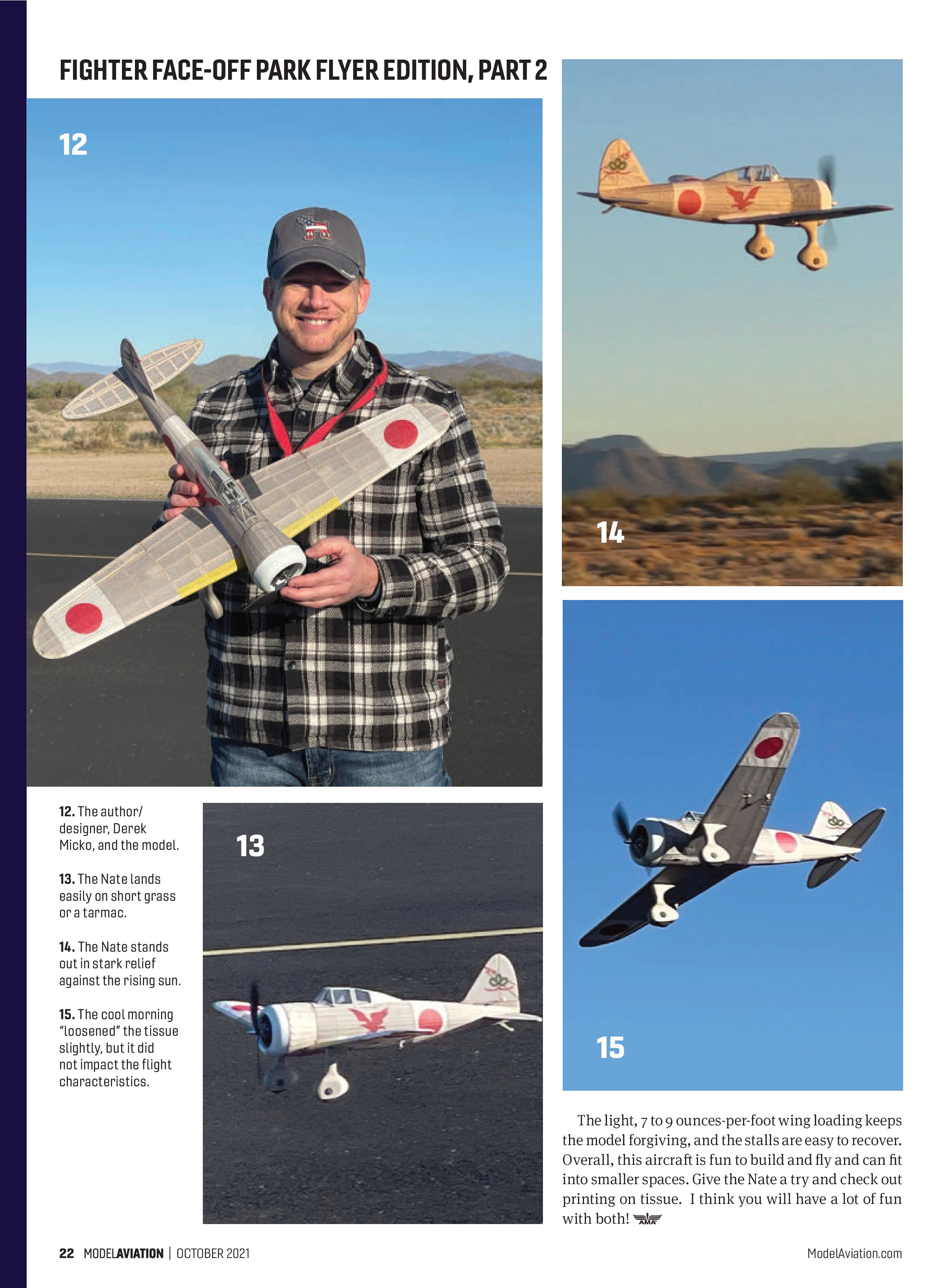
Ki-27 Nate: In last month’s article, I covered the history of the full-scale Nate and the primary construction process. In this article, I will address covering, finishing, and flying the model.
The next major step was to cover the model. Usually, I would turn to a lightweight film, but recently, I have been trying printed tissue and I really like the results. Printed tissue has been popular with Free Flight modelers, and a great reference can be found on Paul Bradley’s website (see “Techniques and References” in the “Sources” list).
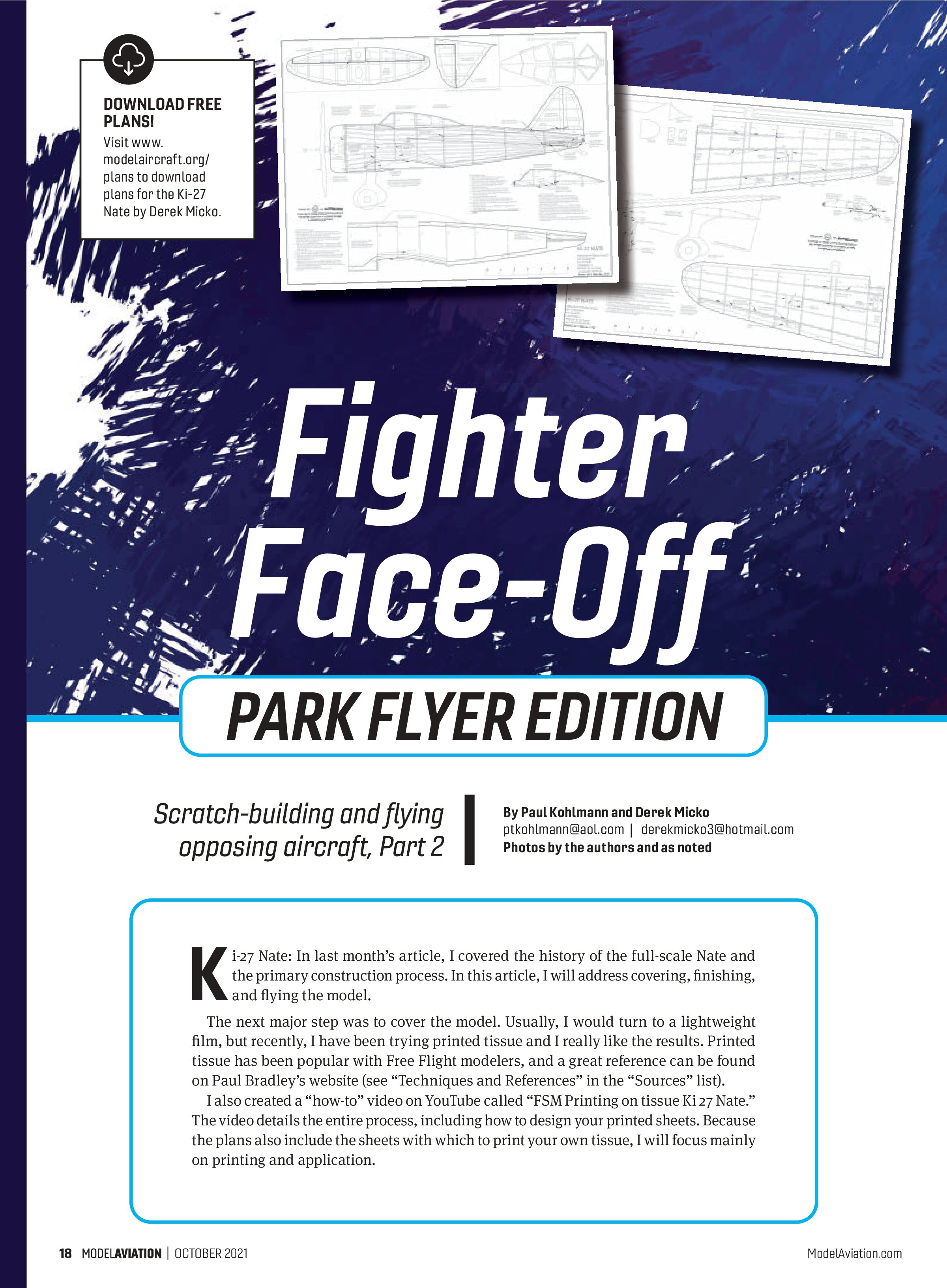
I also created a “how-to” video on YouTube called “FSM Printing on tissue Ki 27 Nate.” The video details the entire process, including how to design your printed sheets. Because the plans also include the sheets with which to print your own tissue, I will focus mainly on printing and application.
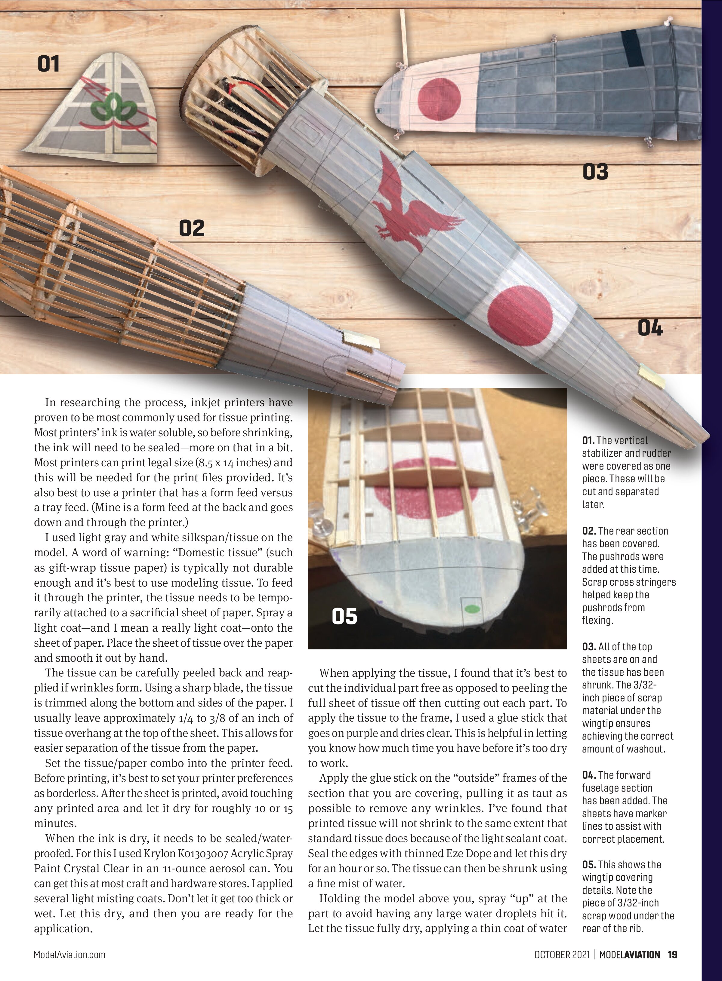
In researching the process, inkjet printers have proven to be most commonly used for tissue printing. Most printers’ ink is water soluble, so before shrinking, the ink will need to be sealed—more on that in a bit. Most printers can print legal size (8.5 x 14 inches) and this will be needed for the print files provided. It’s also best to use a printer that has a form feed versus a tray feed. (Mine is a form feed at the back and goes down and through the printer.)
I used light gray and white silkspan/tissue on the model. A word of warning: “Domestic tissue” (such as gift-wrap tissue paper) is typically not durable enough and it’s best to use modeling tissue. To feed it through the printer, the tissue needs to be temporarily attached to a sacrificial sheet of paper. Spray a light coat—and I mean a really light coat—onto the sheet of paper. Place the sheet of tissue over the paper and smooth it out by hand.
The tissue can be carefully peeled back and reapplied if wrinkles form. Using a sharp blade, the tissue is trimmed along the bottom and sides of the paper. I usually leave approximately 1/4 to 3/8 of an inch of tissue overhang at the top of the sheet. This allows for easier separation of the tissue from the paper.
Set the tissue/paper combo into the printer feed. Before printing, it’s best to set your printer preferences as borderless. After the sheet is printed, avoid touching any printed area and let it dry for roughly 10 or 15 minutes.
When the ink is dry, it needs to be sealed/water-proofed. For this I used Krylon K01303007 Acrylic Spray Paint Crystal Clear in an 11-ounce aerosol can. You can get this at most craft and hardware stores. I applied several light misting coats. Don’t let it get too thick or wet. Let this dry, and then you are ready for the application.
When applying the tissue, I found that it’s best to cut the individual part free as opposed to peeling the full sheet of tissue off then cutting out each part. To apply the tissue to the frame, I used a glue stick that goes on purple and dries clear. This is helpful in letting you know how much time you have before it’s too dry to work.
Apply the glue stick on the “outside” frames of the section that you are covering, pulling it as taut as possible to remove any wrinkles. I’ve found that printed tissue will not shrink to the same extent that standard tissue does because of the light sealant coat. Seal the edges with thinned Eze Dope and let this dry for an hour or so. The tissue can then be shrunk using a fine mist of water.
Holding the model above you, spray “up” at the part to avoid having any large water droplets hit it. Let the tissue fully dry, applying a thin coat of water
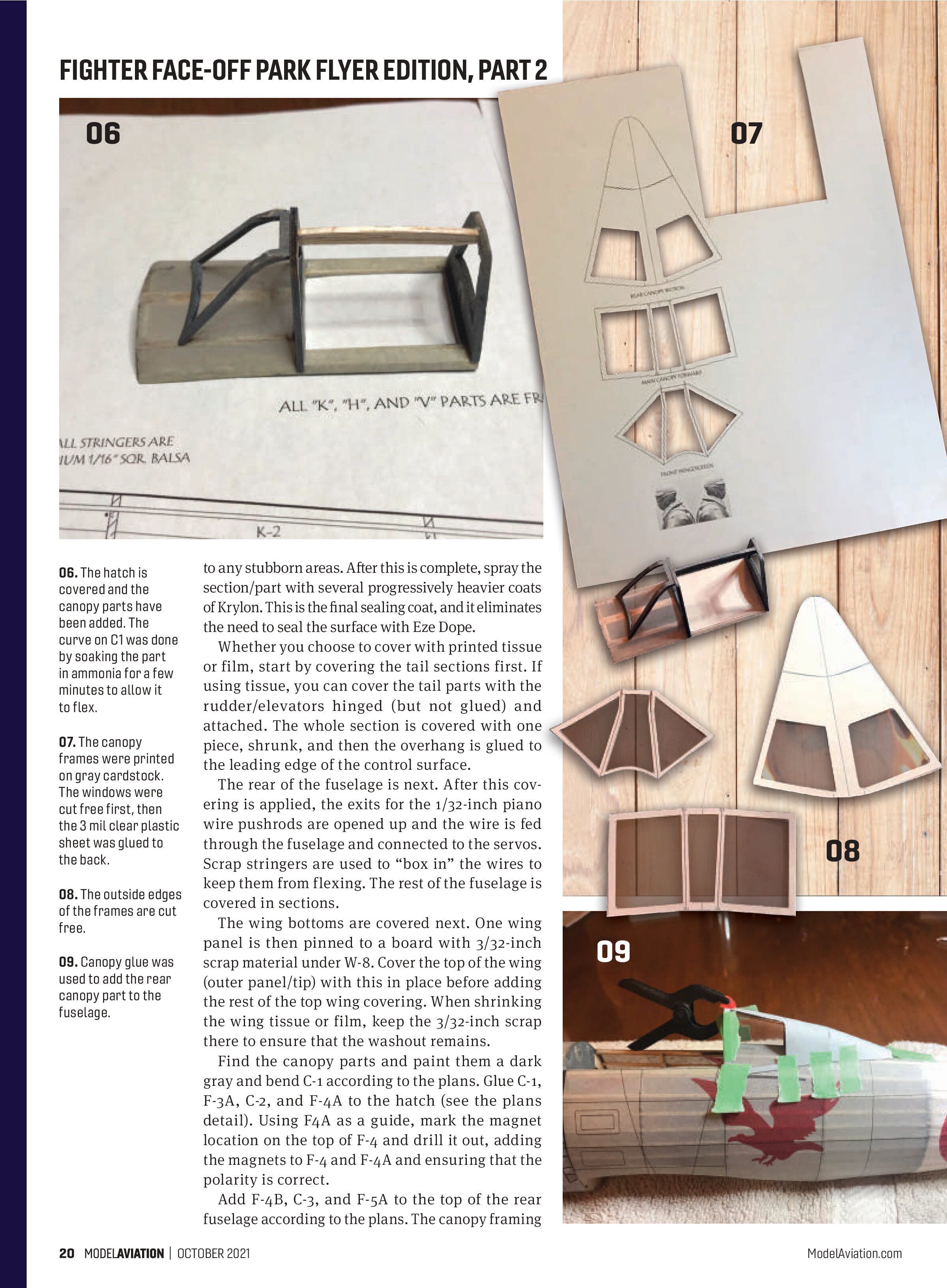
is made from lightweight cardstock and templates are provided. Cut out the interior sections first then the outside edges. Glue these frames on top of thin, clear plastic sheeting. The prototype used 3 mil plastic. Bend and shape it to fit the formers before using canopy glue to attach it. Use canopy glue to also attach the cowling to the CR parts.
Glue the tail sections and wheel pants/spats in place. Check the model’s suggested center of gravity on the plans and position the battery pack fore and aft as needed to get the correct location. The bottom hatch rail inside edge needed a little trimming to allow the pack to be positioned far forward on the prototype.
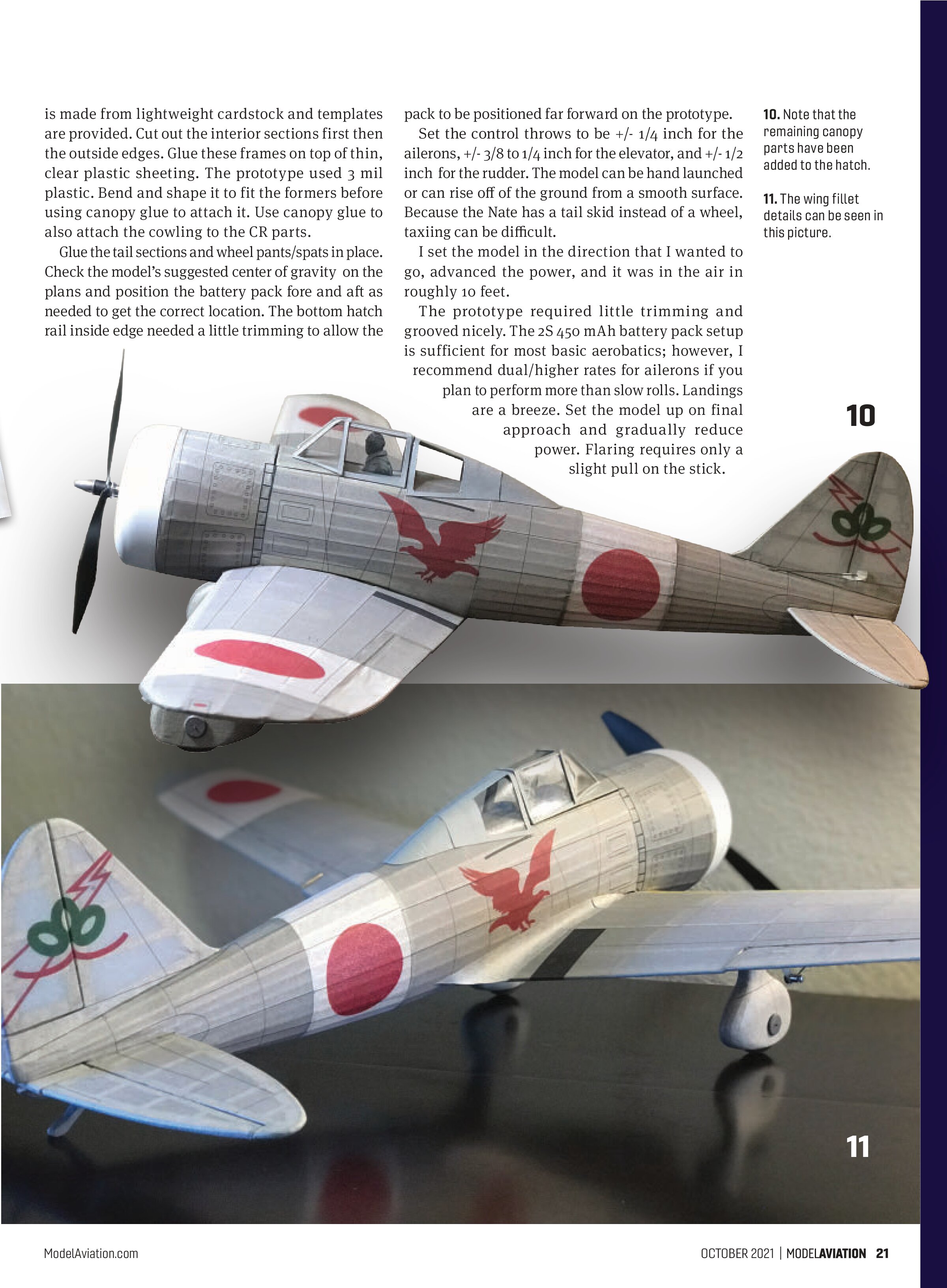
Set the control throws to be +/- 1/4 inch for the ailerons, +/- 3/8 to 1/4 inch for the elevator, and +/- 1/2 inch for the rudder. The model can be hand launched or can rise off of the ground from a smooth surface. Because the Nate has a tail skid instead of a wheel, taxiing can be difficult.
I set the model in the direction that I wanted to go, advanced the power, and it was in the air in roughly 10 feet.
The prototype required little trimming and grooved nicely. The 2S 450 mAh battery pack setup is sufficient for most basic aerobatics; however, I recommend dual/higher rates for ailerons if you plan to perform more than slow rolls. Landings are a breeze. Set the model up on final approach and gradually reduce power. Flaring requires only a slight pull on the stick.


The light, 7 to 9 ounces-per-foot wing loading keeps the model forgiving, and the stalls are easy to recover. Overall, this aircraft is fun to build and fly and can fit into smaller spaces. Give the Nate a try and check out printing on tissue. I think you will have a lot of fun with both!
used 1/8-inch strips of CA hinge material on all of the control surfaces for my prototype.
Fuselage
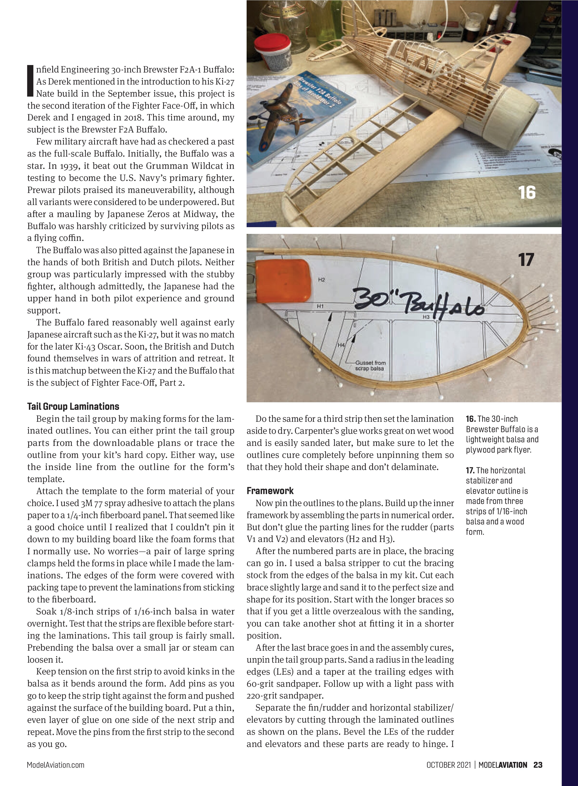
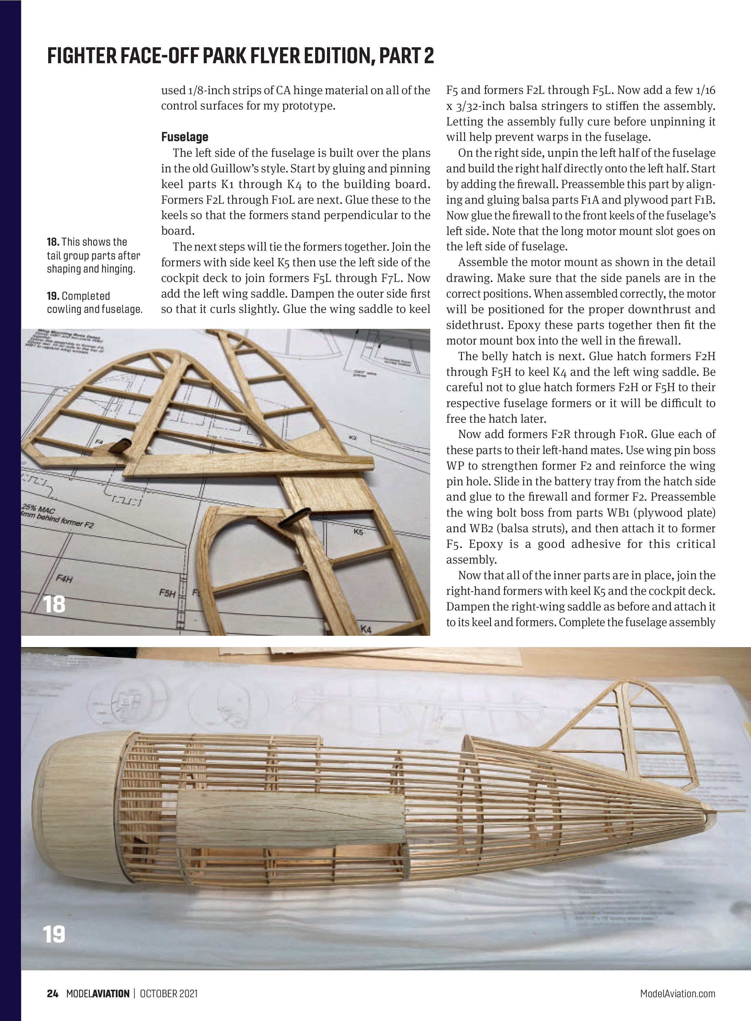
The left side of the fuselage is built over the plans in the old Guillow’s style. Start by gluing and pinning keel parts K1 through K4 to the building board. Formers F2L through F10L are next. Glue these to the keels so that the formers stand perpendicular to the board.
The next steps will tie the formers together. Join the formers with side keel K5 then use the left side of the cockpit deck to join formers F5L through F7L. Now add the left wing saddle. Dampen the outer side first so that it curls slightly. Glue the wing saddle to keel

F5 and formers F2L through F5L. Now add a few 1/16 x 3/32-inch balsa stringers to stiffen the assembly. Letting the assembly fully cure before unpinning it will help prevent warps in the fuselage.
On the right side, unpin the left half of the fuselage and build the right half directly onto the left half. Start by adding the firewall. Preassemble this part by aligning and gluing balsa parts F1A and plywood part F1B. Now glue the firewall to the front keels of the fuselage’s left side. Note that the long motor mount slot goes on the left side of fuselage.
Assemble the motor mount as shown in the detail drawing. Make sure that the side panels are in the correct positions. When assembled correctly, the motor will be positioned for the proper downthrust and sidethrust. Epoxy these parts together then fit the motor mount box into the well in the firewall.
The belly hatch is next. Glue hatch formers F2H through F5H to keel K4 and the left wing saddle. Be careful not to glue hatch formers F2H or F5H to their respective fuselage formers or it will be difficult to free the hatch later.
Now add formers F2R through F10R. Glue each of these parts to their left-hand mates. Use wing pin boss WP to strengthen former F2 and reinforce the wing pin hole. Slide in the battery tray from the hatch side and glue to the firewall and former F2. Preassemble the wing bolt boss from parts WB1 (plywood plate) and WB2 (balsa struts), and then attach it to former F5. Epoxy is a good adhesive for this critical assembly.
Now that all of the inner parts are in place, join the right-hand formers with keel K5 and the cockpit deck. Dampen the right-wing saddle as before and attach it to its keel and formers. Complete the fuselage assembly

by adding the rest of the stringers. Alternate from side to side and check for twisting as you go.
Cowling
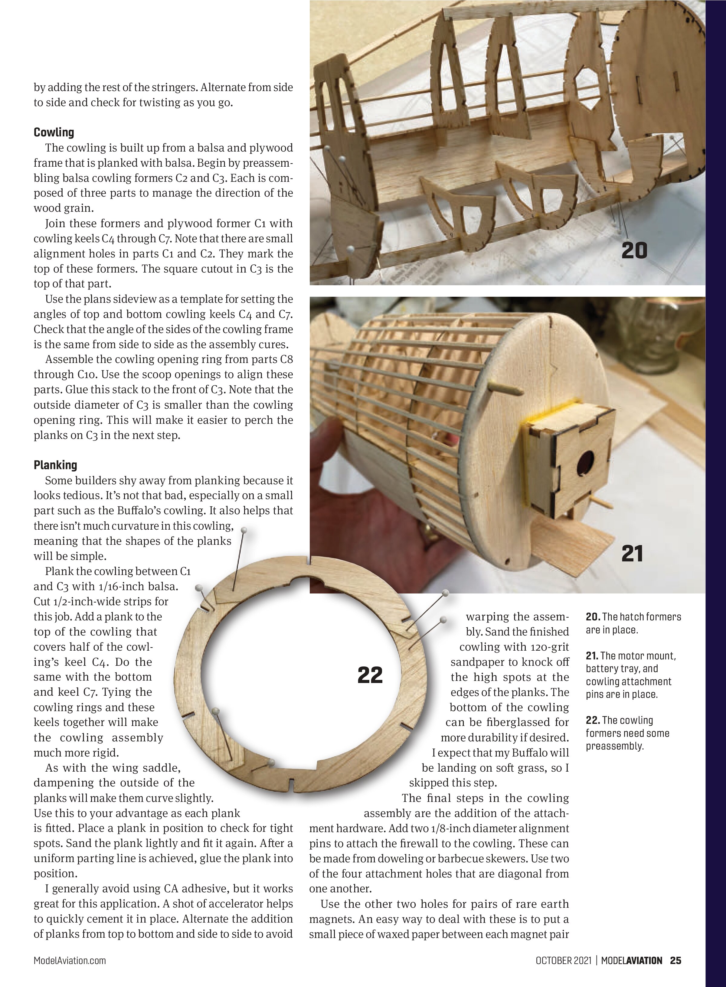
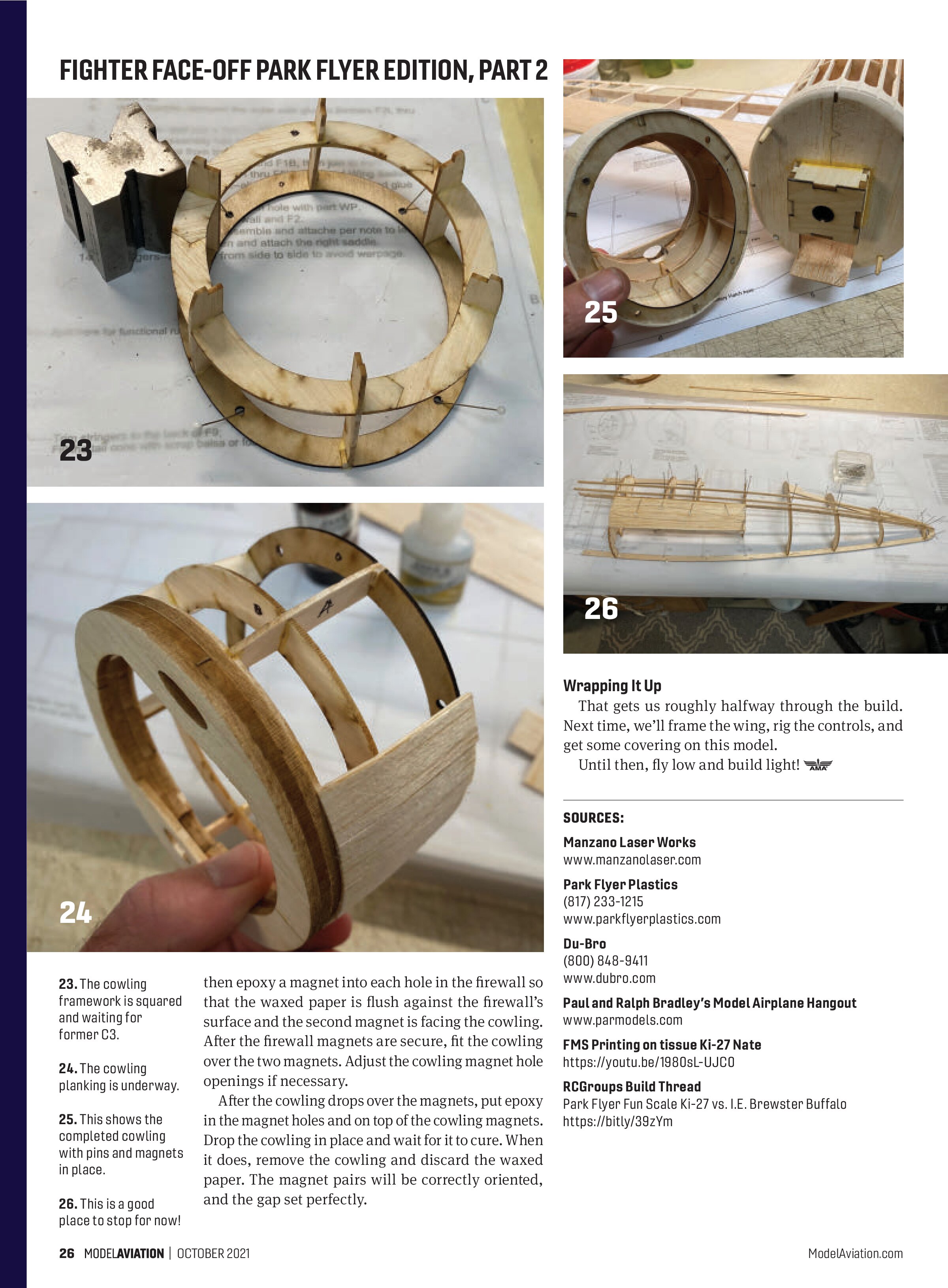
The cowling is built up from a balsa and plywood frame that is planked with balsa. Begin by preassembling balsa cowling formers C2 and C3. Each is composed of three parts to manage the direction of the wood grain.
Join these formers and plywood former C1 with cowling keels C4 through C7. Note that there are small alignment holes in parts C1 and C2. They mark the top of these formers. The square cutout in C3 is the top of that part.
Use the plans sideview as a template for setting the angles of top and bottom cowling keels C4 and C7. Check that the angle of the sides of the cowling frame is the same from side to side as the assembly cures.
Assemble the cowling opening ring from parts C8 through C10. Use the scoop openings to align these parts. Glue this stack to the front of C3. Note that the outside diameter of C3 is smaller than the cowling opening ring. This will make it easier to perch the planks on C3 in the next step.


Planking
Some builders shy away from planking because it looks tedious. It’s not that bad, especially on a small part such as the Buffalo’s cowling. It also helps that there isn’t much curvature in this cowling, meaning that the shapes of the planks will be simple.
Plank the cowling between C1 and C3 with 1/16-inch balsa. Cut 1/2-inch-wide strips for this job. Add a plank to the top of the cowling that covers half of the cowling’s keel C4. Do the same with the bottom and keel C7. Tying the cowling rings and these keels together will make the cowling assembly much more rigid.

As with the wing saddle, dampening the outside of the planks will make them curve slightly. Use this to your advantage as each plank is fitted. Place a plank in position to check for tight spots. Sand the plank lightly and fit it again. After a uniform parting line is achieved, glue the plank into position.
I generally avoid using CA adhesive, but it works great for this application. A shot of accelerator helps to quickly cement it in place. Alternate the addition of planks from top to bottom and side to side to avoid warping the assembly. Sand the finished cowling with 120-grit sandpaper to knock off the high spots at the edges of the planks. The bottom of the cowling can be fiberglassed for more durability if desired.
I expect that my Buffalo will be landing on soft grass, so I skipped this step. The final steps in the cowling assembly are the addition of the attachment hardware. Add two 1/8-inch diameter alignment pins to attach the firewall to the cowling. These can be made from doweling or barbecue skewers. Use two of the four attachment holes that are diagonal from one another.
Use the other two holes for pairs of rare earth magnets. An easy way to deal with these is to put a small piece of waxed paper between each magnet pair


then epoxy a magnet into each hole in the firewall so that the waxed paper is flush against the firewall’s surface and the second magnet is facing the cowling. After the firewall magnets are secure, fit the cowling over the two magnets. Adjust the cowling magnet hole openings if necessary.
After the cowling drops over the magnets, put epoxy in the magnet holes and on top of the cowling magnets. Drop the cowling in place and wait for it to cure. When it does, remove the cowling and discard the waxed paper. The magnet pairs will be correctly oriented, and the gap set perfectly.
Wrapping It Up
That gets us roughly halfway through the build. Next time, we’ll frame the wing, rig the controls, and get some covering on this model. Until then, fly low and build light!
SOURCES:
Manzano Laser Works
www.manzanolaser.com
Park Flyer Plastics
(817) 233-1215
www.parkflyerplastics.com
Du-Bro
(800) 848-9411
www.dubro.com
Paul and Ralph Bradley’s Model Airplane Hangout
www.parmodels.com
EMS Printing on tissue Ki-27 Nate
https://youtu.be/1980sL-UJCO
RCGroups Build Thread
Park Flyer Fun Scale Ki-27 vs. I.E. Brewster Buffalo
https://bit.ly/39zYm