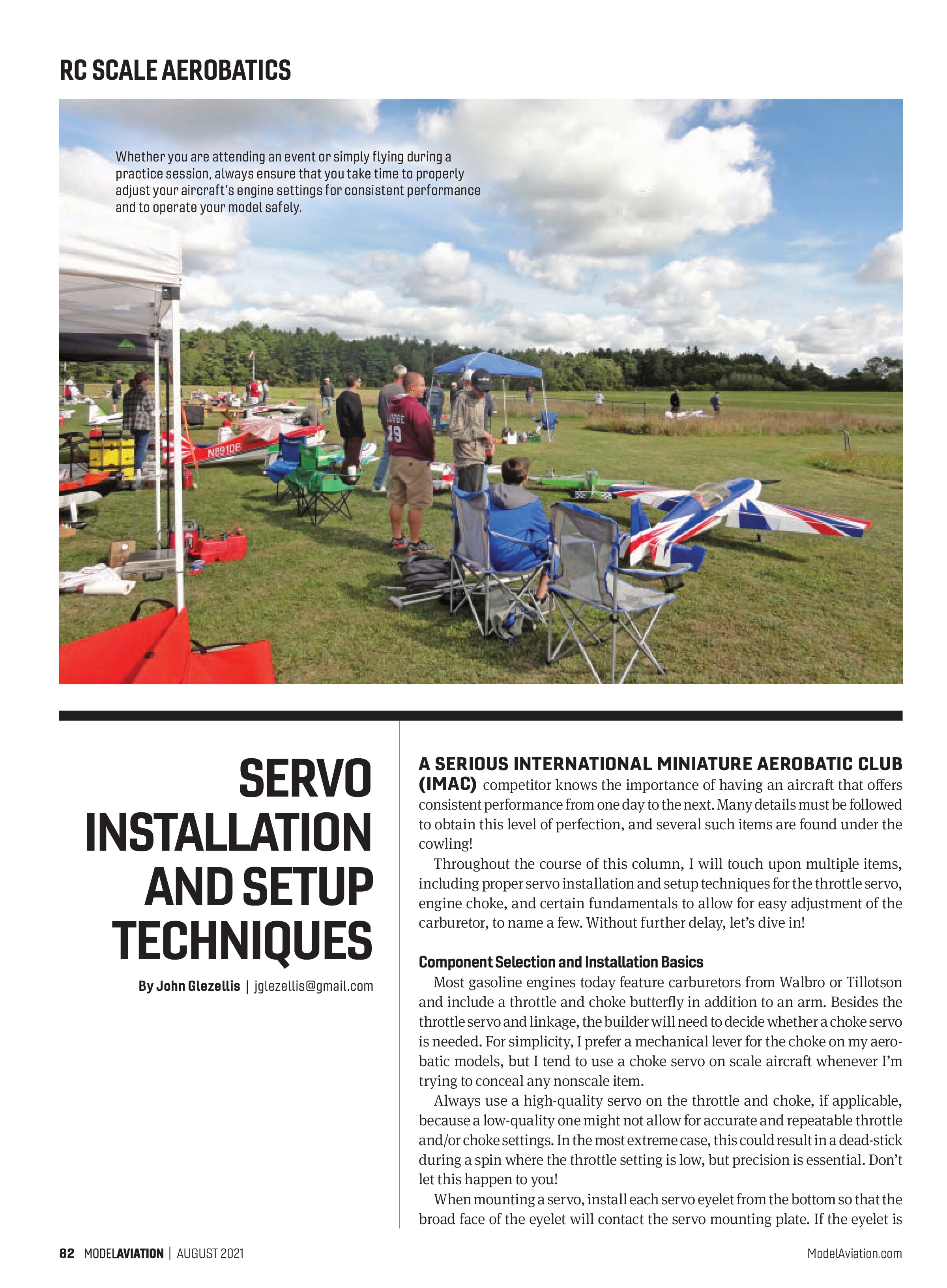
RC SCALE AEROBATICS

SERVO INSTALLATION AND SETUP TECHNIQUES
By John Glezellis | jglezellis@gmail.com
A SERIOUS INTERNATIONAL MINIATURE AEROBATIC CLUB (IMAC) competitor knows the importance of having an aircraft that offers consistent performance from one day to the next. Many details must be followed to obtain this level of perfection, and several such items are found under the cowling!
Throughout the course of this column, I will touch upon multiple items, including proper servo installation and setup techniques for the throttle servo, engine choke, and certain fundamentals to allow for easy adjustment of the carburetor, to name a few. Without further delay, let’s dive in!
Component Selection and Installation Basics
Most gasoline engines today feature carburetors from Walbro or Tillotson and include a throttle and choke butterfly in addition to an arm. Besides the throttle servo and linkage, the builder will need to decide whether a choke servo is needed. For simplicity, I prefer a mechanical lever for the choke on my aerobatic models, but I tend to use a choke servo on scale aircraft whenever I’m trying to conceal any nonscale item.
Always use a high-quality servo on the throttle and choke, if applicable, because a low-quality one might not allow for accurate and repeatable throttle and/or choke settings. In the most extreme case, this could result in a dead-stick during a spin where the throttle setting is low, but precision is essential. Don’t let this happen to you!
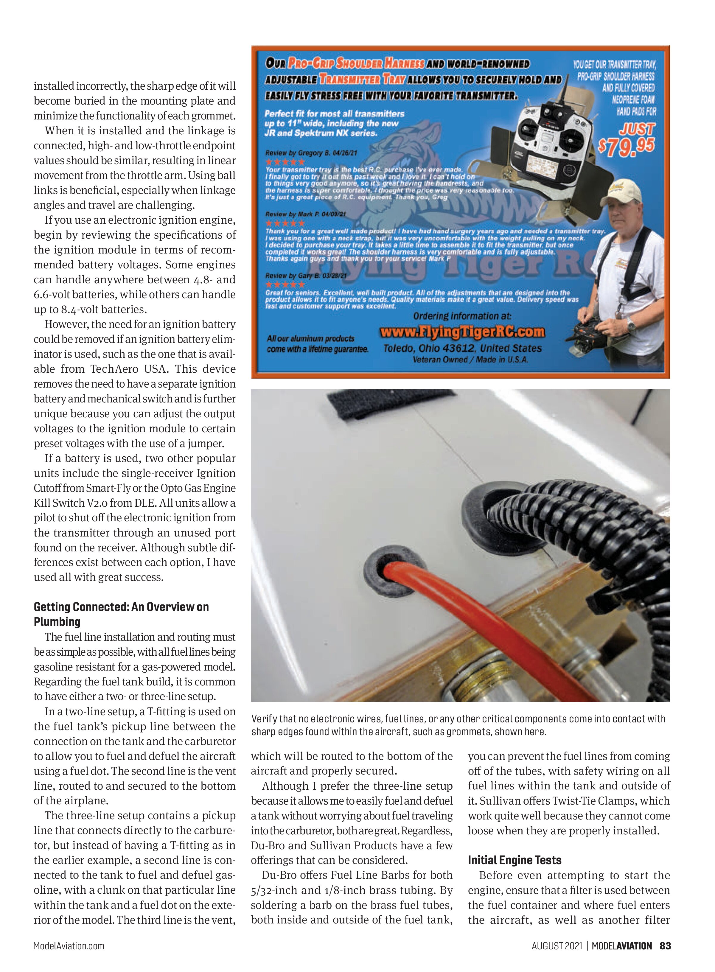
When mounting a servo, install each servo eyelet from the bottom so that the broad face of the eyelet will contact the servo mounting plate. If the eyelet is installed incorrectly, the sharp edge of it will become buried in the mounting plate and minimize the functionality of each grommet.
When it is installed and the linkage is connected, high- and low-throttle endpoint values should be similar, resulting in linear movement from the throttle arm. Using ball links is beneficial, especially when linkage angles and travel are challenging.
If you use an electronic ignition engine, begin by reviewing the specifications of the ignition module in terms of recommended battery voltages. Some engines can handle anywhere between 4.8- and 6.6-volt batteries, while others can handle up to 8.4-volt batteries.
However, the need for an ignition battery could be removed if an ignition battery eliminator is used, such as the one that is available from TechAero USA. This device removes the need to have a separate ignition battery and mechanical switch and is further unique because you can adjust the output voltages to the ignition module to certain preset voltages with the use of a jumper.
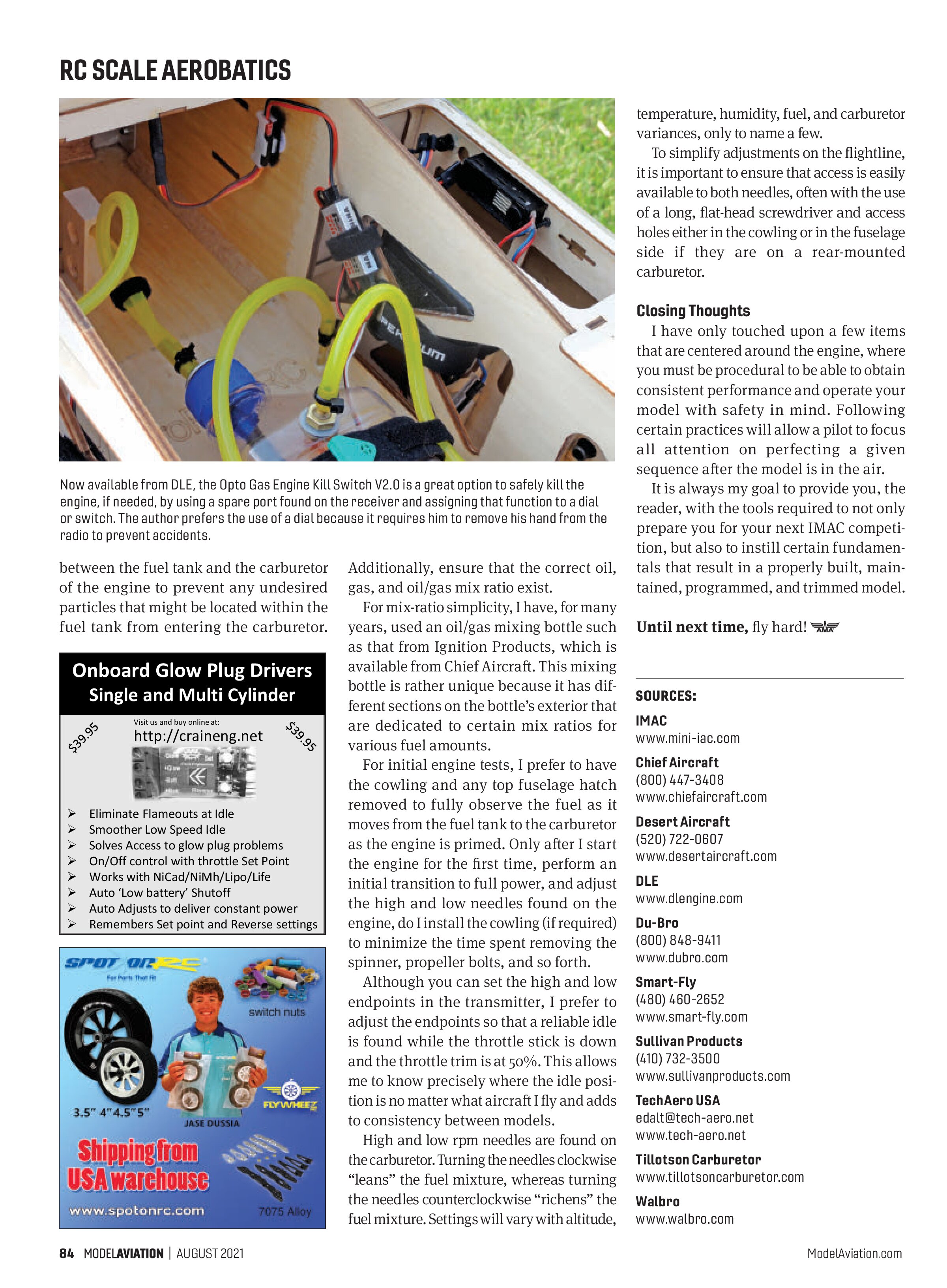
If a battery is used, two other popular units include the single-receiver Ignition Cutoff from Smart-Fly or the Opto Gas Engine Kill Switch V2.0 from DLE. All units allow a pilot to shut off the electronic ignition from the transmitter through an unused port found on the receiver. Although subtle differences exist between each option, I have used all with great success.
Getting Connected: An Overview on Plumbing
The fuel line installation and routing must be as simple as possible, with all fuel lines being gasoline resistant for a gas-powered model. Regarding the fuel tank build, it is common to have either a two- or three-line setup.
In a two-line setup, a T-fitting is used on the fuel tank’s pickup line between the connection on the tank and the carburetor to allow you to fuel and defuel the aircraft using a fuel dot. The second line is the vent line, routed to and secured to the bottom of the airplane.
The three-line setup contains a pickup line that connects directly to the carburetor, but instead of having a T-fitting as in the earlier example, a second line is connected to the tank to fuel and defuel gasoline, with a clunk on that particular line within the tank and a fuel dot on the exterior of the model. The third line is the vent, which will be routed to the bottom of the aircraft and properly secured.
Although I prefer the three-line setup because it allows me to easily fuel and defuel a tank without worrying about fuel traveling into the carburetor, both are great. Regardless, Du-Bro and Sullivan Products have a few offerings that can be considered.
Du-Bro offers Fuel Line Barbs for both 5/32-inch and 1/8-inch brass tubing. By soldering a barb on the brass fuel tubes, both inside and outside of the fuel tank, you can prevent the fuel lines from coming off of the tubes, with safety wiring on all fuel lines within the tank and outside of it. Sullivan offers Twist-Tie Clamps, which work quite well because they cannot come loose when they are properly installed.

Initial Engine Tests
Before even attempting to start the engine, ensure that a filter is used between the fuel container and where fuel enters the aircraft, as well as another filter

between the fuel tank and the carburetor of the engine to prevent any undesired particles that might be located within the fuel tank from entering the carburetor.
Additionally, ensure that the correct oil, gas, and oil/gas mix ratio exist.
For mix-ratio simplicity, I have, for many years, used an oil/gas mixing bottle such as that from Ignition Products, which is available from Chief Aircraft. This mixing bottle is rather unique because it has different sections on the bottle’s exterior that are dedicated to certain mix ratios for various fuel amounts.
For initial engine tests, I prefer to have the cowling and any top fuselage hatch removed to fully observe the fuel as it moves from the fuel tank to the carburetor as the engine is primed. Only after I start the engine for the first time, perform an initial transition to full power, and adjust the high and low needles found on the engine, do I install the cowling (if required) to minimize the time spent removing the spinner, propeller bolts, and so forth.
Although you can set the high and low endpoints in the transmitter, I prefer to adjust the endpoints so that a reliable idle is found while the throttle stick is down and the throttle trim is at 50%. This allows me to know precisely where the idle position is no matter what aircraft I fly and adds to consistency between models.
High and low rpm needles are found on the carburetor. Turning the needles clockwise “leans” the fuel mixture, whereas turning the needles counterclockwise “richens” the fuel mixture. Settings will vary with altitude, temperature, humidity, fuel, and carburetor variances, only to name a few.
To simplify adjustments on the flightline, it is important to ensure that access is easily available to both needles, often with the use of a long, flat-head screwdriver and access holes either in the cowling or in the fuselage side if they are on a rear-mounted carburetor.
Closing Thoughts
I have only touched upon a few items that are centered around the engine, where you must be procedural to be able to obtain consistent performance and operate your model with safety in mind. Following certain practices will allow a pilot to focus all attention on perfecting a given sequence after the model is in the air.
It is always my goal to provide you, the reader, with the tools required to not only prepare you for your next IMAC competition, but also to instill certain fundamentals that result in a properly built, maintained, programmed, and trimmed model.
Until next time, fly hard!
SOURCES:
IMAC
www.mini-iac.com
Chief Aircraft
(800) 447-3408
www.chiefaircraft.com
Desert Aircraft
(520) 722-0607
www.desertaircraft.com
DLE
www.dlengine.com
Du-Bro
(800) 848-9411
www.dubro.com
Smart-Fly
(480) 460-2652
www.smart-fly.com
Sullivan Products
(410) 732-3500
www.sullivanproducts.com
TechAero USA
edalt@tech-aero.net
www.tech-aero.net
Tillotson Carburetor
www.tillotsoncarburetor.com
Walbro
www.walbro.com