DISCHARGING WITH RESISTORS
By Terry Dunn | terrydunn74@gmail.com

I HAVE RECEIVED A LOT of great feedback from readers about the homemade battery discharger that I presented in my April 2021 column. It appears that many people have been using a wide variety of do-it-yourself dischargers for years. Most of them utilize an arrangement of one or more DC lightbulbs as the load.
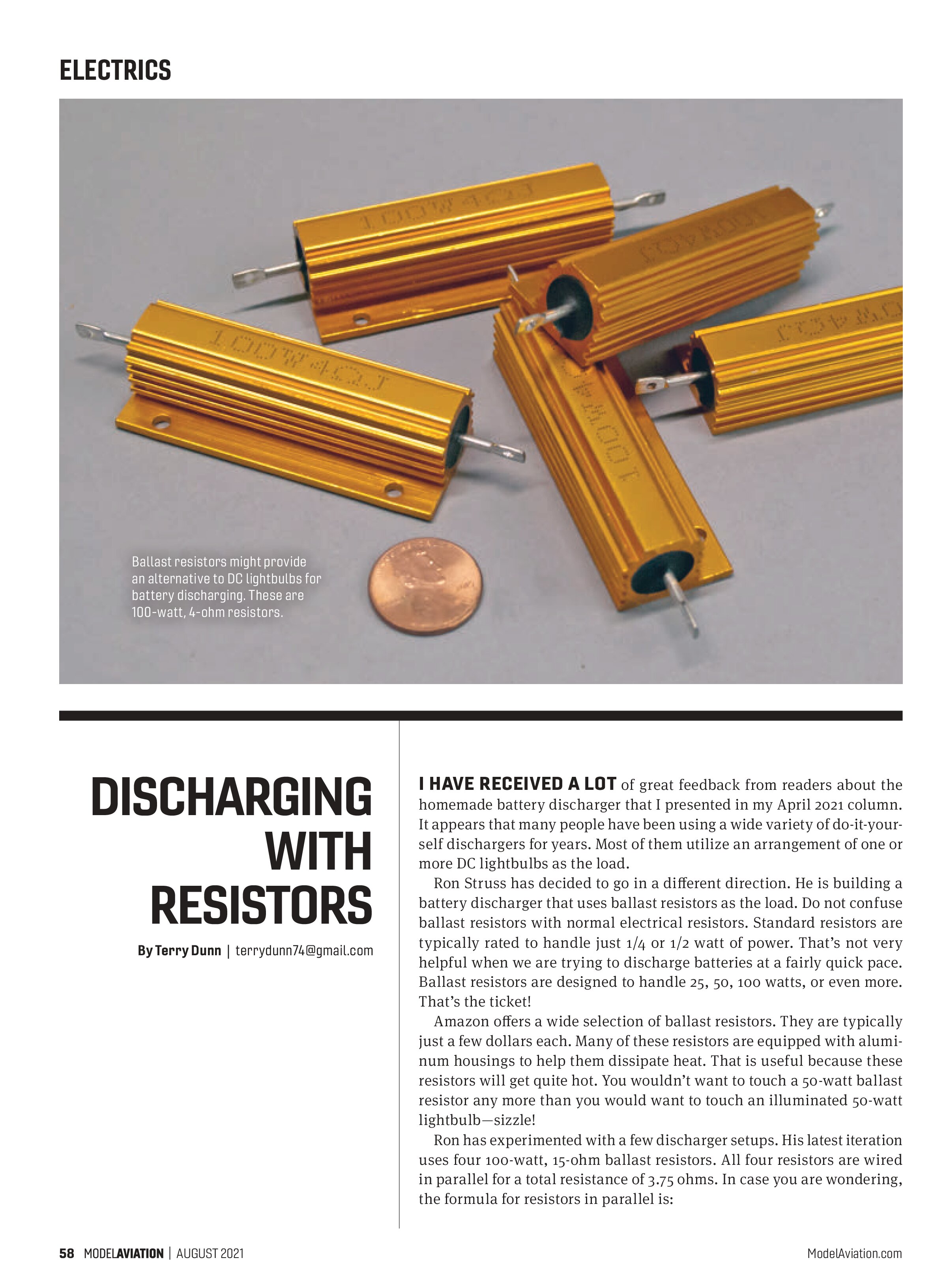
Ron Strauss has decided to go in a different direction. He is building a battery discharger that uses ballast resistors as the load. Do not confuse ballast resistors with normal electrical resistors. Standard resistors are typically rated to handle just 1/4 or 1/2 watt of power. That’s not very helpful when we are trying to discharge batteries at a fairly quick pace. Ballast resistors are designed to handle 25, 50, 100 watts, or even more. That’s the ticket!
Amazon offers a wide selection of ballast resistors. They are typically just a few dollars each. Many of these resistors are equipped with aluminum housings to help them dissipate heat. That is useful because these resistors will get quite hot. You wouldn’t want to touch a 50-watt ballast resistor any more than you would want to touch an illuminated 50-watt lightbulb—sizzle!
Ron has experimented with a few discharger setups. His latest iteration uses four 100-watt, 15-ohm ballast resistors. All four resistors are wired in parallel for a total resistance of 3.75 ohms. In case you are wondering, the formula for resistors in parallel is:
1/Rtotal = 1/R1 + 1/R2 + 1/R3 + 1/R4
For this example, we have:
1/Rtotal = 1/15 + 1/15 + 1/15 + 1/15
1/Rtotal = 4/15
1/Rtotal = .267
Rtotal = 3.75 ohms
This discharger should provide slightly lower discharge rates than my lightbulb-based discharger, which has a resistance of approximately 3 ohms, so both dischargers will deplete two-cell, three-cell, or four-cell LiPo batteries in approximately the same amount of time.
Ron is not yet ready to endorse the ballast resistor approach to battery discharging, simply because he wants to perform more testing. Even so, his idea intrigues me. I have ordered a few ballast resistors of my own with which to experiment. I will follow up here if the results are favorable.
Amazing Achievements
It’s incredible to think that an electric-powered aircraft has been flown on another planet. As I write this column, NASA’s Ingenuity helicopter has completed four successful flights on Mars. We’re talking about an environment that is less than 1% of the density of the Earth’s atmosphere. The list of engineering challenges is difficult to fathom.
This monumental achievement deserves a tribute. I checked that box by making a semiscale rendition of Ingenuity that I could fly in another harsh environment—my workshop! Unlike the actual Ingenuity, this was a quick project that I was able to bring together in roughly an hour.
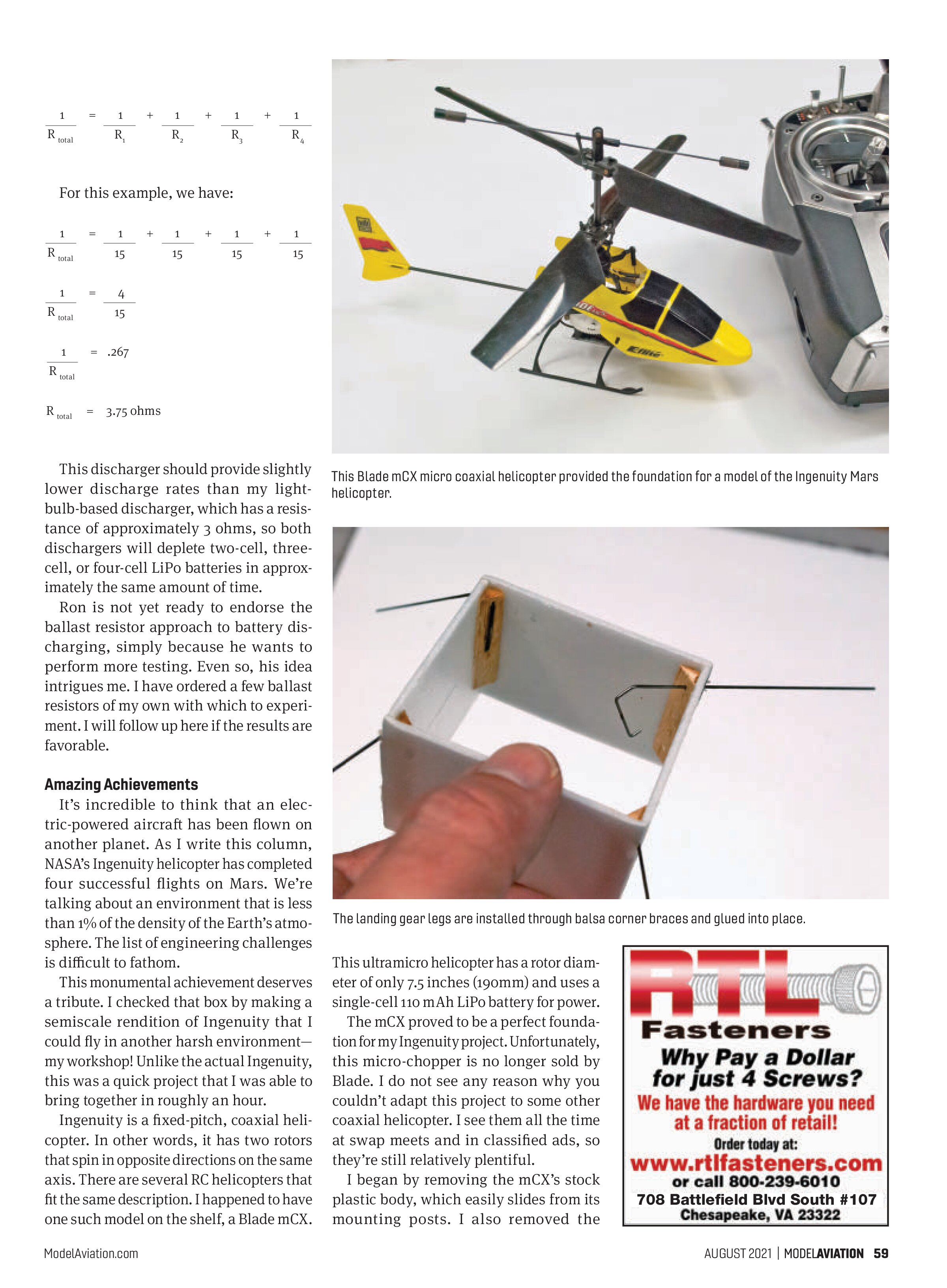
Ingenuity is a fixed-pitch, coaxial helicopter. In other words, it has two rotors that spin in opposite directions on the same axis. There are several RC helicopters that fit the same description. I happened to have one such model on the shelf, a Blade mCX.

This ultramicro helicopter has a rotor diameter of only 7.5 inches (190mm) and uses a single-cell 110 mAh LiPo battery for power.
The mCX proved to be a perfect foundation for my Ingenuity project. Unfortunately, this micro-chopper is no longer sold by Blade. I do not see any reason why you couldn’t adapt this project to some other coaxial helicopter. I see them all the time at swap meets and in classified ads, so they’re still relatively plentiful.
I began by removing the mCX’s stock plastic body, which easily slides from its mounting posts. I also removed the

tailboom, which is a purely cosmetic feature of the mCX (and any other coaxial helicopter), and is friction-fitted into the plastic frame of the helicopter. I was able to remove it just by pulling.
With the body removed, I had access to the drive system and the “brick” of the mCX. The brick is a single circuit board that houses a Spektrum-compatible receiver, two linear servos, two ESCs for the brushed motors, and gyros to help keep it all under control. You’ll find similar equipment on most ultramicro helicopters and fixed-wing models.
I used 2mm thick Depron foam to build a simple box around the brick and drive system. If you do not have Depron, I am sure that you could use any other type of sheet foam or balsa. Just be conscious of the weight. The mCX does not have much surplus lifting power.
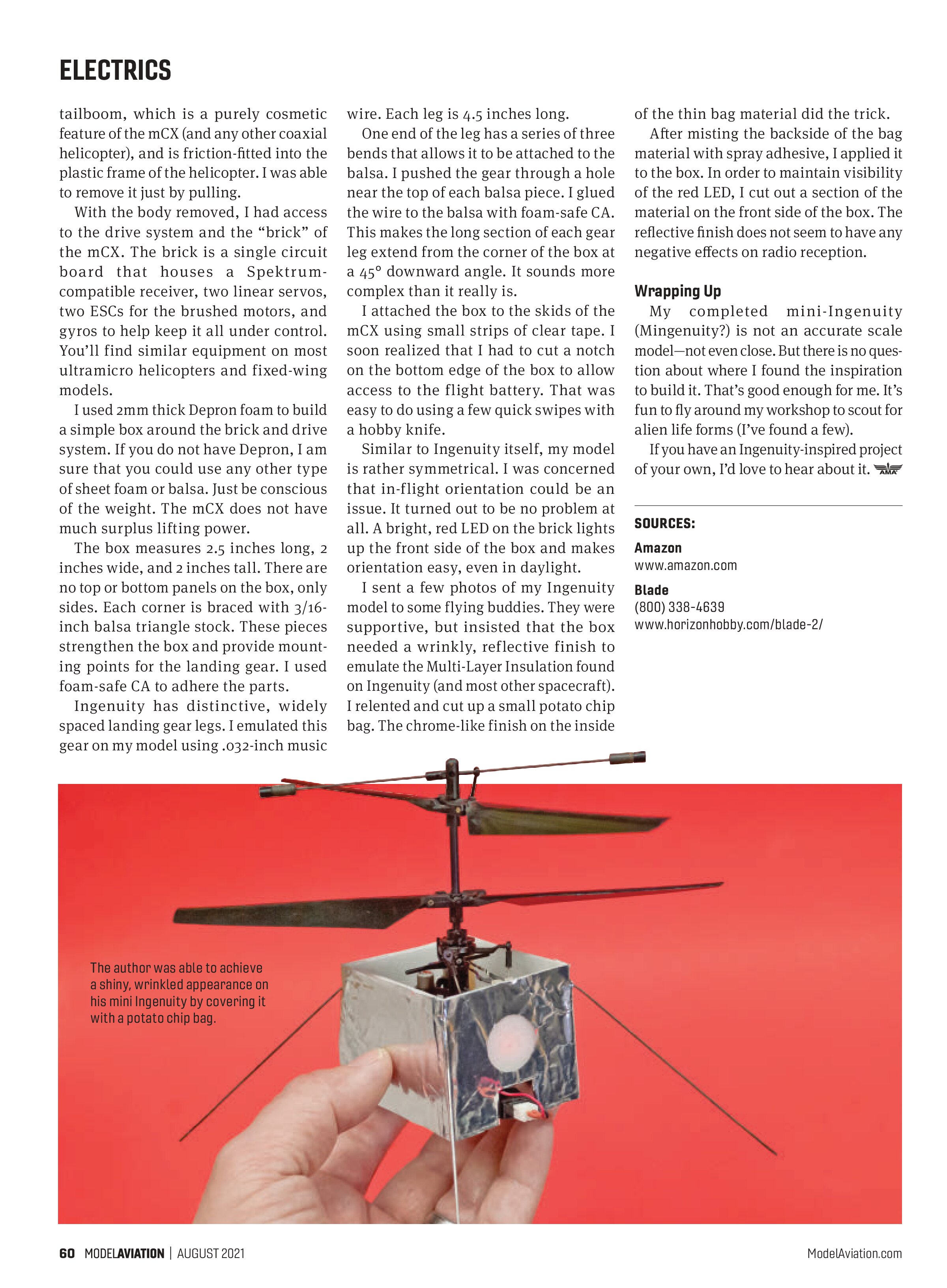
The box measures 2.5 inches long, 2 inches wide, and 2 inches tall. There are no top or bottom panels on the box, only sides. Each corner is braced with 3/16-inch balsa triangle stock. These pieces strengthen the box and provide mounting points for the landing gear. I used foam-safe CA to adhere the parts.
Ingenuity has distinctive, widely spaced landing gear legs. I emulated this gear on my model using .032-inch music wire. Each leg is 4.5 inches long. One end of the leg has a series of three bends that allows it to be attached to the balsa. I pushed the gear through a hole near the top of each balsa piece. I glued the wire to the balsa with foam-safe CA. This makes the long section of each gear leg extend from the corner of the box at a 45° downward angle. It sounds more complex than it really is.
I attached the box to the skids of the mCX using small strips of clear tape. I soon realized that I had to cut a notch on the bottom edge of the box to allow access to the flight battery. That was easy to do using a few quick swipes with a hobby knife.
Similar to Ingenuity itself, my model is rather symmetrical. I was concerned that in-flight orientation could be an issue. It turned out to be no problem at all. A bright, red LED on the brick lights up the front side of the box and makes orientation easy, even in daylight.
I sent a few photos of my Ingenuity model to some flying buddies. They were supportive, but insisted that the box needed a wrinkly, reflective finish to emulate the Multi-Layer Insulation found on Ingenuity (and most other spacecraft). I relented and cut up a small potato chip bag. The chrome-like finish on the inside of the thin bag material did the trick. After misting the backside of the bag material with spray adhesive, I applied it to the box. In order to maintain visibility of the red LED, I cut out a section of the material on the front side of the box. The reflective finish does not seem to have any negative effects on radio reception.
Wrapping Up
My completed mini-Ingenuity (Mingenuity?) is not an accurate scale model—not even close. But there is no question about where I found the inspiration to build it. That’s good enough for me. It’s fun to fly around my workshop to scout for alien life forms (I’ve found a few).
If you have an Ingenuity-inspired project of your own, I’d love to hear about it.

SOURCES:
Amazon
www.amazon.com
Blade
(800) 338-4639
www.horizonhobby.com/blade-2/