FREE FLIGHT DURATION
VINTAGE ELECTRONICS
By Louis Joyner | joynerduration@gmail.com

NO, I’M NOT REFERRING TO electronics that were used in Wakefields back in the 1950s—they didn’t exist. Those electronics were only a burning fuse to trigger the dethermalizer (DT). By the 1960s, fuses were being replaced by more accurate clockwork timers. At first, timers were used just for DT. Eventually, functions such as auto rudder and variable incidence tailplane (VIT) were added.
The German-made Seelig clockwork timers were popular. Different versions were available for gas, Towline gliders, and rubber-powered models. Production of these clockwork timers ended years ago, but used ones can sometimes be found on the internet.
The three-function Seelig F1B timer weighed 19.5 grams and was approximately 1 inch wide and 2-3/4 inches long. The most common mounting location was on the left side of the pylon near the model’s center of gravity. This allowed easy access to the built-in start button, although most people rigged a simple lever to start the timer at launch. Other popular timer locations were on top of the pylon or on the top of the fuselage in front of the wing. Some were even mounted in the tailboom slightly behind the rear peg.
The Wakefield designs of the 1950s through the 1970s are now being reconstructed for the Vintage Wakefield event. Today we have electronic timers, tracking radios, remote dethermalizers (RDT), and even GPS to fit into the model. Sometimes it can be a tight fit.
One of the vintage models that I’m building is Walt Ghio’s Shadow from the late 1970s. The original was fitted with a three-function Seelig timer mounted in the left side of the pylon. Because the model uses both auto rudder and VIT, I’ll be using the compact Simplicity timer from Alex Andriukov. It weighs 15 grams, including the start switch and 240 mAh LiPo battery. The timer includes a built-in servo to operate auto functions, RDT, and an altimeter. It will fit easily into the pylon, with plenty of room for the tracking radio.
Another model I have in the works is the late Paul Lagan’s Rasputin from 1979. The original used a prop-stop auto rudder. A pivoting lever mounted on the face of the nose block was connected to a line running back to the rudder. During the climb, the line held the rudder to the left. When the propeller stopped, the Montreal pin pushed the lever aside and dropped into the stop hole in the nose block. This released the rudder, allowing it to move to the right glide position. A fuse DT was used.

The pylon on the original Rasputin was more than 8 inches long, offering plenty of room for a Bauer standalone RDT system and a tracking radio. Instead of a separate timer, the RDT system will be used to terminate the flight at the proper time.
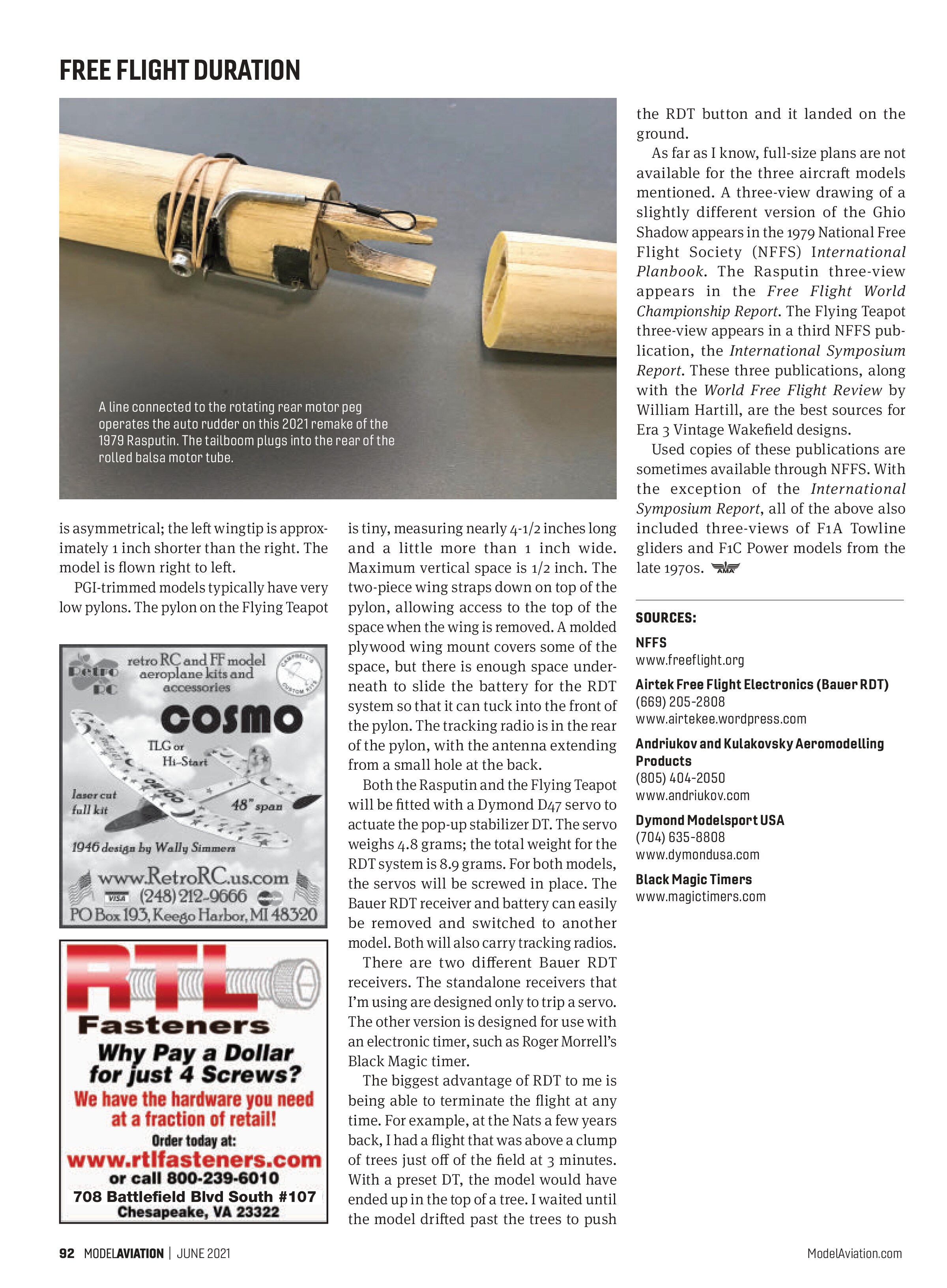
As an alternative to a prop-stop auto rudder, I’ll use the moving rear peg system that I used on a number of Wakefields back in the 1970s. The hole in the left side of the motor tube is elongated, allowing the rear peg to rotate approximately 10° to the left when the motor is wound. This pulls a line attached to the rudder to the left for the powered portion of the flight. At the end of the propeller run, a couple of size 8 rubber bands move the peg back to the right, allowing the rudder to move to the right for glide. (Rasputin was named after a popular song of the 1970s, not the Russian mystic.)
I’m also working on Jean-Claude Neglais’ Flying Teapot. This French design uses the PGI trim developed by Jean-Claude, Jean Wantzenriether, and Emile Gouverne.
No auto surfaces are used. The wing is set at a slight negative angle relative to the motor tube (1° on the Teapot). The thrustline is also set at a negative angle (3° for the Teapot). The idea is to vector the thrust through the model’s center mass to reduce the looping tendency during the power burst. The 16-to-1 aspect wing ratio

is asymmetrical; the left wingtip is approximately 1 inch shorter than the right. The model is flown right to left.
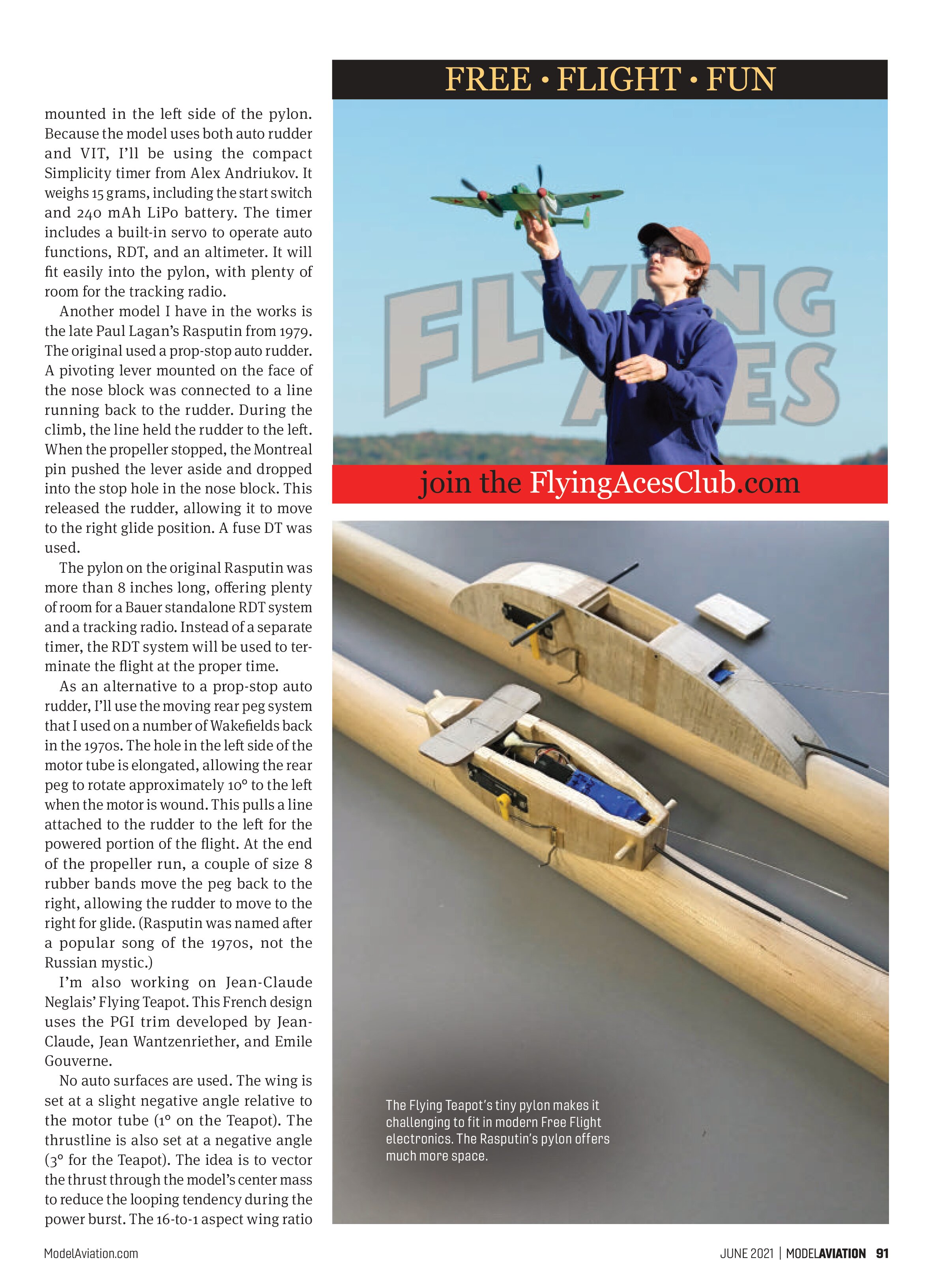
PGI-trimmed models typically have very low pylons. The pylon on the Flying Teapot is tiny, measuring nearly 4-1/2 inches long and a little more than 1 inch wide. Maximum vertical space is 1/2 inch. The two-piece wing straps down on top of the pylon, allowing access to the top of the space when the wing is removed. A molded plywood wing mount covers some of the space, but there is enough space underneath to slide the battery for the RDT system so that it can tuck into the front of the pylon. The tracking radio is in the rear of the pylon, with the antenna extending from a small hole at the back.
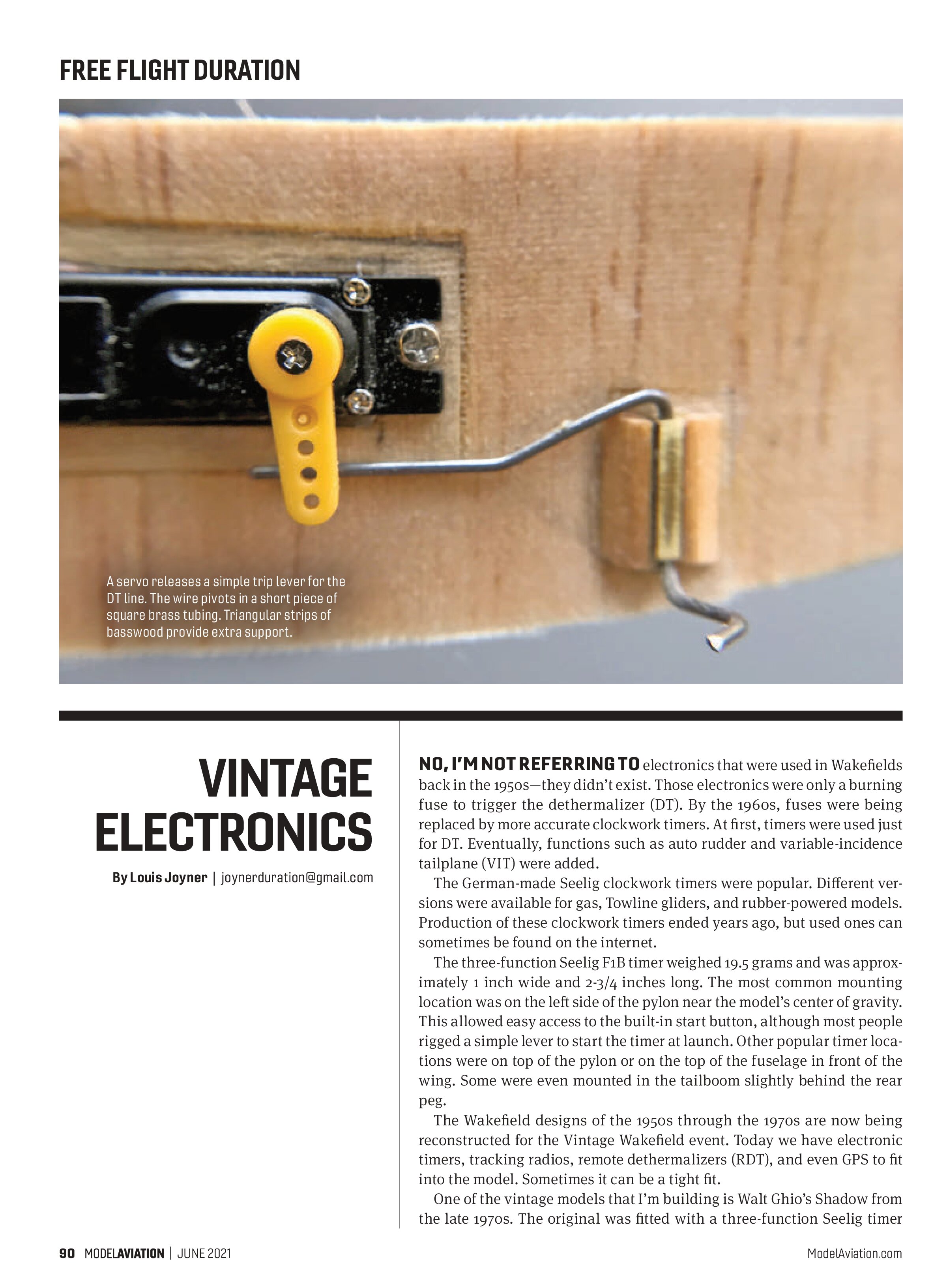
Both the Rasputin and the Flying Teapot will be fitted with a Dymond D47 servo to actuate the pop-up stabilizer DT. The servo weighs 4.8 grams; the total weight for the RDT system is 8.9 grams. For both models, the servos will be screwed in place. The Bauer RDT receiver and battery can easily be removed and switched to another model. Both will also carry tracking radios.
There are two different Bauer RDT receivers. The standalone receivers that I’m using are designed only to trip a servo. The other version is designed for use with an electronic timer, such as Roger Morrell’s Black Magic timer.
The biggest advantage of RDT to me is being able to terminate the flight at any time. For example, at the Nats a few years back, I had a flight that was above a clump of trees just off of the field at 3 minutes. With a preset DT, the model would have ended up in the top of a tree. I waited until the model drifted past the trees to push the RDT button and it landed on the ground.
As far as I know, full-size plans are not available for the three aircraft models mentioned. A three-view drawing of a slightly different version of the Ghio Shadow appears in the 1979 National Free Flight Society (NFFS) International Planbook. The Rasputin three-view appears in the Free Flight World Championship Report. The Flying Teapot three-view appears in a third NFFS publication, the International Symposium Report. These three publications, along with the World Free Flight Review by William Hartill, are the best sources for Era 3 Vintage Wakefield designs.
Used copies of these publications are sometimes available through NFFS. With the exception of the International Symposium Report, all of the above also included three-views of F1A Towline gliders and F1C Power models from the late 1970s.
SOURCES:
Airtek Free Flight Electronics (Bauer RDT)
(669) 205-2808
www.airtekee.wordpress.com
Andriukov and Kulakovsky Aeromodelling Products
(805) 404-2050
www.andriukov.com
Dymond Modelsport USA
(704) 635-8808
www.dymondusa.com
Black Magic Timers
www.magictimers.com