How to Program Heli Governor Mode
Programming throttle curves, pitch curves,
and governor mode
on ESCs
By James Wang
Photos by the author
heloeditor@gmail.com
While visiting various events and flying fields and talking with pilots who fly electric-powered helicopters, I’ve discovered that a number of them still find it challenging to program the governor mode on their ESCs. In this article, I will explain 1) The differences with using a governor mode versus simply setting up a throttle curve; 2) The principles of how the governor mode works; and 3) How to program the governor mode on Castle Creations ESCs.

Throttle Curves
Most modern RC transmitters now come standard with programmable features for RC airplanes, helicopters, and drones. Low-budget or old-fashioned airplane transmitters do not have the necessary features for helicopter flying; they do not have throttle curves and pitch curves. Throttle and pitch curves were invented in the late 1970s. JR was one of the first RC equipment manufacturers to come up with dedicated helicopter transmitters. At that time, all RC helicopters were powered by two-stroke, glow fuel-powered engines.
To match the increase in blade aerodynamic drag when the blade pitch angle is increased, the throttle curve was invented to allow the transmitter to automatically increase engine power when the pilot increases the blade pitch angle (called collective pitch). When a pilot moves the transmitter’s throttle stick, the transmitter sends a signal to both the throttle channel (usually Channel 1 or Channel 3) and the collective-pitch channel (usually Channel 6) of the receiver at the same time. The pilot must program then fine-tune the throttle curve so that the engine’s power will nearly match the rotor blade drag at all pitch angles and the rotor rpm will be nearly constant.
There are usually at least four throttle curves on a heli transmitter. In general, the Normal mode throttle curve is used for spooling up the main rotor, taking off, upright hovering, and upright forward flight. The Idle-Up 1 throttle curve, sometimes called Stunt Mode 1, is for aerobatics. The Idle-Up 2 throttle curve, or Stunt Mode 2, is for more aggressive 3D aerobatics. There is also a Throttle-Hold mode, which simply puts the engine into an idle or turns off the electric motor to allow autorotation maneuvers.
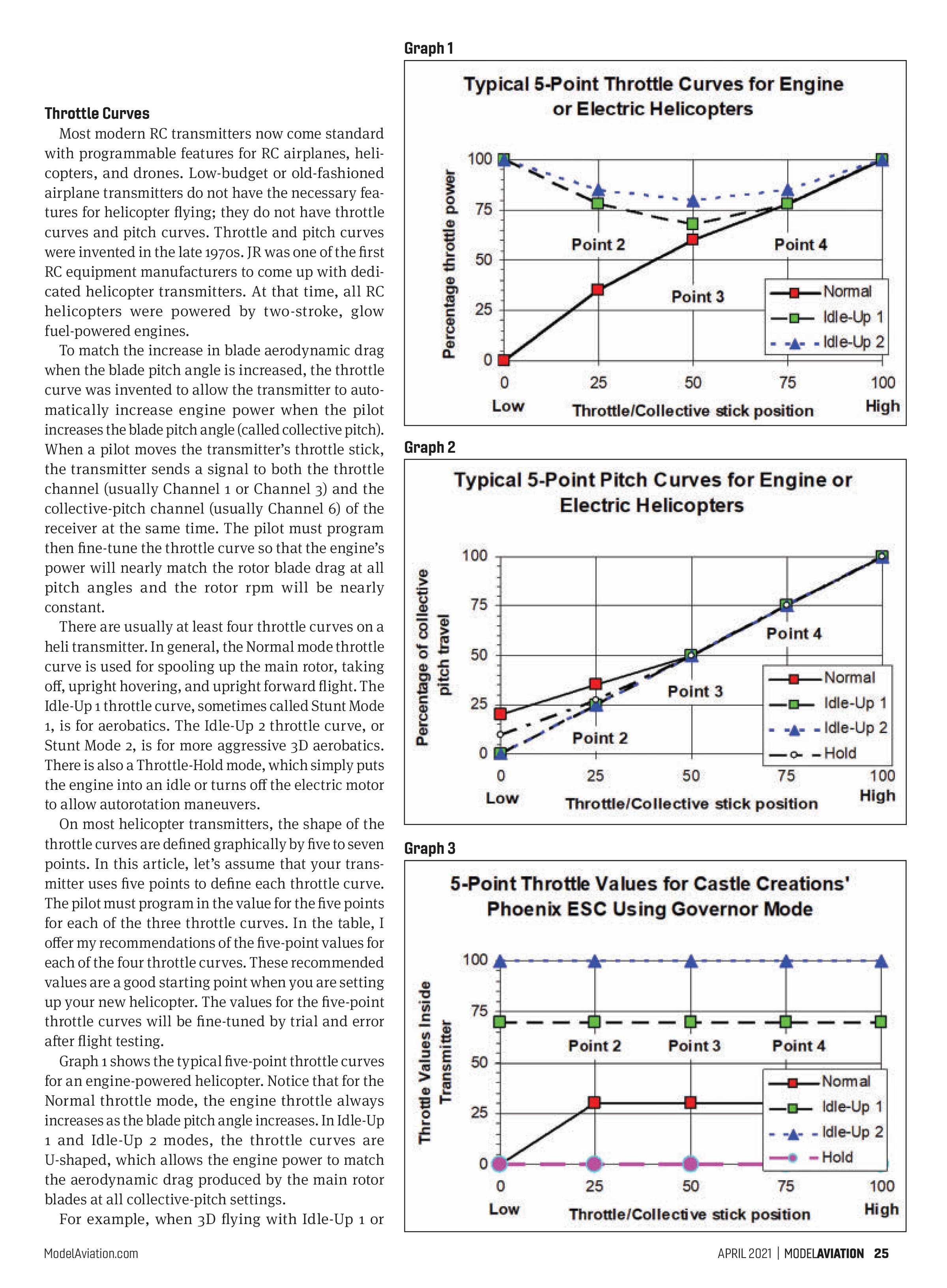
On most helicopter transmitters, the shape of the throttle curves are defined graphically by five to seven points. In this article, let’s assume that your transmitter uses five points to define each throttle curve. The pilot must program in the value for the five points for each of the three throttle curves. In the table, I offer my recommendations of the five-point values for each of the four throttle curves. These recommended values are a good starting point when you are setting up your new helicopter. The values for the five-point throttle curves will be fine-tuned by trial and error after flight testing.
Graph 1 shows the typical five-point throttle curves for an engine-powered helicopter. Notice that for the Normal throttle mode, the engine throttle always increases as the blade pitch angle increases. In Idle-Up 1 and Idle-Up 2 modes, the throttle curves are U-shaped, which allows the engine power to match the aerodynamic drag produced by the main rotor blades at all collective-pitch settings.
For example, when 3D flying with Idle-Up 1 or


curve. My recommended values for the five points for Normal mode, Idle-Up 1, Idle-Up 2, and Throttle-Hold mode are shown in Graph 2 and also in the table.
As an example, after you have performed your heli’s maiden flight, you discover that the rotor rpm at hover is too slow and the model is sluggish. To increase the hovering rotor rpm, bump up the throttle-curve values near the middle point of the Normal mode throttle curve. You would change from my recommended 0, 35, 60, 80, 100 values to 0, 45, 65, 85, 100.
There is usually no need to ever change any of the five-point pitch-curve values that are recommended in the table. For example, if you want to enlarge the collective-pitch travel range from -12° to +12°, to -14° to +14°, you would either go into your transmitter’s Endpoint or Travel Adjust pages and increase the values from -100 to +100, to -110 to +110, modify the collective-pitch travel range in your flybarless gyro setting menu, or do both. BeastX MicroBeast, Mikado VBar, Ikon Flybarless, and bavarianDEMON flybarless gyros all allow the collective-pitch travel range to be adjusted from the gyro menu.
Similarly, if you discover that the rotor rpm in Idle-Up 2 is still too slow for spirited 3D aerobatics, simply change from the recommended 100, 85, 80, 85, 100 to 100, 95, 90, 95, 100. It will take a few flights and some trial and error to fine-tune the throttle curves to achieve a nearly constant rotor speed regardless of collective-pitch changes and maneuvers.
Engine Governor
As RC helicopter technology matured in the 1990s, engine governors were developed for glow engine-powered helicopters. Engine governors are popular among advanced 3D pilots because these electronic black boxes automatically control the engine carburetor during flight to help maintain a constant engine/main rotor rpm regardless of maneuvers.
Governors automatically increase the engine power when aerodynamic loading increases and prevent the rotor from over-revving when the blade pitch angle is reduced. Engine governors use an optical or magnetic Hall effect sensor that is attached to the engine cooling fan to measure engine rpm. An electronic circuit processes the measured engine rpm and compares it to a preset rpm chosen by the pilot. If there is an error, the circuitry sends a feedback signal to the throttle servo to vary the carburetor opening. This feedback controller can hold engine rpm within +30 and -30 rpm from the desired engine rpm under most situations.
The Futaba GV-1 governor was introduced more than a decade ago and was one of the best engine governors ever made. Nowadays, because most RC helicopters are flybarless, a governor feature is built into the later versions of the previously mentioned electronic flybarless gyro units. You just have to buy an optional optical, Hall effect, or engine backplate sensor for the flybarless gyro.
Birth of the Electric Helicopter
From the 1970s to the 1990s, glow engine-powered helicopters dominated the world because two-stroke model engines were reliable and had good power-to-weight ratio. Electric-powered helicopters only became an equal performance rival to glow engine helicopters in approximately 2005, when rechargeable LiPo batteries became more reliable, more affordable, and safer.
Another catalyst toward the electric flight revolution was the rapid advancement in brushless motors and ESC performance. Today, if we just want a 5-minute flight, the power-to-weight ratio of modern electric helicopters can even exceed that of glow engine-powered models.
When collective-pitch electric helicopters were first born in the late 1980s, and models such as the Kalt Whisper and Kyosho EP Concept were being flown, pilots programmed the ESC the same way that they programmed the throttle curves for glow engines. This method worked fine, was simple and effective, and there was nothing wrong with it.
I used five-point throttle curves as shown in the previous graph 10 years ago on all of my electric helicopters. Now I recommend using five-point throttle curves only on electric helicopters that are 450-size or smaller. For bigger electric helicopters, use an ESC that has an rpm governor feature.
Differences Between Engines and Motors
One distinct advantage of electric motors over glow engines is that motors do not over-rev as much when external loading is reduced. For example, when a helicopter is in a dive and the pilot reduces the blade pitch angle to 0°, an engine will start to scream and over-rev, while a motor self-reduces the current draw and does not over-rev. It is usually easier to tune the curvature of the U-shaped throttle curve for an electric heli to achieve a constant rotor rpm for 3D flying.
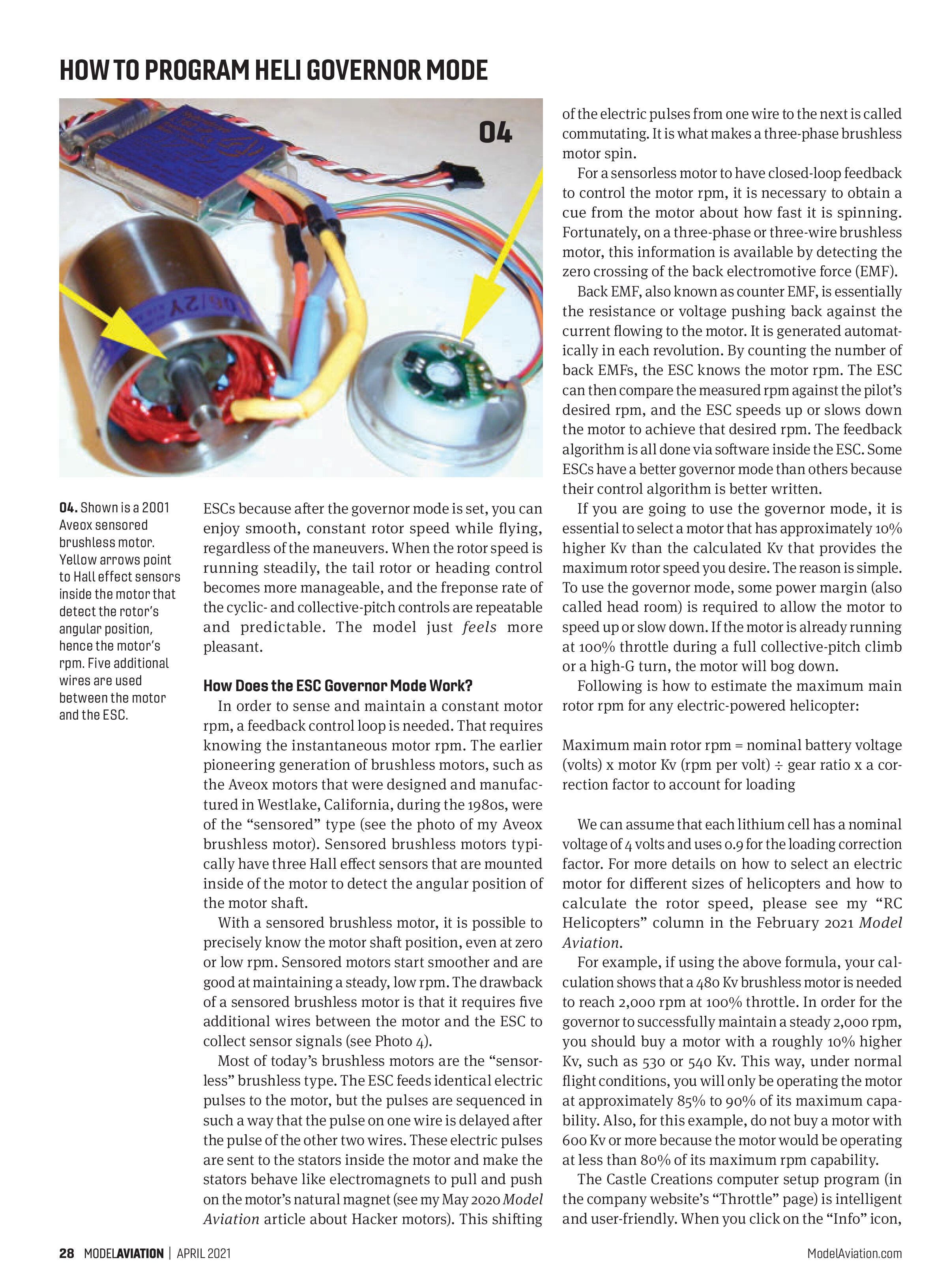
Approximately 10 years ago, to make electric helicopters mimic engine-powered ones, ESC designers added a governor feature to help the motor run at a constant rpm. At that time, the ESC software was not that intelligent, and the rotor speed was never very steady while changing loadings. Today’s high-end ESCs have an excellent governor mode. If it is properly set up, it can hold the motor rpm at +30 and -30 rpm during 3D flight.
You can become spoiled by today’s high-quality

Idle-Up 2, the main rotor blade pitch angle is usually approximately +12° to +14° at the high end of the throttle/collective stick input, producing the maximum aerodynamic drag, hence, requiring maximum engine power. At the low end of the throttle/collective stick input, the main rotor blade pitch angle is usually -12° to -14°, also producing the maximum aerodynamic drag and requiring maximum engine power.
Minimal engine power is required when the rotor blades are at 0° blade pitch angle and the throttle/collective stick is in the center position during Idle-Up 1 or Idle-Up 2. The U-shaped Idle-Up throttle curves are tweaked by trial and error by the pilot to create a constant rotor rpm regardless of what the blade pitch angle is during flight. A constant rotor speed provides more consistent and predictable control responses in all three axes to enhance 3D flying.
Why should you have two different Idle-Up throttle curves? Idle-Up 2 can be set to create a slightly higher rotor speed. For example, the Idle-Up 2 rotor rpm on a 700-size electric helicopter will be at approximately 1,900 rpm, while the Idle-Up 1 rotor speed will be close to 1,700 rpm. As you can imagine, this requires trial and error to fine-tune the U-shaped throttle curve’s shape for the rotor speed to be as steady as possible.
Pitch Curves
There is also a matching pitch curve for each throttle

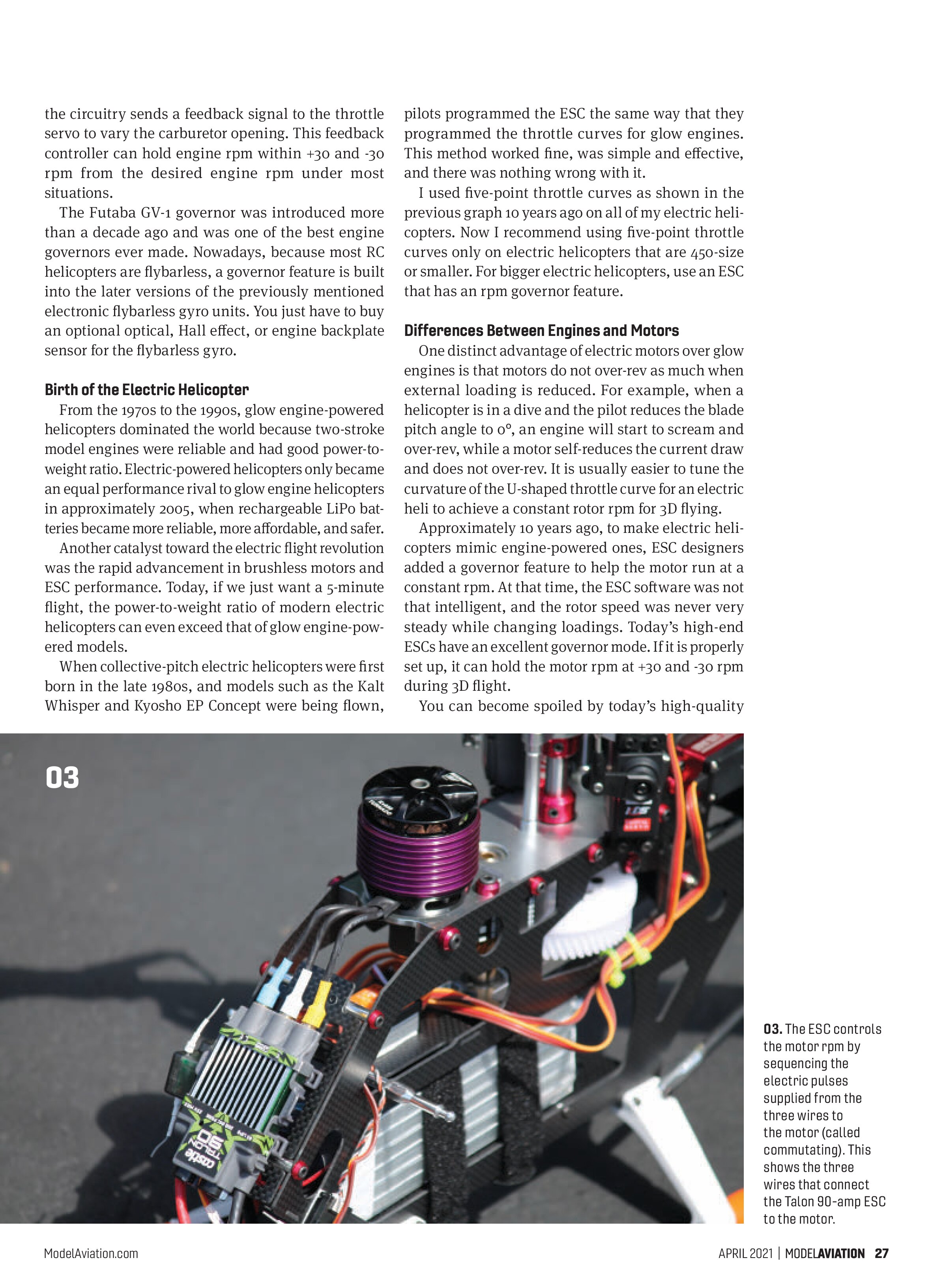
of the electric pulses from one wire to the next is called commutating. It is what makes a three-phase brushless motor spin.
For a sensorless motor to have closed-loop feedback to control the motor rpm, it is necessary to obtain a cue from the motor about how fast it is spinning. Fortunately, on a three-phase or three-wire brushless motor, this information is available by detecting the zero crossing of the back electromotive force (EMF).
Back EMF, also known as counter EMF, is essentially the resistance or voltage pushing back against the current flowing to the motor. It is generated automatically in each revolution. By counting the number of back EMFs, the ESC knows the motor rpm. The ESC can then compare the measured rpm against the pilot’s desired rpm, and the ESC speeds up or slows down the motor to achieve that desired rpm. The feedback algorithm is all done via software inside the ESC. Some ESCs have a better governor mode than others because their control algorithm is better written.
If you are going to use the governor mode, it is essential to select a motor that has approximately 10% higher Kv than the calculated Kv that provides the maximum rotor speed you desire. The reason is simple. To use the governor mode, some power margin (also called head room) is required to allow the motor to speed up or slow down. If the motor is already running at 100% throttle during a full collective-pitch climb or a high-G turn, the motor will bog down.
Following is how to estimate the maximum main rotor rpm for any electric-powered helicopter:
Maximum main rotor rpm = nominal battery voltage (volts) x motor Kv (rpm per volt) ÷ gear ratio x a correction factor to account for loading
We can assume that each lithium cell has a nominal voltage of 4 volts and uses 0.9 for the loading correction factor. For more details on how to select an electric motor for different sizes of helicopters and how to calculate the rotor speed, please see my “RC Helicopters” column in the February 2021 Model Aviation.
For example, if using the above formula, your calculation shows that a 480 Kv brushless motor is needed to reach 2,000 rpm at 100% throttle. In order for the governor to successfully maintain a steady 2,000 rpm, you should buy a motor with a roughly 10% higher Kv, such as 530 or 540 Kv. This way, under normal flight conditions, you will only be operating the motor at approximately 85% to 90% of its maximum capability. Also, for this example, do not buy a motor with 600 Kv or more because the motor would be operating at less than 80% of its maximum rpm capability.
The Castle Creations computer setup program (in the company website’s “Throttle” page) is intelligent and user-friendly. When you click on the “Info” icon, it tells you what throttle percentage range the ESC is using to achieve the governing rotor speed. The Castle Creations menu will also advise whether or not the motor and rotor speed you have chosen are good choices.
Programming Castle Creations ESC Governor Mode
I recommend always investing in the highest quality and name-brand ESC, such as Castle Creations, Hobbywing, Kontronik, Scorpion, YGE, etc. I use the first three ESC brands routinely and they all work reliably. The governor mode’s motor rpm is set in the transmitter by programming a flat line for throttle curves.
I will use the Castle Creations ESC as an example to explain ESC programming. Castle Creations is one of the top names and happens to be one of the pioneers in electric flight. The company was founded by Patrick del Castillo, who worked in the American aerospace industry before 2001. Patrick began designing ESCs in the late 1990s because he desired a lightweight, technologically advanced ESC for his personal flying. He created his first ESC in 1997. Realizing that other modelers wanted a similar choice, he and his wife, Brenda, began Castle Creations.
To use the Castle computer setup software, it is necessary to buy an optional Castle Link. This little dongle connects between the ESC’s throttle cable and the USB port on a computer. Sometimes the Castle ESC comes with a coupon for a free Castle Link. The software is downloaded from the Castle Creations website (see “Sources” for contact information). There is also a nice PDF article on the website detailing how to program the governor mode for helicopters. I recommend reading that too.
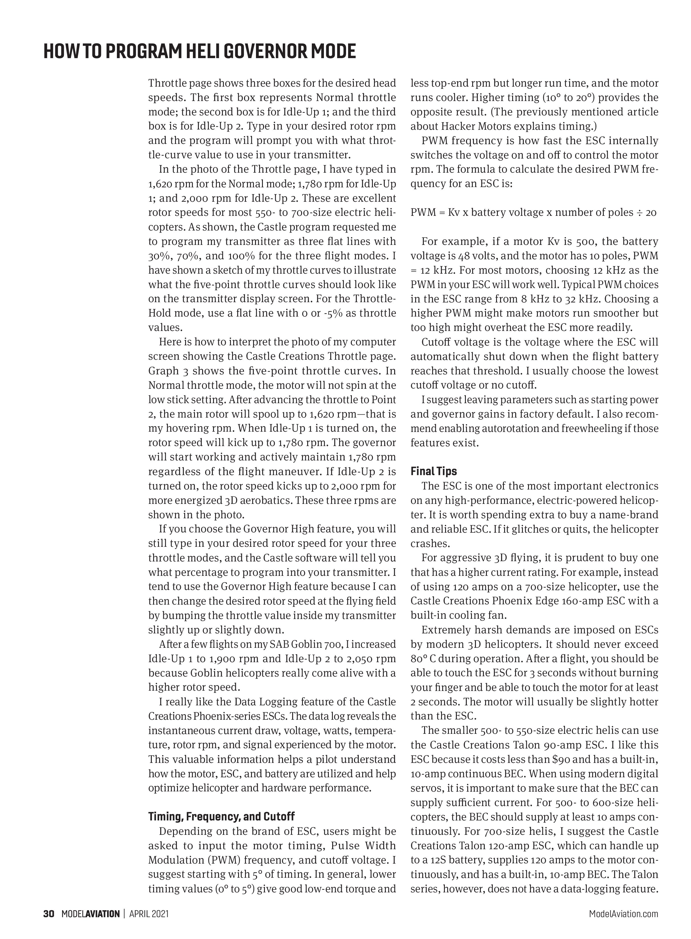
The most important page in the Castle Creations setup tool is the Throttle page. First, you need to choose either Governor High or Set RPM then enter your battery voltage. Click on Motor and Gearing to enter the helicopter model gear ratio and the number of magnetic poles for your particular motor. Just Google your motor’s brand and model number to find out the number of poles. It’s usually 8 or 10.
When using Set RPM, you choose the rotor speed and the Castle software defines what percentage to program into your transmitter. The bottom of the


Throttle page shows three boxes for the desired head speeds. The first box represents Normal throttle mode; the second box is for Idle-Up 1; and the third box is for Idle-Up 2. Type in your desired rotor rpm and the program will prompt you with what throttle-curve value to use in your transmitter.
In the photo of the Throttle page, I have typed in 1,620 rpm for the Normal mode; 1,780 rpm for Idle-Up 1; and 2,000 rpm for Idle-Up 2. These are excellent rotor speeds for most 550- to 700-size electric helicopters. As shown, the Castle program requested me to program my transmitter as three flat lines with 30%, 70%, and 100% for the three flight modes. I have shown a sketch of my throttle curves to illustrate what the five-point throttle curves should look like on the transmitter display screen. For the Throttle-Hold mode, use a flat line with 0 or -5% as throttle values.
Here is how to interpret the photo of my computer screen showing the Castle Creations Throttle page. Graph 3 shows the five-point throttle curves. In Normal throttle mode, the motor will not spin at the low stick setting. After advancing the throttle to Point 2, the main rotor will spool up to 1,620 rpm—that is my hovering rpm. When Idle-Up 1 is turned on, the rotor speed will kick up to 1,780 rpm. The governor will start working and actively maintain 1,780 rpm regardless of the flight maneuver. If Idle-Up 2 is turned on, the rotor speed kicks up to 2,000 rpm for more energized 3D aerobatics. These three rpms are shown in the photo.
If you choose the Governor High feature, you will still type in your desired rotor speed for your three throttle modes, and the Castle software will tell you what percentage to program into your transmitter. I tend to use the Governor High feature because I can then change the desired rotor speed at the flying field by bumping the throttle value inside my transmitter slightly up or slightly down.
After a few flights on my SAB Goblin 700, I increased Idle-Up 1 to 1,900 rpm and Idle-Up 2 to 2,050 rpm because Goblin helicopters really come alive with a higher rotor speed.
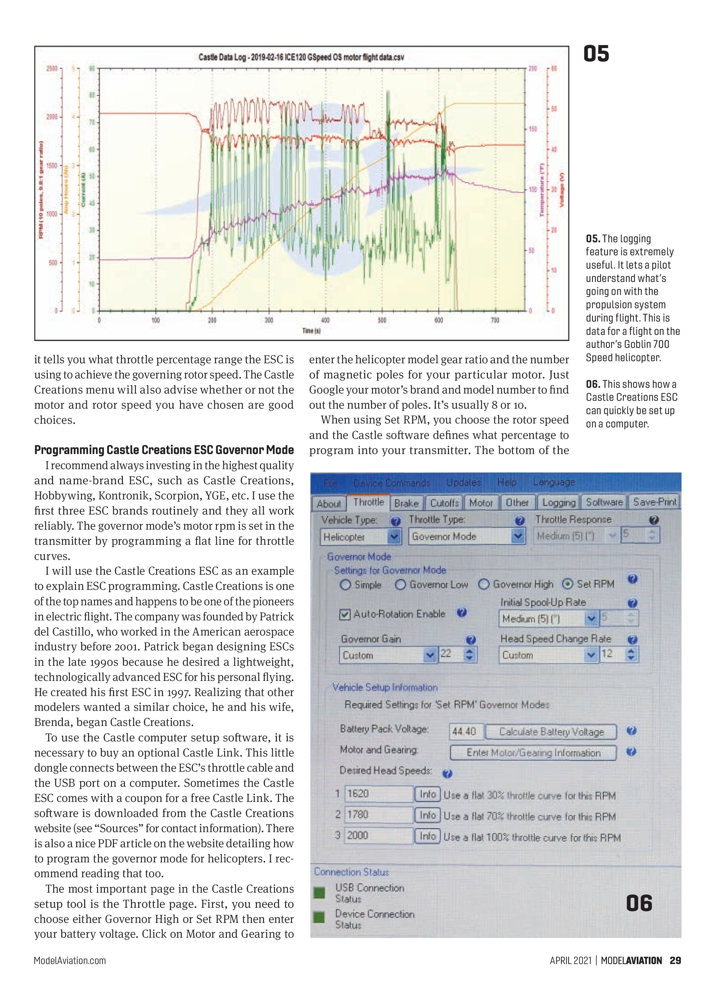
I really like the Data Logging feature of the Castle Creations Phoenix-series ESCs. The data log reveals the instantaneous current draw, voltage, watts, temperature, rotor rpm, and signal experienced by the motor. This valuable information helps a pilot understand how the motor, ESC, and battery are utilized and help optimize helicopter and hardware performance.
Timing, Frequency, and Cutoff
Depending on the brand of ESC, users might be asked to input the motor timing, Pulse Width Modulation (PWM) frequency, and cutoff voltage. I suggest starting with 5° of timing. In general, lower timing values (0° to 5°) give good low-end torque and less top-end rpm but longer run time, and the motor runs cooler. Higher timing (10° to 20°) provides the opposite result. (The previously mentioned article about Hacker Motors explains timing.)
PWM frequency is how fast the ESC internally switches the voltage on and off to control the motor rpm. The formula to calculate the desired PWM frequency for an ESC is:
PWM = Kv x battery voltage x number of poles ÷ 20
For example, if a motor Kv is 500, the battery voltage is 48 volts, and the motor has 10 poles, PWM = 12 kHz. For most motors, choosing 12 kHz as the PWM in your ESC will work well. Typical PWM choices in the ESC range from 8 kHz to 32 kHz. Choosing a higher PWM might make motors run smoother but too high might overheat the ESC more readily.
Cutoff voltage is the voltage where the ESC will automatically shut down when the flight battery reaches that threshold. I usually choose the lowest cutoff voltage or no cutoff.
I suggest leaving parameters such as starting power and governor gains in factory default. I also recommend enabling autorotation and freewheeling if those features exist.
Final Tips
The ESC is one of the most important electronics on any high-performance, electric-powered helicopter. It is worth spending extra to buy a name-brand and reliable ESC. If it glitches or quits, the helicopter crashes.
For aggressive 3D flying, it is prudent to buy one that has a higher current rating. For example, instead of using 120 amps on a 700-size helicopter, use the Castle Creations Phoenix Edge 160-amp ESC with a built-in cooling fan.
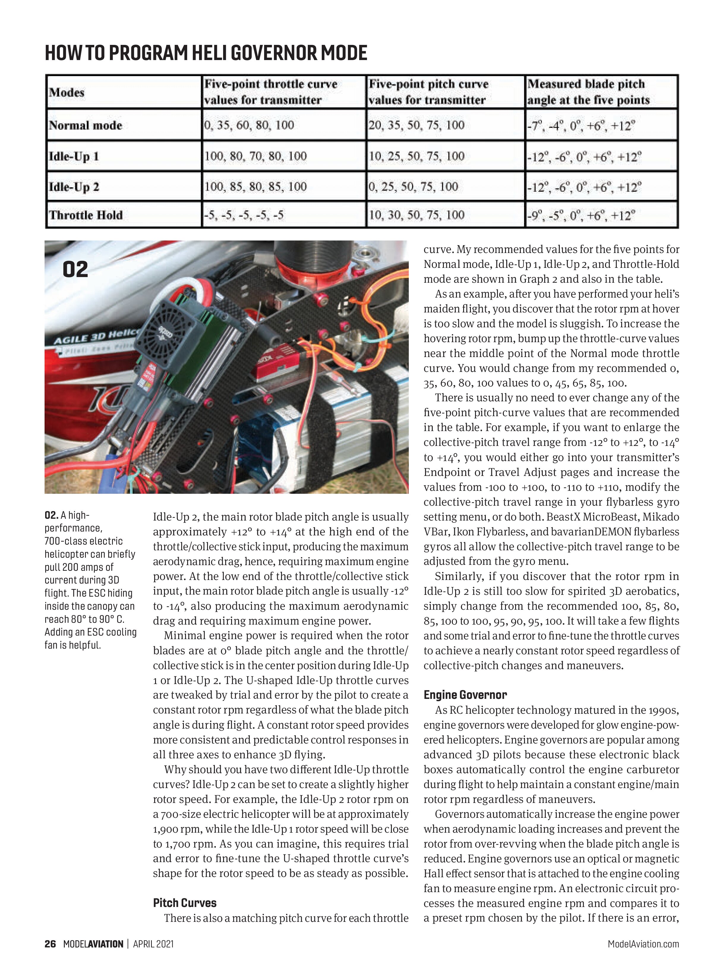
Extremely harsh demands are imposed on ESCs by modern 3D helicopters. It should never exceed 80° C during operation. After a flight, you should be able to touch the ESC for 3 seconds without burning your finger and be able to touch the motor for at least 2 seconds. The motor will usually be slightly hotter than the ESC.
The smaller 500- to 550-size electric helis can use the Castle Creations Talon 90-amp ESC. I like this ESC because it costs less than $90 and has a built-in, 10-amp continuous BEC. When using modern digital servos, it is important to make sure that the BEC can supply sufficient current. For 500- to 600-size helicopters, the BEC should supply at least 10 amps continuously. For 700-size helis, I suggest the Castle Creations Talon 120-amp ESC, which can handle up to a 12S battery, supplies 120 amps to the motor continuously, and has a built-in, 10-amp BEC. The Talon series, however, does not have a data-logging feature.
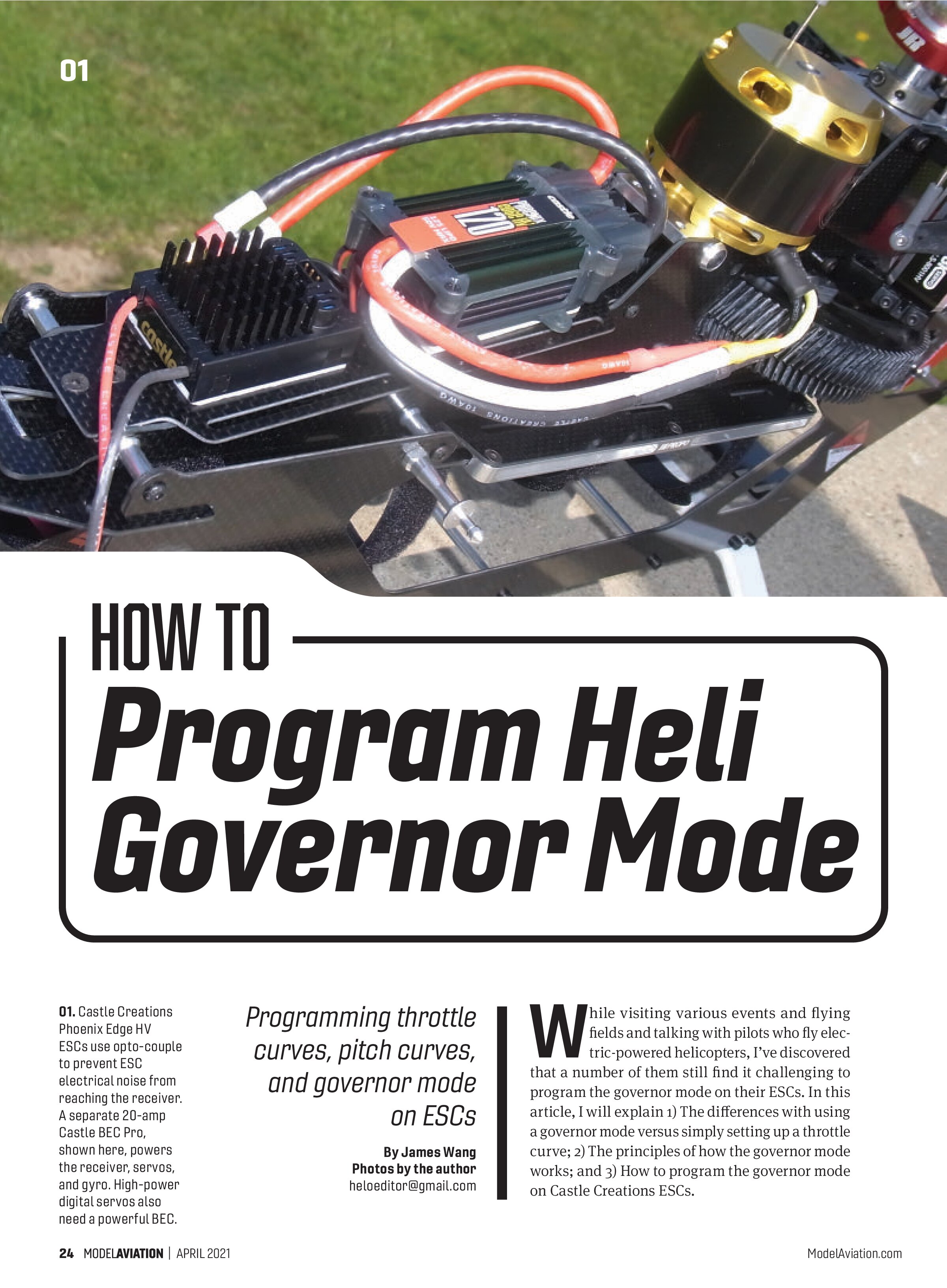
The Castle Creations Phoenix Edge 120-amp and 160-amp high-voltage ESCs use opto-couple to prevent electric noise from passing from the ESC to the receiver, so they do not have a built-in BEC. It is necessary to buy a separate BEC, such as the Castle Creations 20-amp Pro BEC. If high-voltage servos are used, you can power the servos directly by a separate 2S 2,000 mAh LiPo battery. I recommend adding an ESC cooling fan if the ESC and the fan fit inside the helicopter canopy. Only with sufficient ventilation can the ESC deliver the continuous current rating as advertised.
Instead of using the governor feature from the ESC, many modern flybarless controllers have an rpm governor feature. Newer ESCs can supply rpm information to the electronic flybarless controller, which does an equally good job of maintaining a constant rotor speed. The advantage is that the feedback control algorithm can link yaw stabilization with rpm governing.
Some Futaba, Spektrum, and Mikado VControl transmitters can even display the rotor rpm, battery voltage, and current draw by receiving signals beamed from the ESC through the receiver. This valuable information helps fine-tune the helicopter’s performance at the field.
Try keeping the wire length between the ESC and the motor as short as possible. Keep the receiver and gyro as far away as possible from the ESC, motor, and motor wires. Use high-quality, gold-plated connectors between the ESC and motor wires. Always use high-quality, large-diameter connectors for the ESC and battery.
It is extremely important to properly solder the connectors to the ESC battery and motor leads. A common culprit of crashes is cold soldering, which causes the connector to fall off of the wire during flight. The wires and soldering joint can become hot during flight, and poor soldering will open up because of vibration or stress.
An alternative is to use Supra X solderless connectors by RCProPlus. They are more expensive but high quality and can handle 230 amps. Always think of safety when building a helicopter.
See you next time.
SOURCES:
Castle Creations
(913) 390-6939
https://home.castlecreations.com
Hobbywing
fae_air@hobbywing.com
www.hobbywing.com
Kontronik
info @ kontronik.com
www.kontronik.com
Scorpion Power System
support@spihk.com
www.scorpionsystem.com
Futaba
(256) 461-9399, ext. 8
www.futabausa.com
RCProPlus
www.rcproplus.com
BeastX
info@beastx.com
www.beastx.com
Ikon Flybarless
(877) 439-4354
www.ikonflybarless.com
bavarianDEMON
info@bavariandemon.com
www.bavariandemon.com
Mikado Helicopters
(844) 4-MIKADO
www.shop.mikadousa.com
SAB Goblin Helicopters
support@goblin-helicopter.com
www.goblin-helicopter.com