RC SCALE AEROBATICS
ROUTINES FOR AIRFRAME CONFIDENCE
By John Glezellis | jglezellis@gmail.com

I RECENTLY COMPLETED the first flight on one of my 35cc aerobatic airplanes and had some time to reflect on not only that flight and the events leading up to it, but also on the amount of effort that is required to maintain an aircraft throughout the course of its lifetime. Whether I build my own aircraft or purchase one that has been already been built and/or flown, I follow the same sequence when it comes to a final inspection before the first flight.
To have consistency in competition, you must have complete confidence in your airplane. Failures can occur for a number of reasons, and although some cannot be prevented, such as a nonfunctional ignition module, you can take every possible action to minimize the likelihood that a failure will happen.
In this column, I will touch upon routine practices that you should undergo in an effort to have confidence in your airframe (in a mechanical sense) so that you can focus on perfecting that next International Miniature Aerobatic Club (IMAC) maneuver.
Without further hesitation, let’s get started!
The Maiden Flight
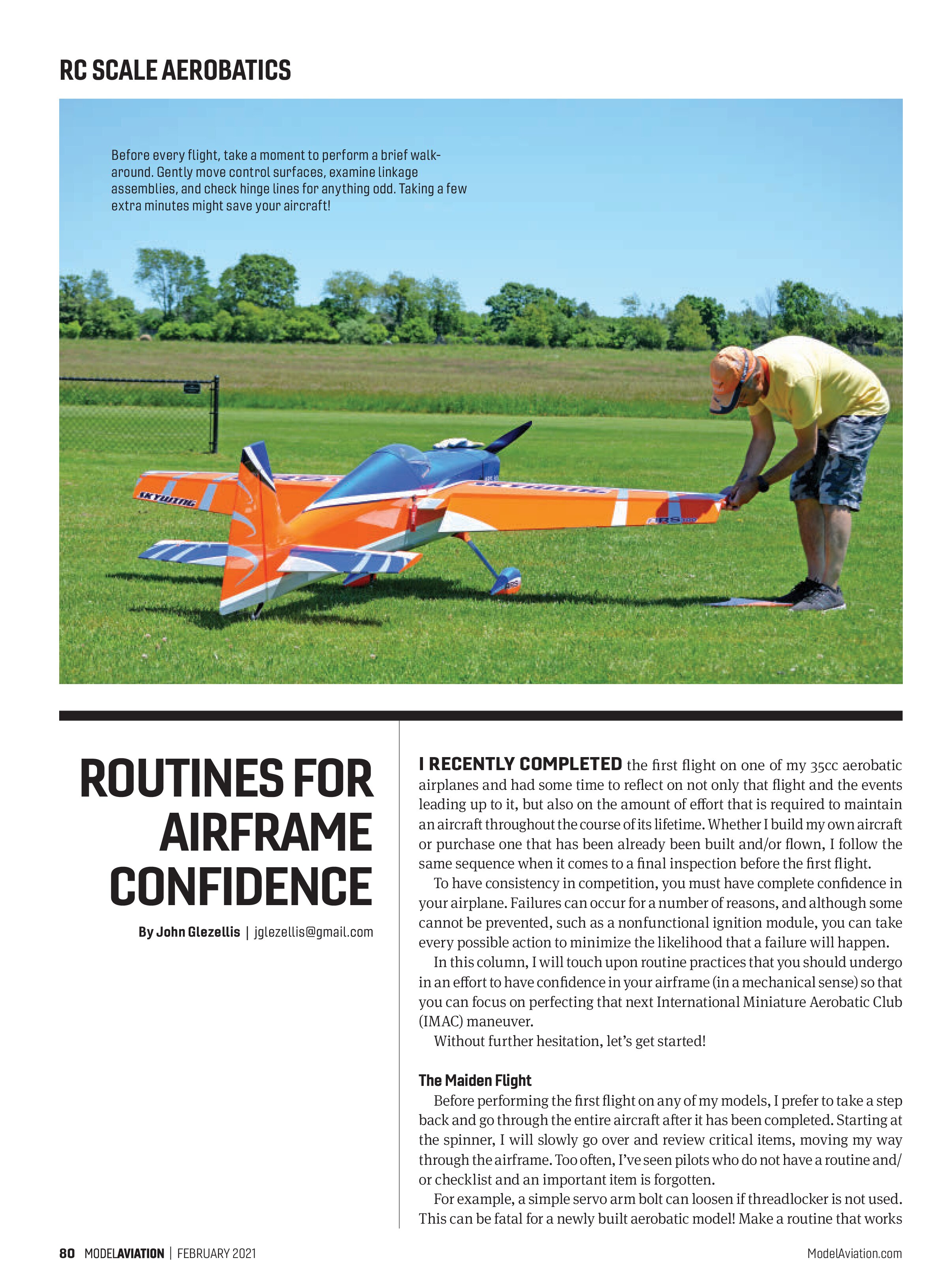
Before performing the first flight on any of my models, I prefer to take a step back and go through the entire aircraft after it has been completed. Starting at the spinner, I will slowly go over and review critical items, moving my way through the airframe. Too often, I’ve seen pilots who do not have a routine and/or checklist and an important item is forgotten.
For example, a simple servo arm bolt can loosen if threadlocker is not used. This can be fatal for a newly built aerobatic model! Make a routine that works for you and apply the same structure to all future aircraft that you decide to build or purchase.
During the preflight inspection, not all items can easily be examined. For instance, some will be hidden after the airplane is assembled, such as servo extension connections under a hatch. For instances like this, I use servo connector clips for all connections because they are installed within the airframe. I often apply a bead of silicone adhesive on the rear portion of the connector where each wire is inserted to prevent it from disconnecting.
For items that are hidden and difficult to reach in the aircraft, keep a written record of what actions were performed. Doing so will eliminate questions later about what was already completed.
In addition to hidden extension connections that cannot be accessed without removing a servo, mixing adhesives always presents a slight unknown element because you must complete this with utmost precision to obtain the desired bond strength. When mixing a two-part epoxy, use a high-precision postal scale and measure the weight of each part in grams.
Remember that not all epoxies are created equal! Some require a different ratio of resin-to-hardener, so always read the instructions provided by the adhesive manufacturer! Whenever I mix epoxy, I keep the mixing cup that was used to ensure that the adhesive cures as desired.
All loose wiring within the aircraft must be secured because, over time, wires can contact or chafe on another component. In recent years, many manufacturers of high-quality ARF model aircraft have used a mix of plywood parts that are laminated with carbon fiber. Although the result is a lightweight and rigid airplane, the corners of the carbon-fiber-laminated parts could be coarse. Wherever a delicate wire is, ensure that the area it is secured to is smooth and prepare the surface accordingly. Examples include lightly sanding a rough and uneven surface or applying a silicone adhesive.
Check the fuel tank for leaks before it is installed in the aircraft. I rinse all of my tanks with water to clear them of any debris from the manufacturer and also fill them with water and block all lines to check for leaks. Apply a small amount of pressure to the tank and observe whether any leaks are noted.
I prefer using Du-Bro tanks, even if a different brand is supplied by the manufacturer. The reason is quite simple—spares! In my field box, I keep a few spare items such as propeller bolts, aircraft assembly bolts, fuel dots, and, yes, gasoline stoppers and hardware for my fuel tanks. By using one tank brand, you can simplify all spare parts that you might need to bring to the field or competition flying site.
Because I am now on an engine-related topic, some manufacturers actually supply torque specifications with their engines. Desert Aircraft and its DA-35 engine is one example:
- Spark plug: CM-6; 10 mm; 90 inch-pounds
- Steel propeller bolts: M4x; 40 mm; 65 inch-pounds
- Aluminum carburetor mount bolts: M5 x 55 mm; 50 inch-pounds
I recommend purchasing a torque wrench to take any guesswork out of the equation concerning whether or not a spark plug or bolt was properly fastened. Be confident that all of the critical items are secure! Gasoline engines vibrate and, over time, will take their toll on an airframe and the components found within. Ensure that all metal-to-metal connections have threadlocker applied and that all controls move freely and in the proper direction.
For liquid threadlocker, I prefer Zap medium-strength blue threadlocker. I have also used Loctite 248 paste, depending on the application, because it will not drip overhead, such as when you are trying to tighten a servo arm bolt that might be on the underside of a wing panel.
Remember, a medium-locking strength of threadlocker only requires a hand tool to unthread it, whereas a high-locking strength will require heat and a hand tool to unthread. I use a medium-locking strength threadlocker on all of my model airplanes.
Routine Maintenance
After the first few flights have been completed, go through the entire airframe. Propeller, engine, muffler, and servo arm bolts could loosen. Fuel tubing might contact a hot area found on the engine. The cowling could loosen, or a servo extension might contact a sharp area found within the airframe.

Inspections should not stop here! In fact, throughout the flying season, I bring my competition model into my workshop after roughly every five flying sessions for an extensive inspection that is similar to the one performed before the maiden flight.
Final Thoughts
I have reviewed a few important areas that you should examine not only when preparing for an airframe’s maiden flight, but also when routine maintenance is required. Always remember that a few extra minutes spent on the ground—as described with the servo arm bolt example—can be the difference between a doomed or successful flight.
Always remember to learn from each experience and don’t hesitate to ask for assistance. Chances are that if you have experienced a problematic area, someone else at the flying field or competition flying site has as well!
Until next time, fly hard!

SOURCES:
Desert Aircraft
(520) 722-0607
www.desertaircraft.com
Du-Bro
(800) 848-9411
www.dubro.com
IMAC
www.mini-iac.org
Loctite
(800) 624-7767
www.loctite.com
Spektrum RC
(800) 338-4639
www.spektrumrc.com
Zap Glue
www.zapglue.com