CHOOSING A DIFFERENT MOTOR KV AND CALCULATING ROTOR RPM
By James Wang | heloeditor@gmail.com

CHOOSING A DIFFERENT main rotor rpm can have a big effect on flight endurance. A higher main rotor rpm yields shorter flights because as the blades spin faster, the rotor aerodynamic drag increases in proportion to the square of the velocity that the airfoil sees. The more drag the airfoil sees, the more power that is required from the electric motor. If you want longer flight times, use a lower rotor rpm. If you want to perform crisper 3D maneuvers, using a higher rotor speed helps give more authoritative collective/thrust response and more cyclic control changes per second.
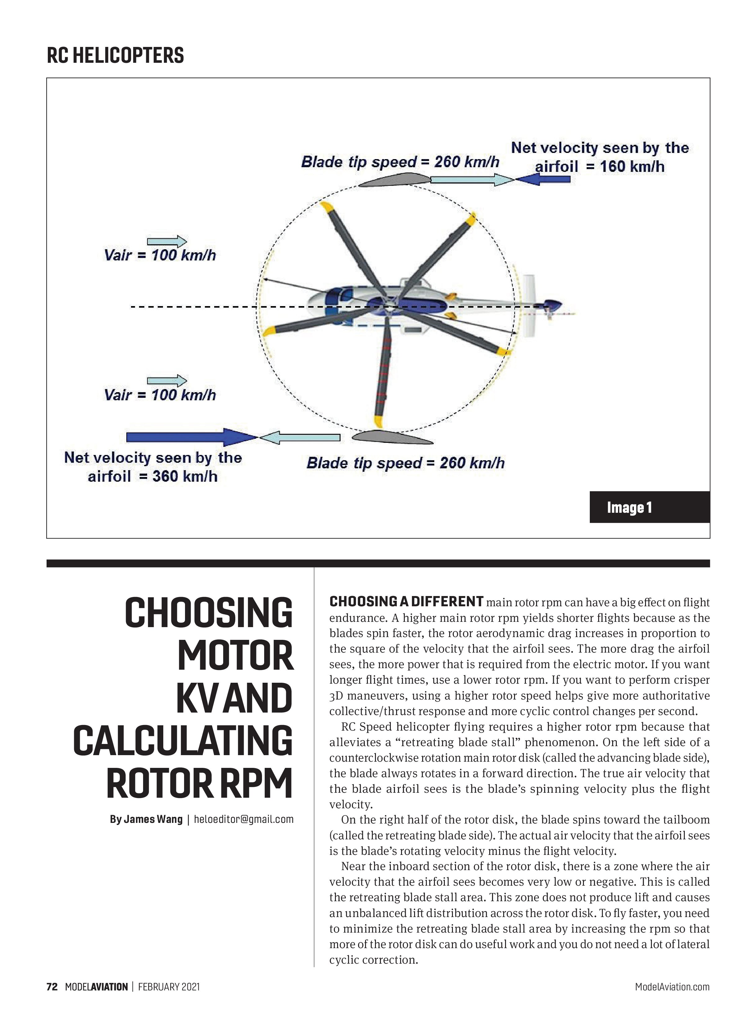
RC Speed helicopter flying requires a higher rotor rpm because that alleviates a “retreating blade stall” phenomenon. On the left side of a counterclockwise rotation main rotor disk (called the advancing blade side), the blade always rotates in a forward direction. The true air velocity that the blade airfoil sees is the blade’s spinning velocity plus the flight velocity.
On the right half of the rotor disk, the blade spins toward the tailboom (called the retreating blade side). The actual air velocity that the airfoil sees is the blade’s rotating velocity minus the flight velocity.
Near the inboard section of the rotor disk, there is a zone where the air velocity that the airfoil sees becomes very low or negative. This is called the retreating blade stall area. This zone does not produce lift and causes an unbalanced lift distribution across the rotor disk. To fly faster, you need to minimize the retreating blade stall area by increasing the rpm so that more of the rotor disk can do useful work and you do not need a lot of lateral cyclic correction.
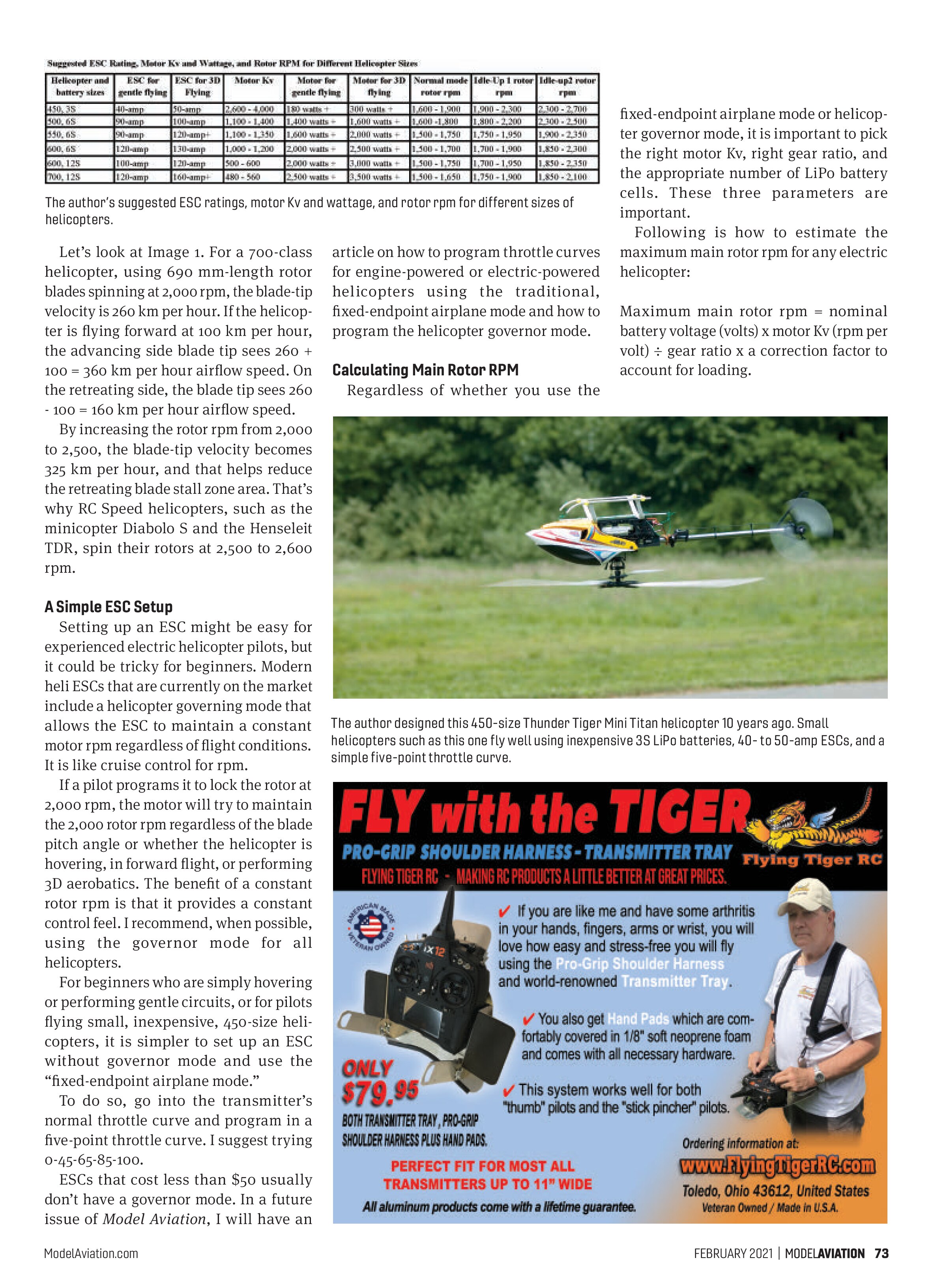
The author’s suggested ESC ratings, motor Kv and wattage, and rotor rpm for different sizes of helicopters.
Let’s look at Image 1. For a 700-class helicopter, using 690 mm-length rotor blades spinning at 2,000 rpm, the blade-tip velocity is 260 km per hour. If the helicopter is flying forward at 100 km per hour, the advancing side blade tip sees 260 + 100 = 360 km per hour airflow speed. On the retreating side, the blade tip sees 260 - 100 = 160 km per hour airflow speed.
By increasing the rotor rpm from 2,000 to 2,500, the blade-tip velocity becomes 325 km per hour, and that helps reduce the retreating blade stall zone area. That’s why RC Speed helicopters, such as the minicopter Diabolo S and the Henseleit TDR, spin their rotors at 2,500 to 2,600 rpm.
A Simple ESC Setup
Setting up an ESC might be easy for experienced electric helicopter pilots, but it could be tricky for beginners. Modern heli ESCs that are currently on the market include a helicopter governing mode that allows the ESC to maintain a constant motor rpm regardless of flight conditions. It is like cruise control for rpm.
If a pilot programs it to lock the rotor at 2,000 rpm, the motor will try to maintain the 2,000 rotor rpm regardless of the blade pitch angle or whether the helicopter is hovering, in forward flight, or performing 3D aerobatics. The benefit of a constant rotor rpm is that it provides a constant control feel. I recommend, when possible, using the governor mode for all helicopters.
For beginners who are simply hovering or performing gentle circuits, or for pilots flying small, inexpensive, 450-size helicopters, it is simpler to set up an ESC without governor mode and use the “fixed-endpoint airplane mode.”
To do so, go into the transmitter’s normal throttle curve and program in a five-point throttle curve. I suggest trying 0-45-65-85-100.
ESCs that cost less than $50 usually don’t have a governor mode. In a future issue of Model Aviation, I will have an article on how to program throttle curves for engine-powered or electric-powered helicopters using the traditional, fixed-endpoint airplane mode and how to program the helicopter governor mode.
Calculating Main Rotor RPM
Regardless of whether you use the fixed-endpoint airplane mode or helicopter governor mode, it is important to pick the right motor Kv, right gear ratio, and the appropriate number of LiPo battery cells. These three parameters are important.
Following is how to estimate the maximum main rotor rpm for any electric helicopter:
Maximum main rotor rpm = nominal battery voltage (volts) x motor Kv (rpm per volt) ÷ gear ratio x a correction factor to account for loading.

The manufacturer’s Kv rating for a brushless motor assumes that the motor is spinning freely without loading. In reality, the motor rpm depends on how much external load is applied. When a pilot applies collective pitch, the aerodynamic loading will slow down the motor. The motor also has to power the tail rotor and overcome drag in the complete drive system. These loadings could reduce the motor’s free-spinning rpm by 10% to 25%.
Let’s assume that we do not apply an unreasonable amount of collective pitch to bog down the motor and use a correction factor of 0.85, meaning a 15% reduction of free motor rpm because of loading. In this example, a helicopter has a motor-to-main-rotor-gear ratio of 9.6 to 1 (with a 115-tooth main gear and a 12-tooth motor pinion). What motor Kv and battery cell count should you use to obtain a main rotor rpm of approximately 2,100 at 100% full throttle? For simplicity, always assume four volts per LiPo cell.
Using an electric motor with a Kv of 500 and 12 LiPo cells yields 4 volts x 12 cells x 500 ÷ by 9.6 x 0.85 = 2,125 rpm. After playing around with many electric motors, I have found that a correction factor of 0.85 to 0.89 works best.
I asked a friend to use an optical tachometer to measure my rotor rpm when I was hovering in the Idle-Up 2 mode using the fixed-endpoint airplane mode with a flat throttle curve of 100-100-100-100-100. He measured 2,225 rpm. This is because, during a hover, the blade-pitch angle was at approximately 4°. During a climb and during aerobatics, the extra aerodynamic loading will likely reduce the rotor rpm to 2,100.
This is why, if you use the governor mode, you will set the maximum rpm to only 2,000 to 2,100 so that there is some headroom to allow the ESC and motor to work together to maintain a constant rpm.
Confirming Optimal Motor Running
Simply choosing the right Kv for a motor is not enough. It is important to ensure that the motor has adequate torque. For 700-class helicopters, a 3,000 to 4,000-watt motor is more than enough for sport flying. Do not install a 6,000-watt motor in a helicopter just because it is available. Too much horsepower could overstress the mechanics and become dangerous: 746 watts = 1 hp.
If you have chosen the proper size of electric motor, when full collective pitch is applied (+12° to +14°), the motor should not bog down. If your helicopter climbs rapidly straight up and out of sight with no sign of reduction in the rotor rpm, that means that the battery voltage, helicopter gear ratio, motor Kv, and collective-pitch travel range are well matched. If the motor bogs down, the motor could be inadequate or the gear ratio is wrong. When performing this climb test, you need to climb at full power for at least 200 feet to get a good reading.
Another sign of using a motor that is too small is that it is extremely hot after a flight. You should be able to touch the motor and leave your finger there for 3 seconds without being burned. Do the same finger test for the ESC. If the ESC is too hot, a larger one is required, or add a cooling fan, heat sink, or ventilation. It is always safer to use an ESC with a higher current rating. I have provided my suggested hardware ratings and rotor rpms in the table.
Assuming the motor selected has enough torque or power (watts), there are three options to achieve higher rotor rpm:
- Reduce the gear ratio
- Switch to a higher Kv motor
- Increase the number of LiPo battery cells
A well set-up helicopter always flies better. It pays to spend time on the workbench to carefully build and fine-tune the model.

SOURCES:
International Radio Controlled Helicopter Association (IRCHA)
www.ircha.org