AN ENJOYABLE AEROBATIC MODEL AT A REASONABLE COST
Phoenix Model Edge 540 .46-.55 GP EP ARF
By Joe Hass | joehass@gmail.com
Photos by John Hakala

THE PHOENIX MODEL EDGE 540 is an attractive, semiscale, aerobatic aircraft that includes all of the hardware to be powered by either glow (O.S. 1.20 two-stroke engine recommended), gas (DLE-20 20cc), or electric (RimFire 120) power. In addition to the power system hardware, there is an extensive and well-organized group of horns, hinges, ball links, etc.
Pull-pull hardware for the rudder is included and it is recommended that if you choose electric power to obtain the proper center of gravity (CG). The 50-page manual is pictorial with little text. The Edge is not a good first aircraft or first build.
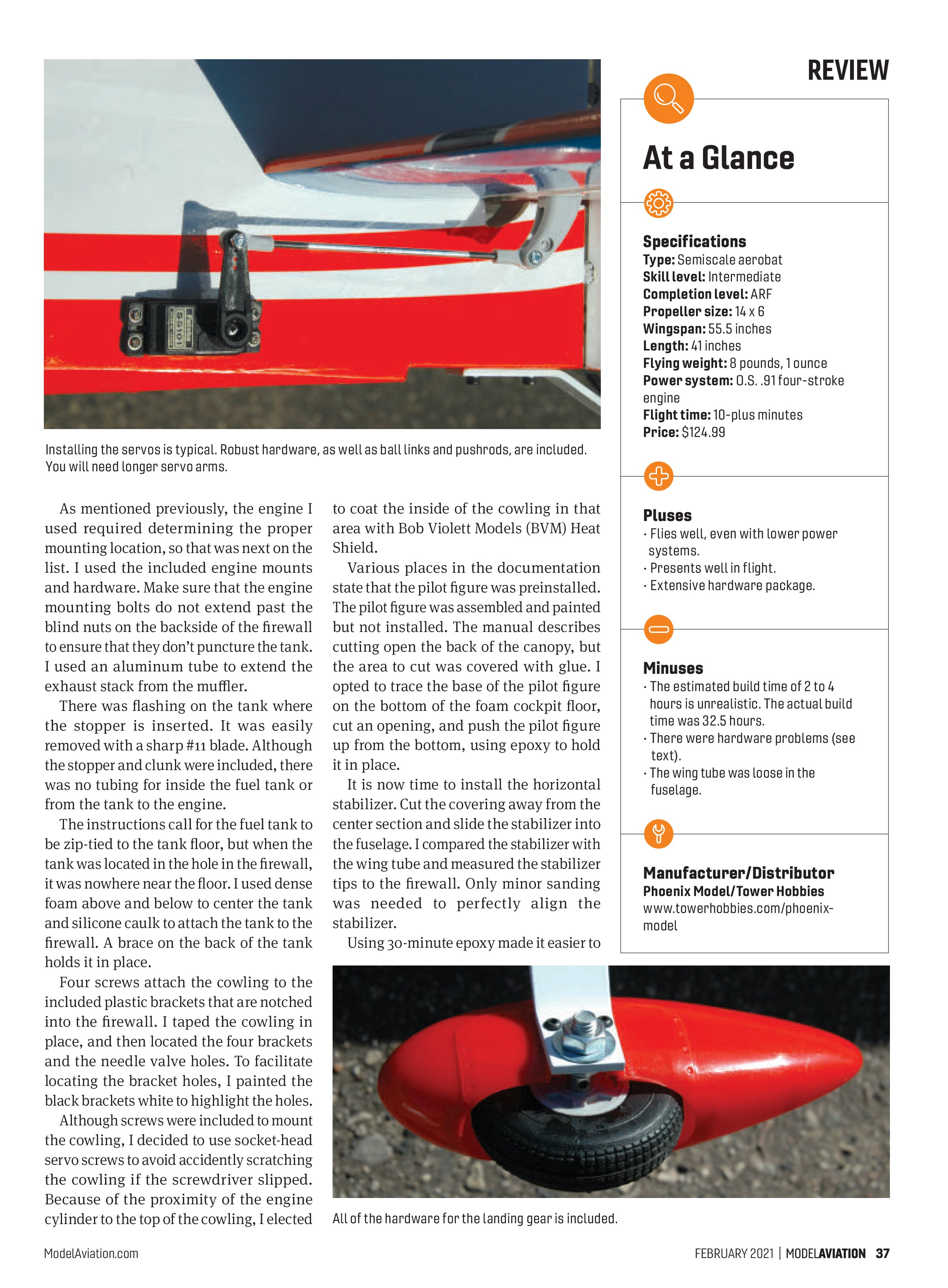
Although it is not in the recommended engine range, I chose to use a trusty O.S. .91 four-stroke engine. This engine required a different mounting location, but it resulted in a fully cowled engine. Although it is at the low end of the recommended engines, the .91, with an APC 14 x 6 propeller, provided great flight performance, including plenty of vertical for Hammerhead and wingover maneuvers.
The airframe is well packaged. Only two small areas of the covering needed minor tightening. An experienced builder will customize the build sequence as I did.
The instructions call for adding reinforcements and painting the engine box. It was a pleasant
surprise to see a laser-cut latch on the root ribs to hold the servo lead in place.
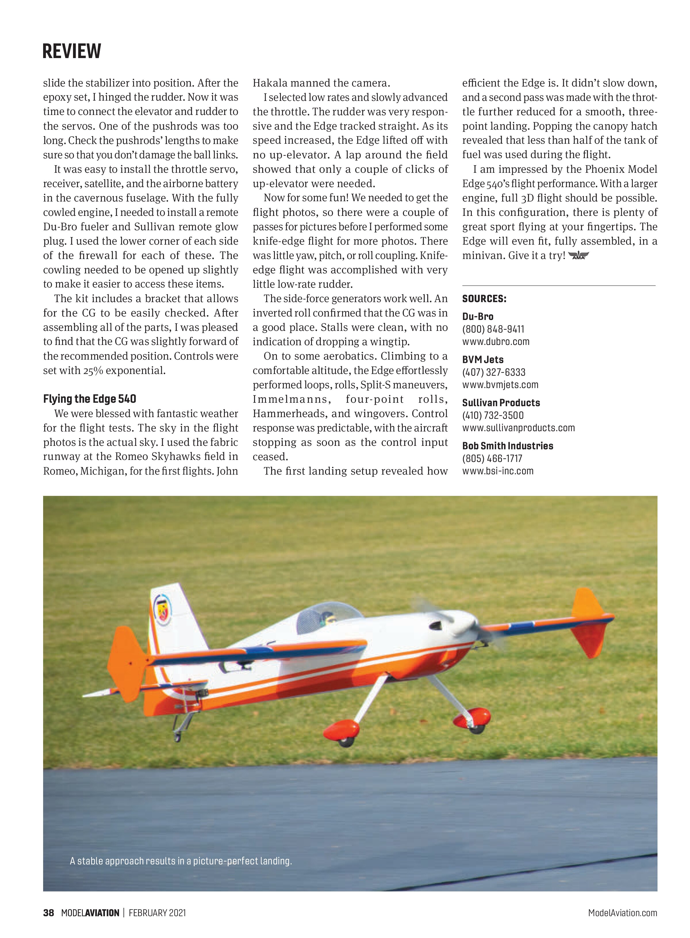
All of the control horns are robust and include alignment keys that fit in the precut slots in the control surfaces. Very nice. The aileron pushrods had damaged threads. Make sure you that clean them up before inserting the ball links, otherwise, the plastic will be damaged. You will need long servo arms, such as those available from Du-Bro, to match your servos.
When test-mounting the wing to the fuselage, I found the wing tube to be a great fit in each wing half but quite loose in the fuselage. Wrapping layers of clear shipping tape around the center section of

When test-mounting the wing to the fuselage, I found the wing tube to be a great fit in each wing half but quite loose in the fuselage. Wrapping layers of clear shipping tape around the center section of the wing tube solved that problem.

The wing hold-down bolts would not thread into the wing. A tap in each of the four locations solved that problem. The same problem was encountered with the side-force generators. Again, a tap cleaned up the threads.
The first work on the fuselage was to attach the elevator and rudder servos and route the servo leads with extensions through the fuselage. There are conveniently located holes in each fuselage former to hold the servo leads.
I assembled the wheel pants and mounted the wheels and the wheel pants before attaching the gear to the fuselage. The wheel pants need to be cut to match the nut on the axle and drilled to match the holes in the landing gear. The axles need to be cut slightly to fit in the wheel pants. The wheel spacers were not large enough to center the wheel in the wheel pants, so I replaced them with Du-Bro wheel collars.
Attaching the landing gear to the fuselage is accomplished with four bolts. This allows you to easily add a bit of tow-in to aid in ground tracking. The matching surface on the fuselage is hard so that the gear will move, even if the bolts are tight. I solved that problem with self-adhesive sandpaper applied to the backside of the landing gear and the fender washers under the bolts.
The tail wheel is completely assembled. Two bolts hold the assembly to the fuselage with already installed blind nuts. I added the tiller on the bottom of the rudder. Springs are included to connect the rudder to the tail wheel.

As mentioned previously, the engine I used required determining the proper mounting location, so that was next on the list. I used the included engine mounts and hardware. Make sure that the engine mounting bolts do not extend past the blind nuts on the backside of the firewall to ensure that they don’t puncture the tank. I used an aluminum tube to extend the exhaust stack from the muffler.
There was flashing on the tank where the stopper is inserted. It was easily removed with a sharp #11 blade. Although the stopper and clunk were included, there was no tubing for inside the fuel tank or from the tank to the engine.
The instructions call for the fuel tank to be zip-tied to the tank floor, but when the tank was located in the hole in the firewall, it was nowhere near the floor. I used dense foam above and below to center the tank and silicone caulk to attach the tank to the firewall. A brace on the back of the tank holds it in place.
Four screws attach the cowling to the included plastic brackets that are notched into the firewall. I taped the cowling in place, and then located the four brackets and the needle valve holes. To facilitate locating the bracket holes, I painted the black brackets white to highlight the holes.
Although screws were included to mount the cowling, I decided to use socket-head servo screws to avoid accidentally scratching the cowling if the screwdriver slipped. Because of the proximity of the engine cylinder to the top of the cowling, I elected to coat the inside of the cowling in that area with Bob Violett Models (BVM) Heat Shield.
Various places in the documentation state that the pilot figure was preinstalled. The pilot figure was assembled and painted but not installed. The manual describes cutting open the back of the canopy, but the area to cut was covered with glue. I opted to trace the base of the pilot figure on the bottom of the foam cockpit floor, cut an opening, and push the pilot figure up from the bottom, using epoxy to hold it in place.
It is now time to install the horizontal stabilizer. Cut the covering away from the center section and slide the stabilizer into the fuselage. I compared the stabilizer with the wing tube and measured the stabilizer tips to the firewall. Only minor sanding was needed to perfectly align the stabilizer.
Using 30-minute epoxy made it easier
At a Glance
Specifications
Type: Semiscale aerobat
Skill level: Intermediate
Completion level: ARF
Propeller size: 14 x 6
Wingspan: 55.5 inches
Length: 41 inches
Flying weight: 8 pounds, 1 ounce
Power system: O.S. .91 four-stroke engine
Flight time: 10-plus minutes
Price: $124.99
Pluses
- Flies well, even with lower power systems.
- Presents well in flight.
- Extensive hardware package.
Minuses
- The estimated build time of 2 to 4 hours is unrealistic. The actual build time was 32.5 hours.
- There were hardware problems (see text).
- The wing tube was loose in the fuselage.
Manufacturer/Distributor
Phoenix Model/Tower Hobbies
www.towerhobbies.com/phoenix-model

slide the stabilizer into position. After the epoxy set, I hinged the rudder. Now it was time to connect the elevator and rudder to the servos. One of the pushrods was too long. Check the pushrods’ lengths to make sure so that you don’t damage the ball links.
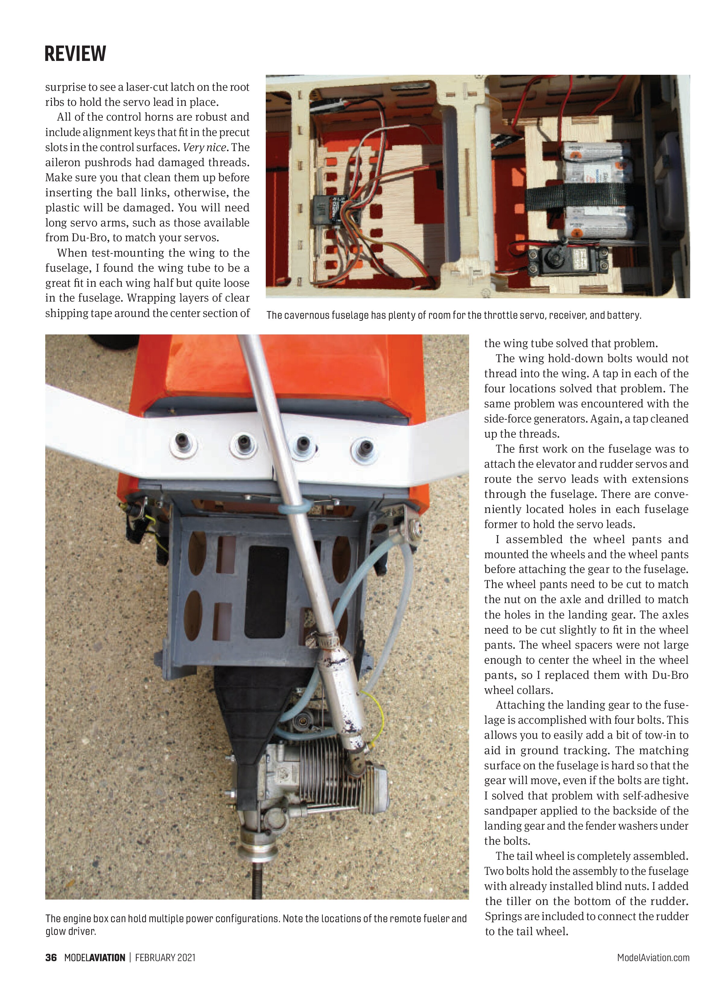
It was easy to install the throttle servo, receiver, satellite, and the airborne battery in the cavernous fuselage. With the fully cowled engine, I needed to install a remote Du-Bro fueler and Sullivan remote glow plug. I used the lower corner of each side of the firewall for each of these. The cowling needed to be opened up slightly to make it easier to access these items.
The kit includes a bracket that allows for the CG to be easily checked. After assembling all of the parts, I was pleased to find that the CG was slightly forward of the recommended position. Controls were set with 25% exponential.
Flying the Edge 540
We were blessed with fantastic weather for the flight tests. The sky in the flight photos is the actual sky. I used the fabric runway at the Romeo Skyhawks field in Romeo, Michigan, for the first flights. John Hakala manned the camera.
I selected low rates and slowly advanced the throttle. The rudder was very responsive and the Edge tracked straight. As its speed increased, the Edge lifted off with no up-elevator. A lap around the field showed that only a couple of clicks of up-elevator were needed.
Now for some fun! We needed to get the flight photos, so there were a couple of passes for pictures before I performed some knife-edge flight for more photos. There was little yaw, pitch, or roll coupling. Knife-edge flight was accomplished with very little low-rate rudder.
The side-force generators work well. An inverted roll confirmed that the CG was in a good place. Stalls were clean, with no indication of dropping a wingtip.
On to some aerobatics. Climbing to a comfortable altitude, the Edge effortlessly performed loops, rolls, Split-S maneuvers, Immelmanns, four-point rolls, Hammerheads, and wingovers. Control response was predictable, with the aircraft stopping as soon as the control input ceased.
The first landing setup revealed how efficient the Edge is. It didn’t slow down, and a second pass was made with the throttle further reduced for a smooth, three-point landing. Popping the canopy hatch revealed that less than half of the tank of fuel was used during the flight.
I am impressed by the Phoenix Model Edge 540’s flight performance. With a larger engine, full 3D flight should be possible. In this configuration, there is plenty of great sport flying at your fingertips. The Edge will even fit, fully assembled, in a minivan. Give it a try!
SOURCES:
Du-Bro
(800) 848-9411
www.dubro.com
BVM Jets
(407) 327-6333
www.bvmjets.com
Sullivan Products
(410) 732-3500
www.sullivanproducts.com
Bob Smith Industries
(805) 466-1717
www.bsi-inc.com