RC SOARING

THE PHYSICS
OF AN F3J
LAUNCH
By Gordon Buckland | gordon@gatorf3h.com
DENNIS L. HARVEY has written a guest column for this month.
I was an avid RC sailplane pilot during the 1970s, but because of my engineering career, I took a long break. I returned to the sport in 2017 when I moved from the Midwest to central Florida. I was wowed by the innovations throughout those 35 years, from the competitiveness of full-house controls, to the miniaturization of electronics, to the extensive use of carbon fiber.
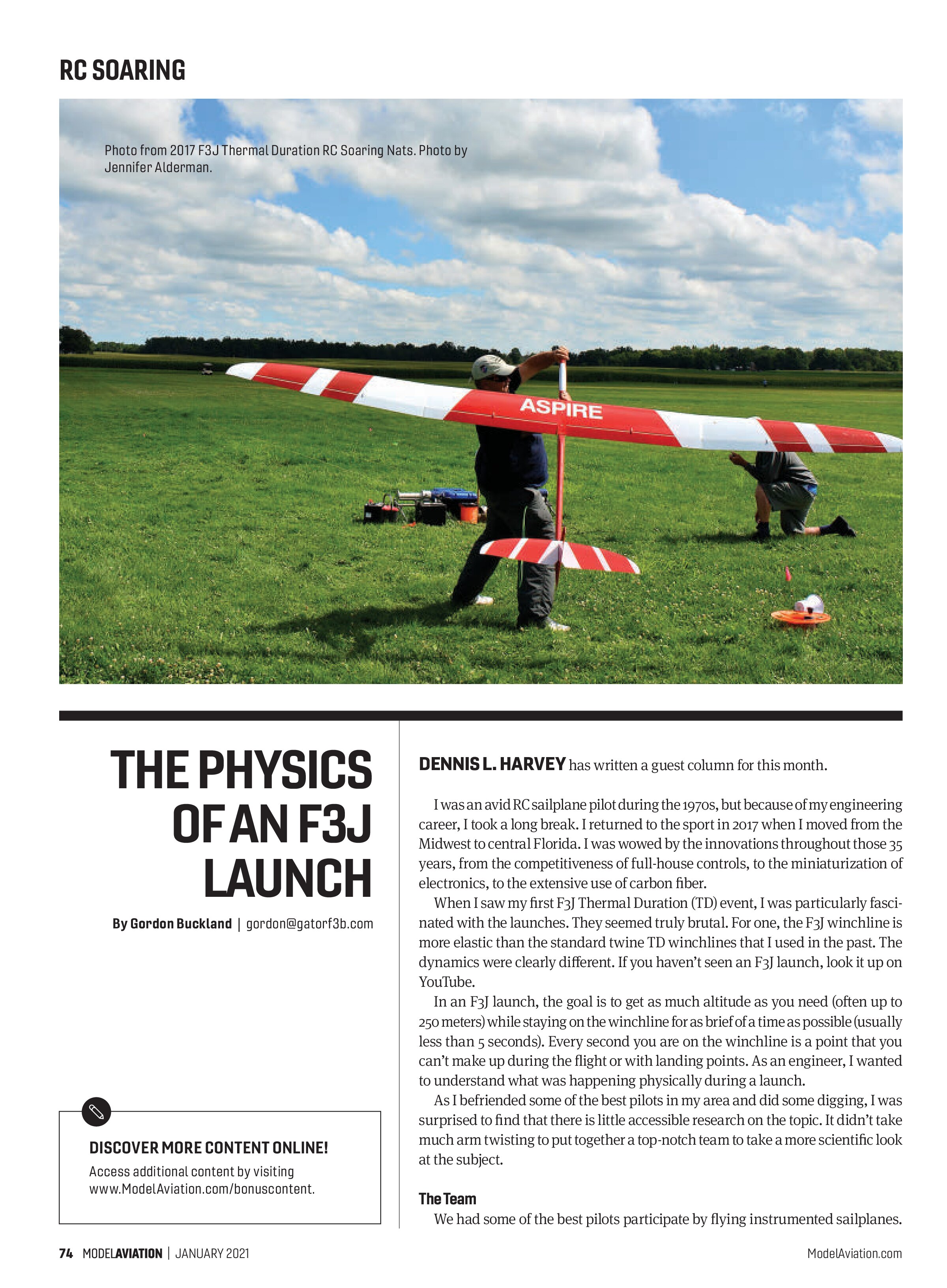
When I saw my first F3J Thermal Duration (TD) event, I was particularly fascinated with the launches. They seemed truly brutal. For one, the F3J winchline is more elastic than the standard twine TD winchlines that I used in the past. The dynamics were clearly different. If you haven’t seen an F3J launch, look it up on YouTube.
In an F3J launch, the goal is to get as much altitude as you need (often up to 250 meters) while staying on the winchline for as brief of a time as possible (usually less than 5 seconds). Every second you are on the winchline is a point that you can’t make up during the flight or with landing points. As an engineer, I wanted to understand what was happening physically during a launch.
As I befriended some of the best pilots in my area and did some digging, I was surprised to find that there is little accessible research on the topic. It didn’t take much arm twisting to put together a top-notch team to take a more scientific look at the subject.
The Team
We had some of the best pilots participate by flying instrumented sailplanes.
Three team members are part of Team SoaringUSA, representing the US on the international F3J circuit. Jody Miller took second place at the last international competition in 2018. Jeff Duval is currently the number-one US pilot for the next competition. Gordon Buckland has been on Team USA F3J numerous times and is a quintessential organizer for the sport. Ed Dumas, who drove down from Tennessee for our January 2020 flight weekend, provided invaluable expertise on flying and instrumentation.
Although I didn’t have the flying credentials of the others, I was quite at home with experimental design because it was often part of my career.
The Approach
The core of the experimental design was to measure the sailplane’s energy state as it progressed through the launch. The total energy of the sailplane is the sum of its potential energy (proportional to altitude) and its kinetic energy (proportional to speed squared). Additionally, we wanted to record the launch from onboard to determine the wing loading (based on wing flex), and the angle of the winchline and the horizon. Wherever possible, we tried to confirm our findings through a secondary measurement or calculation.
A Representative Launch Example
To keep this article simple, I will show only one of 26 launches. The launch is representative of a high-performance F3J launch. Jody was the pilot, flying a carbon-fiber 3.8-meter wingspan Xplorer3 F3J model (a common sailplane at F3J events). The flight day temperature was 80° F, ground level was 60 feet above sea level, and the wind was less than 4 mph.
Jody’s launch attained an altitude of 251 meters, with a time on the winchline of 4.8 seconds. Flaps were initially set at 15 mm down (12°) until the “Bucket” phase, when they were set for speed at 3 mm. We used a standard competition winch with a 1.32 mm diameter winchline.
The Instrumentation
The key to getting a potential energy determination was to have an accurate altimeter. Onboard the sailplane, Ed offered the use of a Hexpert altimeter that could easily record every 1/10 second. For kinetic energy, we used a FrSky airspeed sensor. Unfortunately, its data sampling rate was no better than 0.2 seconds. As a result, when graphed every 1/10 second, the data had a “sawtooth” look to it compared with the Hexpert data. Still, the data was accurate enough to give us insight and could be corroborated by other collected information.

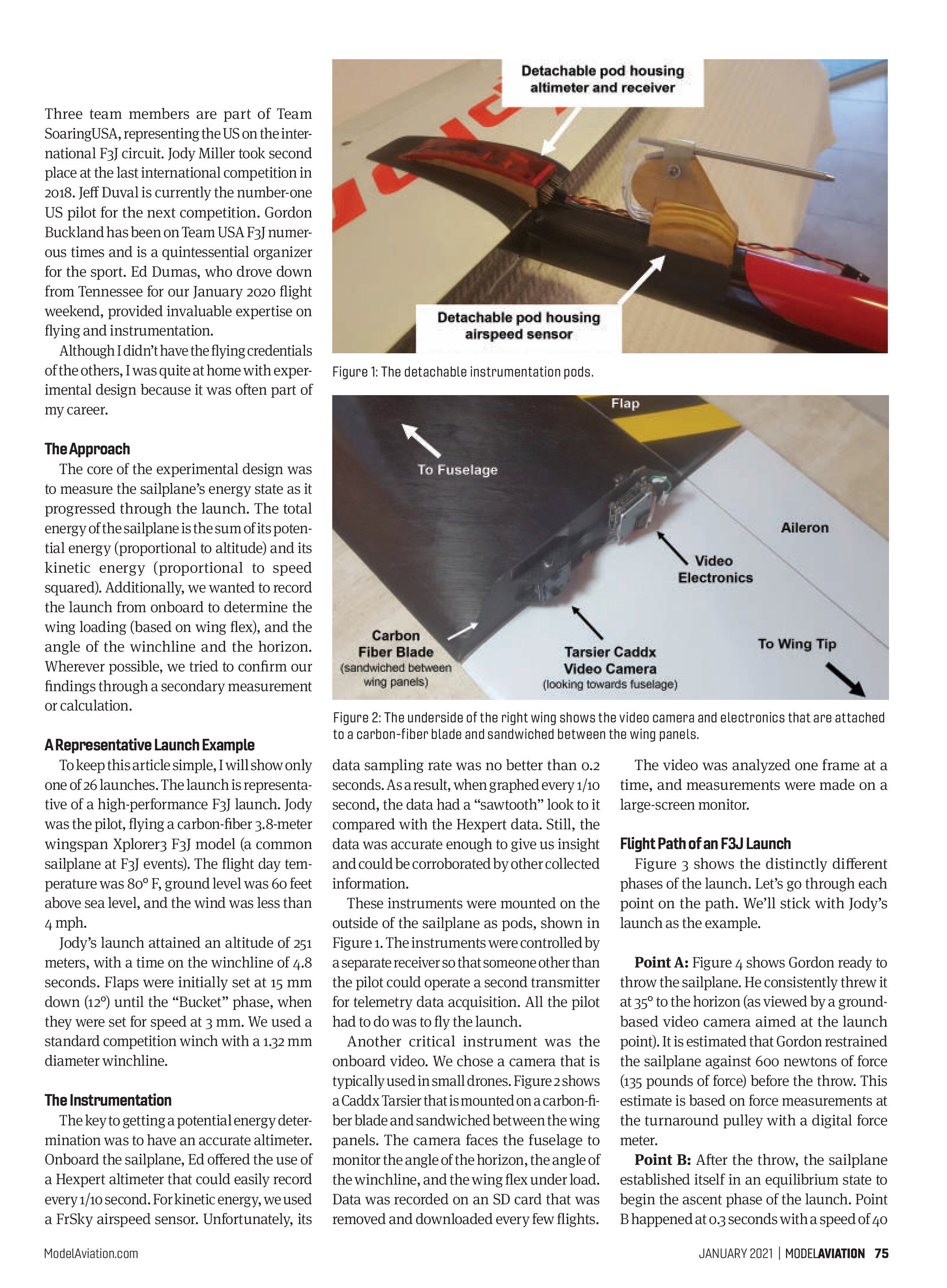
These instruments were mounted on the outside of the sailplane as pods, shown in Figure 1. The instruments were controlled by a separate receiver so that someone other than the pilot could operate a second transmitter for telemetry data acquisition. All the pilot had to do was to fly the launch.
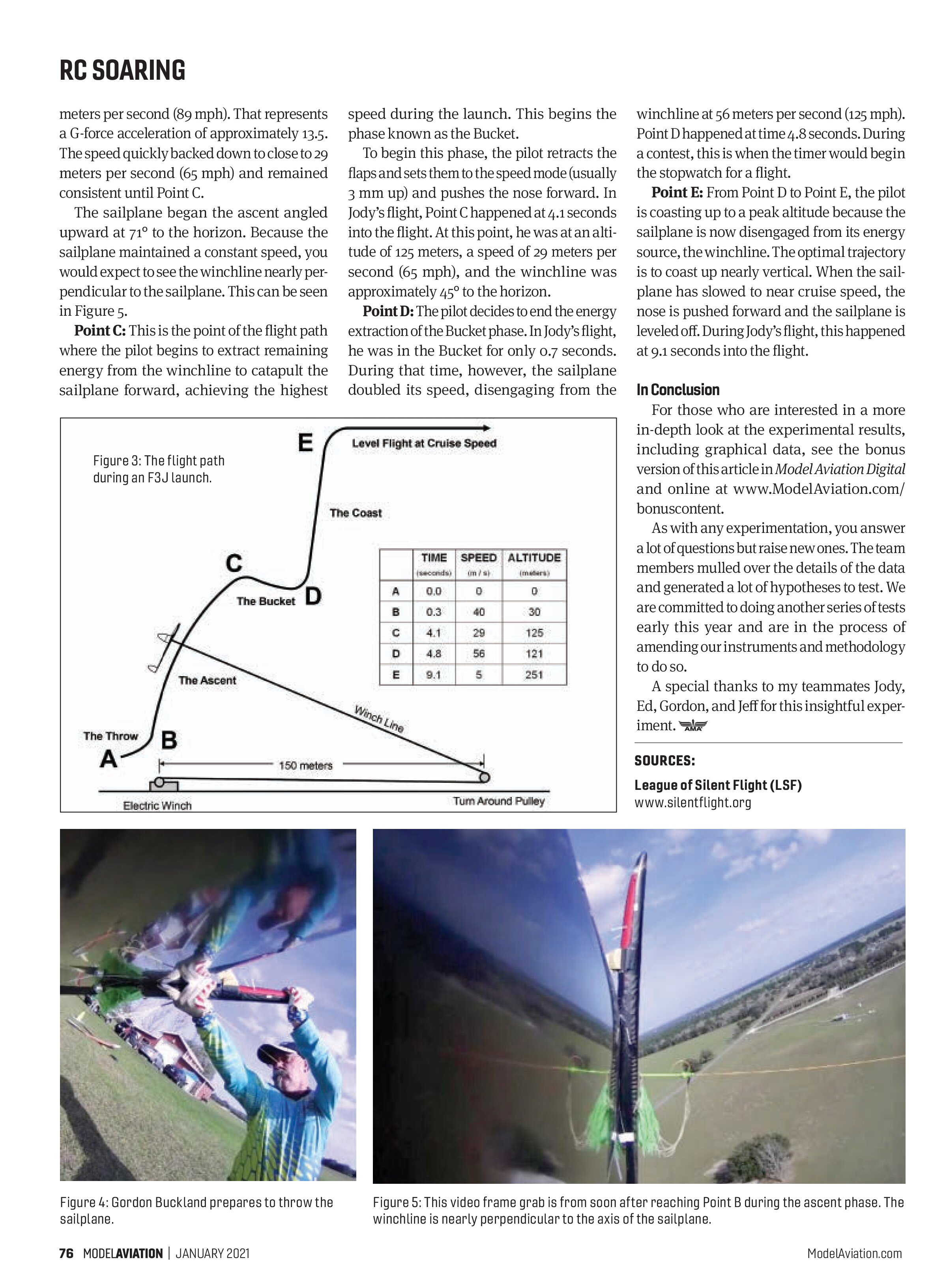
Another critical instrument was the onboard video. We chose a camera that is typically used in small drones. Figure 2 shows a Caddx Tarsier that is mounted on a carbon-fiber blade and sandwiched between the wing panels. The camera faces the fuselage to monitor the angle of the horizon, the angle of the winchline, and the wing flex under load. Data was recorded on an SD card that was removed and downloaded every few flights.

The video was analyzed one frame at a time, and measurements were made on a large-screen monitor.
Flight Path of an F3J Launch
Figure 3 shows the distinctly different phases of the launch. Let’s go through each point on the path. We’ll stick with Jody’s launch as the example.
Point A: Figure 4 shows Gordon ready to throw the sailplane. He consistently threw it at 35° to the horizon (as viewed by a ground-based video camera aimed at the launch point). It is estimated that Gordon restrained the sailplane against 600 newtons of force (135 pounds of force) before the throw. This estimate is based on force measurements at the turnaround pulley with a digital force meter.
Point B: After the throw, the sailplane established itself in an equilibrium state to begin the ascent phase of the launch. Point B happened at 0.3 seconds with a speed of 40
meters per second (89 mph). That represents a G-force acceleration of approximately 13.5. The speed quickly backed down to close to 29 meters per second (65 mph) and remained consistent until Point C.
The sailplane began the ascent angled upward at 71° to the horizon. Because the sailplane maintained a constant speed, you would expect to see the winchline nearly perpendicular to the sailplane. This can be seen in Figure 5.
Point C: This is the point of the flight path where the pilot begins to extract remaining energy from the winchline to catapult the sailplane forward, achieving the highest

speed during the launch. This begins the phase known as the Bucket.
To begin this phase, the pilot retracts the flaps and sets them to the speed mode (usually 3 mm up) and pushes the nose forward. In Jody’s flight, Point C happened at 4.1 seconds into the flight. At this point, he was at an altitude of 125 meters, a speed of 29 meters per second (65 mph), and the winchline was approximately 45° to the horizon.
Point D: The pilot decides to end the energy extraction of the Bucket phase. In Jody’s flight, he was in the Bucket for only 0.7 seconds. During that time, however, the sailplane doubled its speed, disengaging from the winchline at 56 meters per second (125 mph). Point D happened at time 4.8 seconds. During a contest, this is when the timer would begin the stopwatch for a flight.
Point E: From Point D to Point E, the pilot is coasting up to a peak altitude because the sailplane is now disengaged from its energy source, the winchline. The optimal trajectory is to coast up nearly vertical. When the sailplane has slowed to near cruise speed, the nose is pushed forward and the sailplane is leveled off. During Jody’s flight, this happened at 9.1 seconds into the flight.
In Conclusion
For those who are interested in a more in-depth look at the experimental results, including graphical data, see the bonus version of this article in Model Aviation Digital and online at www.ModelAviation.com/bonuscontent.
As with any experimentation, you answer a lot of questions but raise new ones. The team members mulled over the details of the data and generated a lot of hypotheses to test. We are committed to doing another series of tests early this year and are in the process of amending our instruments and methodology to do so.
A special thanks to my teammates Jody, Ed, Gordon, and Jeff for this insightful experiment.


SOURCES:
League of Silent Flight (LSF)
www.silentflight.org