Radii within a given maneuver
by John Glezellis
jglezellis@gmail.com
Successful International Miniature Aerobatic Club (IMAC) competitors value the importance of proper building, programming, and trimming techniques. These individuals also fully understand how to interpret and perform an Aresti sequence in accordance with judging criteria, which is of equal magnitude.
Throughout the years, I have seen many competent pilots who have had the flying abilities needed to win, but they struggle with knowing how to read Aresti diagrams and understanding the rules for judging. Some are simply unaware of all of the criteria that apply. It is my goal to increase that awareness to push them to become the best possible RC Aerobatics pilots.
This month’s column will revolve around radii within a given maneuver. Many modelers underestimate this subject because they assume that all radii must match. For some figures, however, radii do not have to be equal.
In addition to discussing radii with numerous examples, I will investigate a few setup practices that can help pilots decrease their workloads and promote consistent flight performance. Let’s get down to business!
Aresti and Radii Essentials
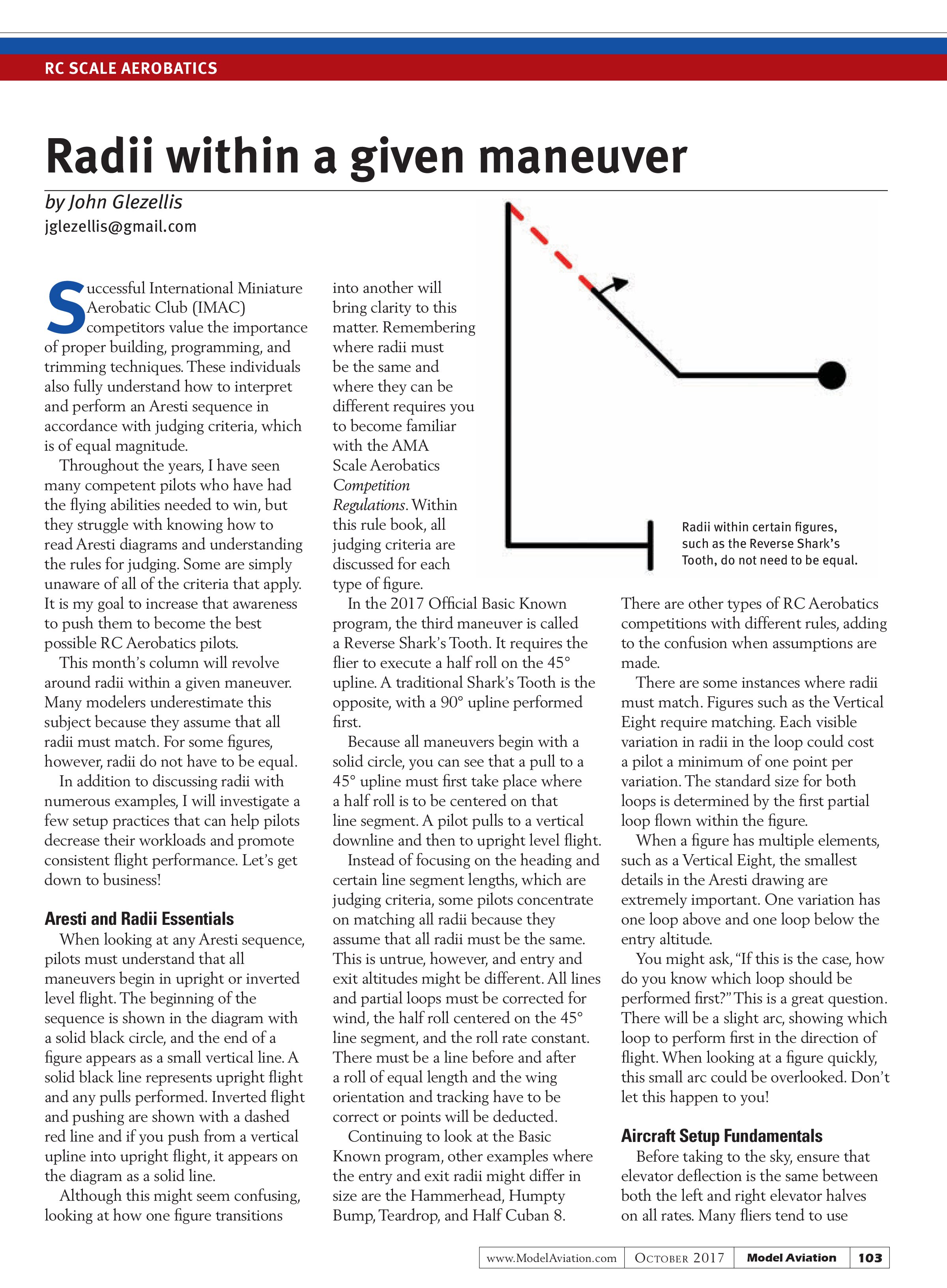
When looking at any Aresti sequence, pilots must understand that all maneuvers begin in upright or inverted level flight. The beginning of the sequence is shown in the diagram with a solid black circle, and the end of a figure appears as a small vertical line. A solid black line represents upright flight and any pulls performed. Inverted flight and pushing are shown with a dashed red line and if you push from a vertical upline into upright flight, it appears on the diagram as a solid line.
Although this might seem confusing, looking at how one figure transitions into another will bring clarity to this matter. Remembering where radii must be the same and where they can be different requires you to become familiar with the AMA Scale Aerobatics Competition Regulations. Within this rule book, all judging criteria are discussed for each type of figure.
In the 2017 Official Basic Known program, the third maneuver is called a Reverse Shark’s Tooth. It requires the flier to execute a half roll on the 45° upline. A traditional Shark’s Tooth is the opposite, with a 90° upline performed first.
Because all maneuvers begin with a solid circle, you can see that a pull to a 45° upline must first take place where a half roll is to be centered on that line segment. A pilot pulls to a vertical downline and then to upright level flight.
Instead of focusing on the heading and certain line segment lengths, which are judging criteria, some pilots concentrate on matching all radii because they assume that all radii must be the same. This is untrue, however, and entry and exit altitudes might be different. All lines and partial loops must be corrected for wind, the half roll centered on the 45° line segment, and the roll rate constant. There must be a line before and after a roll of equal length and the wing orientation and tracking have to be correct or points will be deducted.
Continuing to look at the Basic Known program, other examples where the entry and exit radii might differ in size are the Hammerhead, Humpty Bump, Teardrop, and Half Cuban 8.

There are other types of RC Aerobatics competitions with different rules, adding to the confusion when assumptions are made.
There are some instances where radii must match. Figures such as the Vertical Eight require matching. Each visible variation in radii in the loop could cost a pilot a minimum of one point per variation. The standard size for both loops is determined by the first partial loop flown within the figure.
When a figure has multiple elements, such as a Vertical Eight, the smallest details in the Aresti drawing are extremely important. One variation has one loop above and one loop below the entry altitude.
You might ask, “If this is the case, how do you know which loop should be performed first?” This is a great question. There will be a slight arc, showing which loop to perform first in the direction of flight. When looking at a figure quickly, this small arc could be overlooked. Don’t let this happen to you!
Aircraft Setup Fundamentals
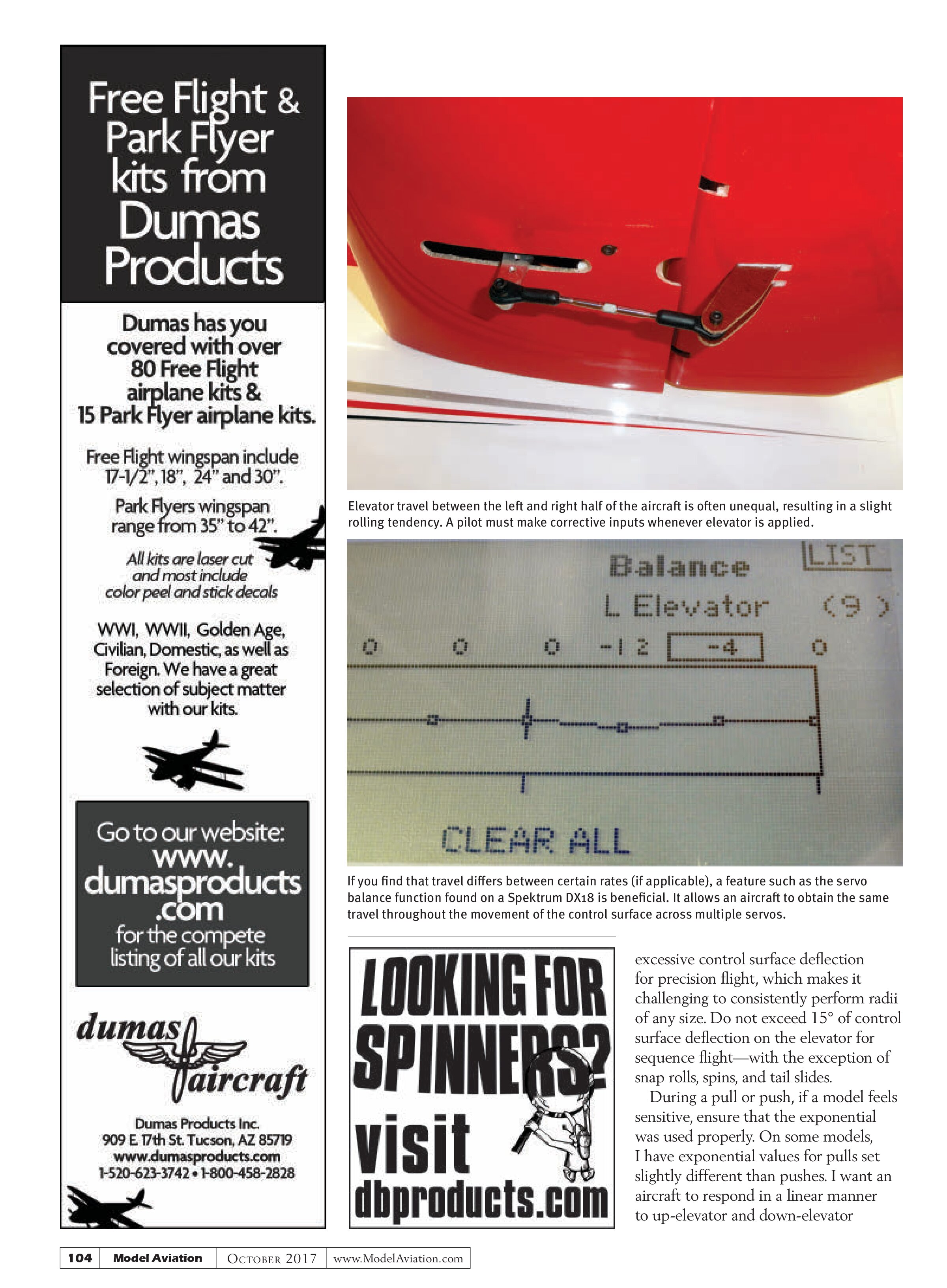
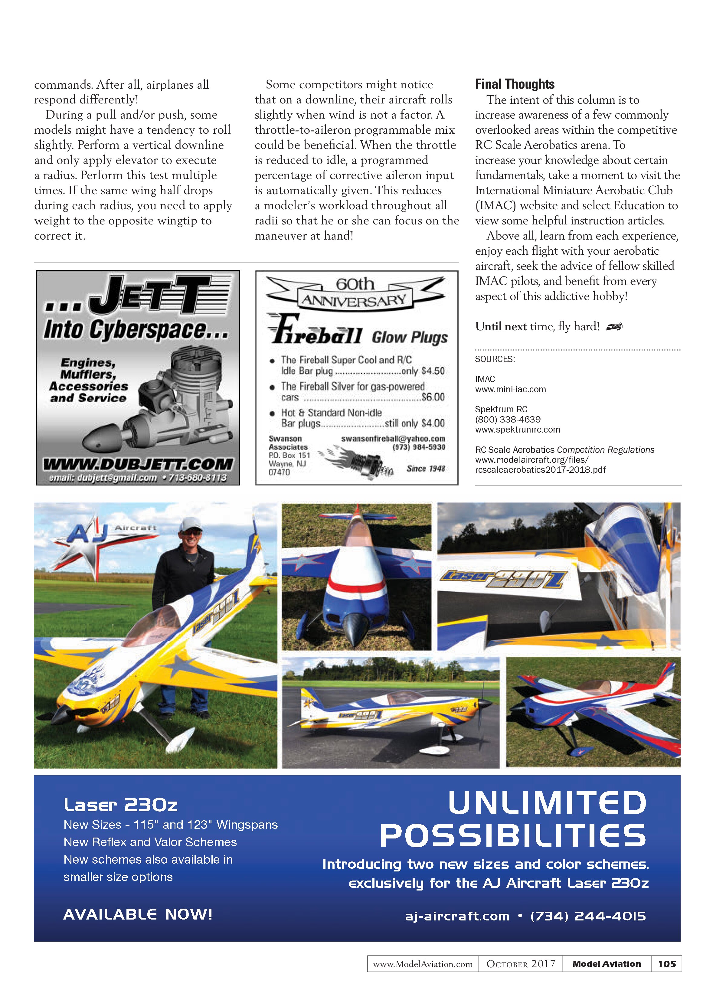
Before taking to the sky, ensure that elevator deflection is the same between both the left and right elevator halves on all rates. Many fliers tend to use


excessive control surface deflection for precision flight, which makes it challenging to consistently perform radii of any size. Do not exceed 15° of control surface deflection on the elevator for sequence flight—with the exception of snap rolls, spins, and tail slides.
During a pull or push, if a model feels sensitive, ensure that the exponential was used properly. On some models, I have exponential values for pulls set slightly different than pushes. I want an aircraft to respond in a linear manner to up-elevator and down-elevator commands. After all, airplanes all respond differently!
During a pull and/or push, some models might have a tendency to roll slightly. Perform a vertical downline and only apply elevator to execute a radius. Perform this test multiple times. If the same wing half drops during each radius, you need to apply weight to the opposite wingtip to correct it.
Some competitors might notice that on a downline, their aircraft rolls slightly when wind is not a factor. A throttle-to-aileron programmable mix could be beneficial. When the throttle is reduced to idle, a programmed percentage of corrective aileron input is automatically given. This reduces a modeler’s workload throughout all radii so that he or she can focus on the maneuver at hand!
Final Thoughts
The intent of this column is to increase awareness of a few commonly overlooked areas within the competitive RC Scale Aerobatics arena. To increase your knowledge about certain fundamentals, take a moment to visit the International Miniature Aerobatic Club (IMAC) website and select Education to view some helpful instruction articles.
Above all, learn from each experience, enjoy each flight with your aerobatic aircraft, seek the advice of fellow skilled IMAC pilots, and benefit from every aspect of this addictive hobby!
Until next time, fly hard!
SOURCES:
IMAC
www.mini-iac.com
Spektrum RC
(800) 338-4639
www.spektrumrc.com
RC Scale Aerobatics Competition Regulations
www.modelaircraft.org/files/
rcscaleaerobatics2017-2018.pdf