EC5s are EC5s … right?
Greg Gimlick
maelectrics@gimlick.com
I’m going to look at a couple of topics that I have received lately in emails. There is quite a hubbub about EC5 connectors, and I’m going to try to clear that up, along with some misconceptions about wire types.

An EC5 Is an EC5 Is an EC5 … Wrong!
An engineer friend of mind is fond of saying, “The nice thing about standards is there are so many.” It drives me crazy to accept that, but it’s the truth, and it certainly applies to our connectors.
Horizon Hobby brought us the EC5 connector as a big brother to the EC3, and it’s a darn good connector. As time went on, other EC5 connectors were brought to market by third-party manufacturers. They were less expensive than the original connectors, and shoppers being shoppers, they sold well. By the way, this also applies to the EC3.
So, what’s the problem? They aren’t all the same. They seem to mate to each other fine, but that’s where it ends.
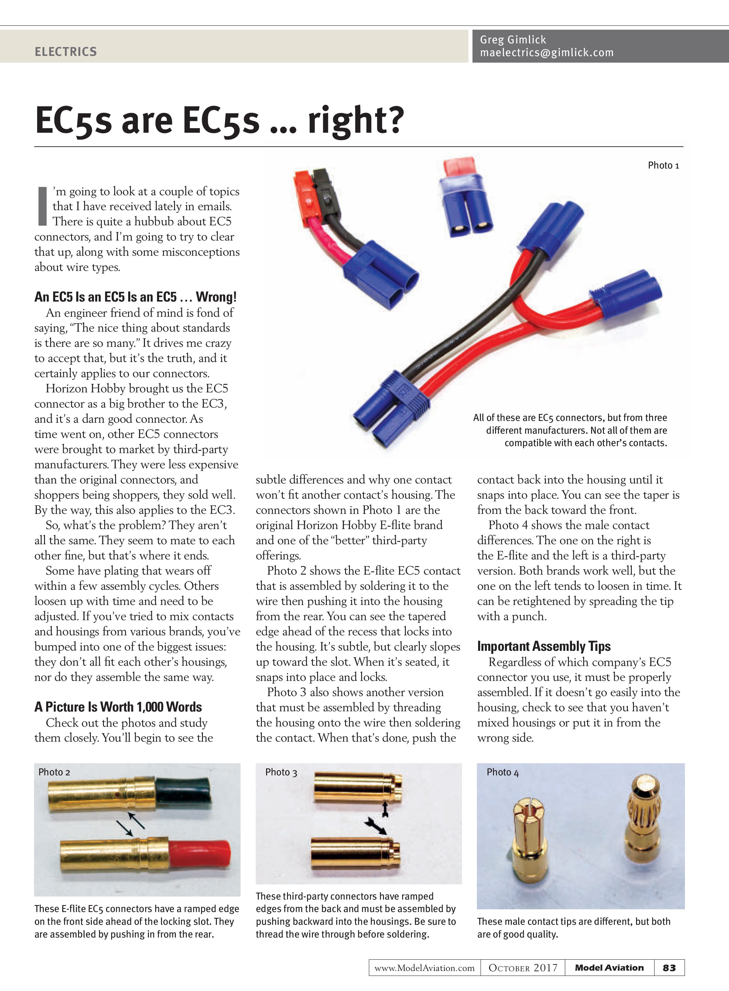
Some have plating that wears off within a few assembly cycles. Others loosen up with time and need to be adjusted. If you’ve tried to mix contacts and housings from various brands, you’ve bumped into one of the biggest issues; they don’t all fit each other’s housings, nor do they assemble the same way.
A Picture Is Worth 1,000 Words
Check out the photos and study them closely. You’ll begin to see the subtle differences and why one contact won’t fit another contact’s housing. The connectors shown in Photo 1 are the original Horizon Hobby E-flite brand and one of the “better” third-party offerings.
Photo 2 shows the E-flite EC5 contact that is assembled by soldering it to the wire then pushing it into the housing from the rear. You can see the tapered edge ahead of the recess that locks into the housing. It’s subtle, but clearly slopes up toward the slot. When it’s seated, it snaps into place and locks.
Photo 3 also shows another version that must be assembled by threading the housing onto the wire then soldering the contact. When that’s done, push the contact back into the housing until it snaps into place. You can see the taper is from the back toward the front.
Photo 4 shows the male contact differences. The one on the right is the E-flite and the left is a third-party version. Both brands work well, but the one on the left tends to loosen in time. It can be retightened by spreading the tip with a punch.
Important Assembly Tips
Regardless of which company’s EC5 connector you use, it must be properly assembled. If it doesn’t go easily into the housing, check to see that you haven’t mixed housings or put it in from the wrong side.


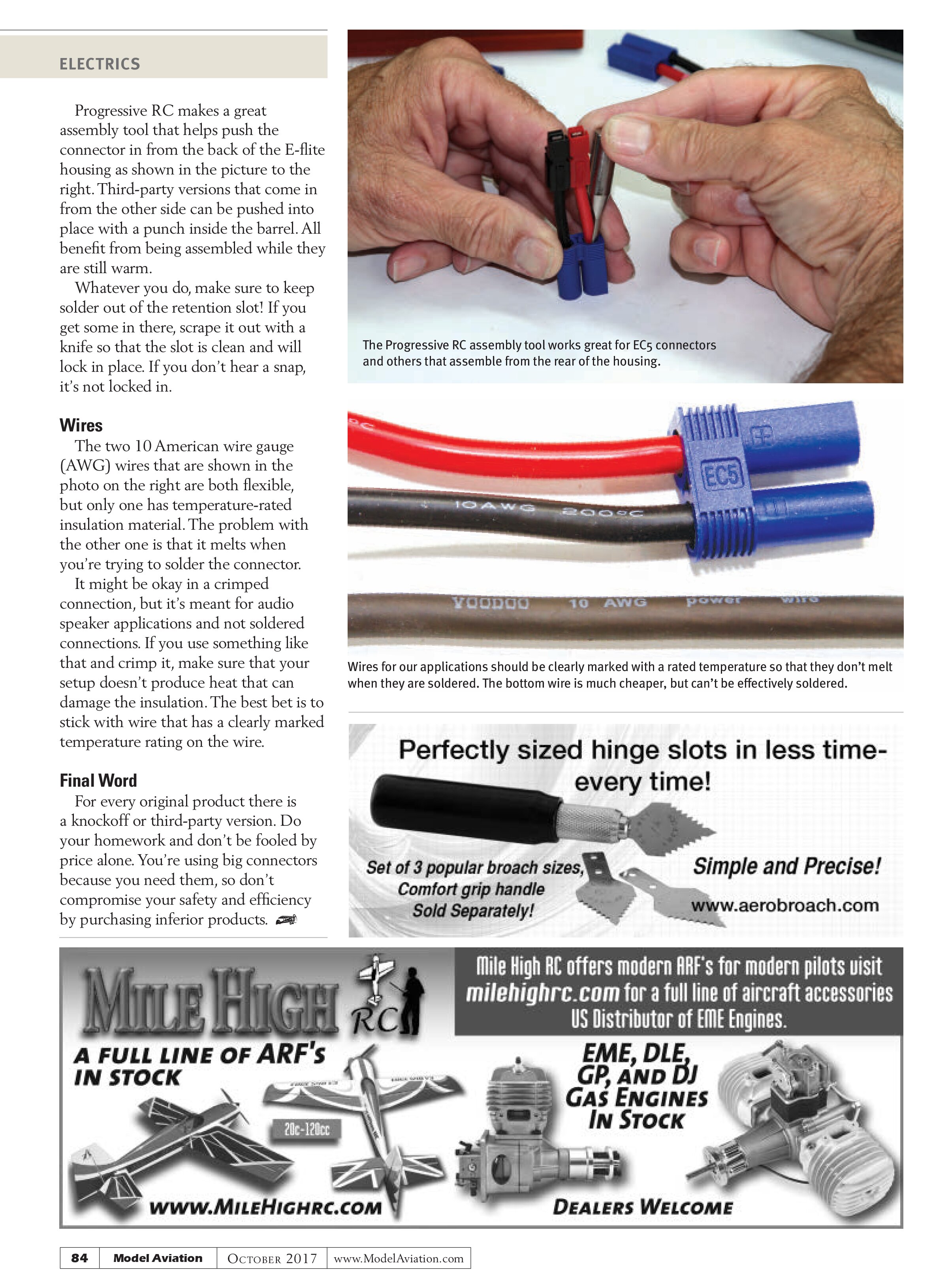
Progressive RC makes a great assembly tool that helps push the connector in from the back of the E-flite housing as shown in the picture to the right. Third-party versions that come in from the other side can be pushed into place with a punch inside the barrel. All benefit from being assembled while they are still warm.
Whatever you do, make sure to keep solder out of the retention slot! If you get some in there, scrape it out with a knife so that the slot is clean and will lock in place. If you don’t hear a snap, it’s not locked in.

Wires
The two 10 American wire gauge (AWG) wires that are shown in the photo on the right are both flexible, but only one has temperature-rated insulation material. The problem with the other one is that it melts when you’re trying to solder the connector.
It might be okay in a crimped connection, but it’s meant for audio speaker applications and not soldered connections. If you use something like that and crimp it, make sure that your setup doesn’t produce heat that can damage the insulation. The best bet is to stick with wire that has a clearly marked temperature rating on the wire.

Final Word
For every original product there is a knockoff or third-party version. Do your homework and don’t be fooled by price alone. You’re using big connectors because you need them, so don’t compromise your safety and efficiency by purchasing inferior products.