Determining the CG and thrust angles
by John Glezellis
jglezellis@gmail.com
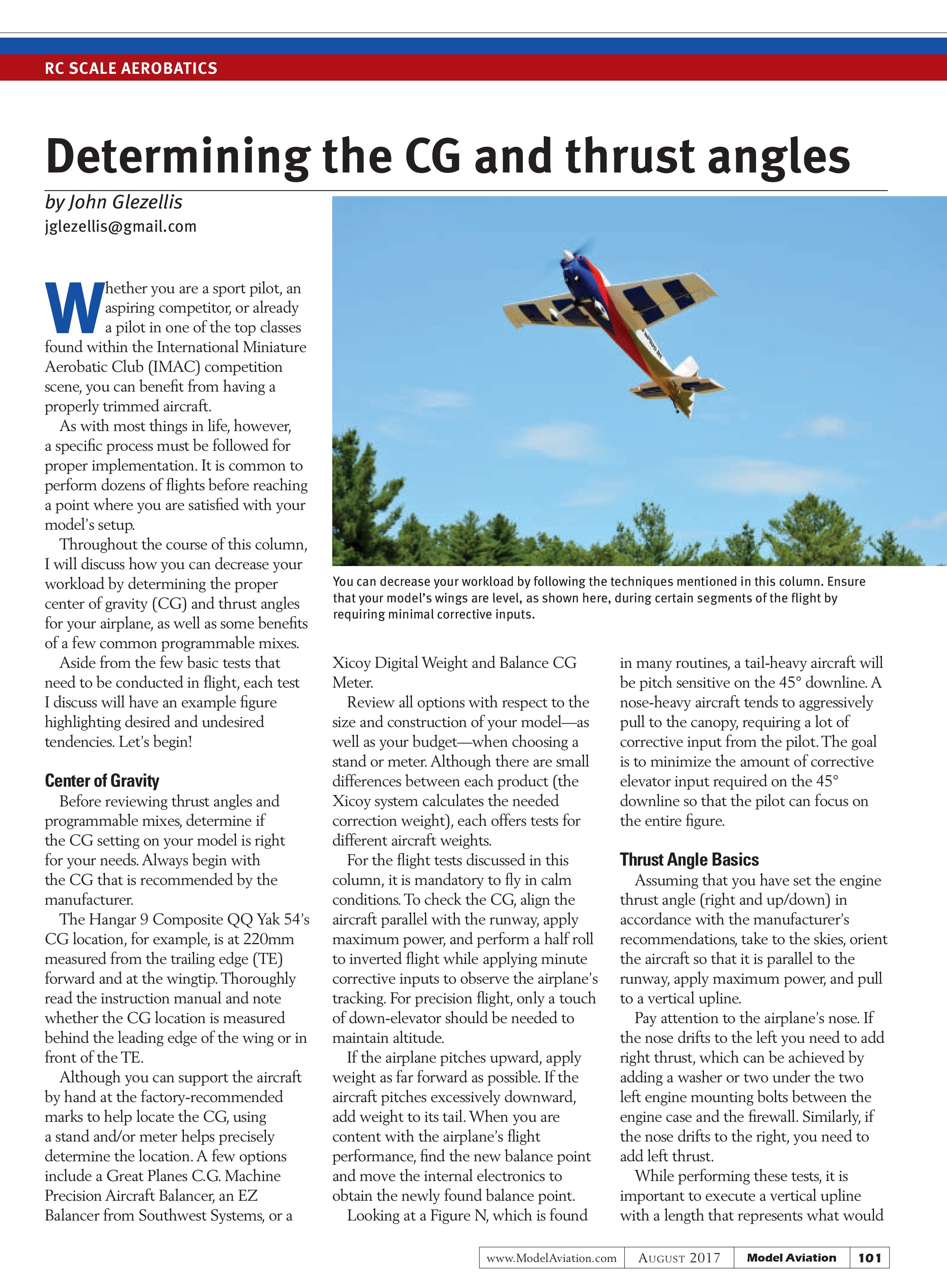
Whether you are a sport pilot, an aspiring competitor, or already a pilot in one of the top classes found within the International Miniature Aerobatic Club (IMAC) competition scene, you can benefit from having a properly trimmed aircraft.
As with most things in life, however, a specific process must be followed for proper implementation. It is common to perform dozens of flights before reaching a point where you are satisfied with your model’s setup.
Throughout the course of this column, I will discuss how you can decrease your workload by determining the proper center of gravity (CG) and thrust angles for your airplane, as well as some benefits of a few common programmable mixes.
Aside from the few basic tests that need to be conducted in flight, each test I discuss will have an example figure highlighting desired and undesired tendencies. Let’s begin!
Center of Gravity
Before reviewing thrust angles and programmable mixes, determine if the CG setting on your model is right for your needs. Always begin with the CG that is recommended by the manufacturer.
The Hangar 9 Composite QQ Yak 54’s CG location, for example, is at 220mm measured from the trailing edge (TE) forward and at the wingtip. Thoroughly read the instruction manual and note whether the CG location is measured behind the leading edge of the wing or in front of the TE.
Although you can support the aircraft by hand at the factory-recommended marks to help locate the CG, using a stand and/or meter helps precisely determine the location. A few options include a Great Planes C.G. Machine Precision Aircraft Balancer, an EZ Balancer from Southwest Systems, or a Xicoy Digital Weight and Balance CG Meter.
Review all options with respect to the size and construction of your model—as well as your budget—when choosing a stand or meter. Although there are small differences between each product (the Xicoy system calculates the needed correction weight), each offers tests for different aircraft weights.
For the flight tests discussed in this column, it is mandatory to fly in calm conditions. To check the CG, align the aircraft parallel with the runway, apply maximum power, and perform a half roll to inverted flight while applying minute corrective inputs to observe the airplane’s tracking. For precision flight, only a touch of down-elevator should be needed to maintain altitude.
If the airplane pitches upward, apply weight as far forward as possible. If the aircraft pitches excessively downward, add weight to its tail. When you are content with the airplane’s flight performance, find the new balance point and move the internal electronics to obtain the newly found balance point.
Looking at a Figure N, which is found in many routines, a tail-heavy aircraft will be pitch sensitive on the 45° downline. A nose-heavy aircraft tends to aggressively pull to the canopy, requiring a lot of corrective input from the pilot. The goal is to minimize the amount of corrective elevator input required on the 45° downline so that the pilot can focus on the entire figure.

Thrust Angle Basics
Assuming that you have set the engine thrust angle (right and up/down) in accordance with the manufacturer’s recommendations, take to the skies, orient the aircraft so that it is parallel to the runway, apply maximum power, and pull to a vertical upline.
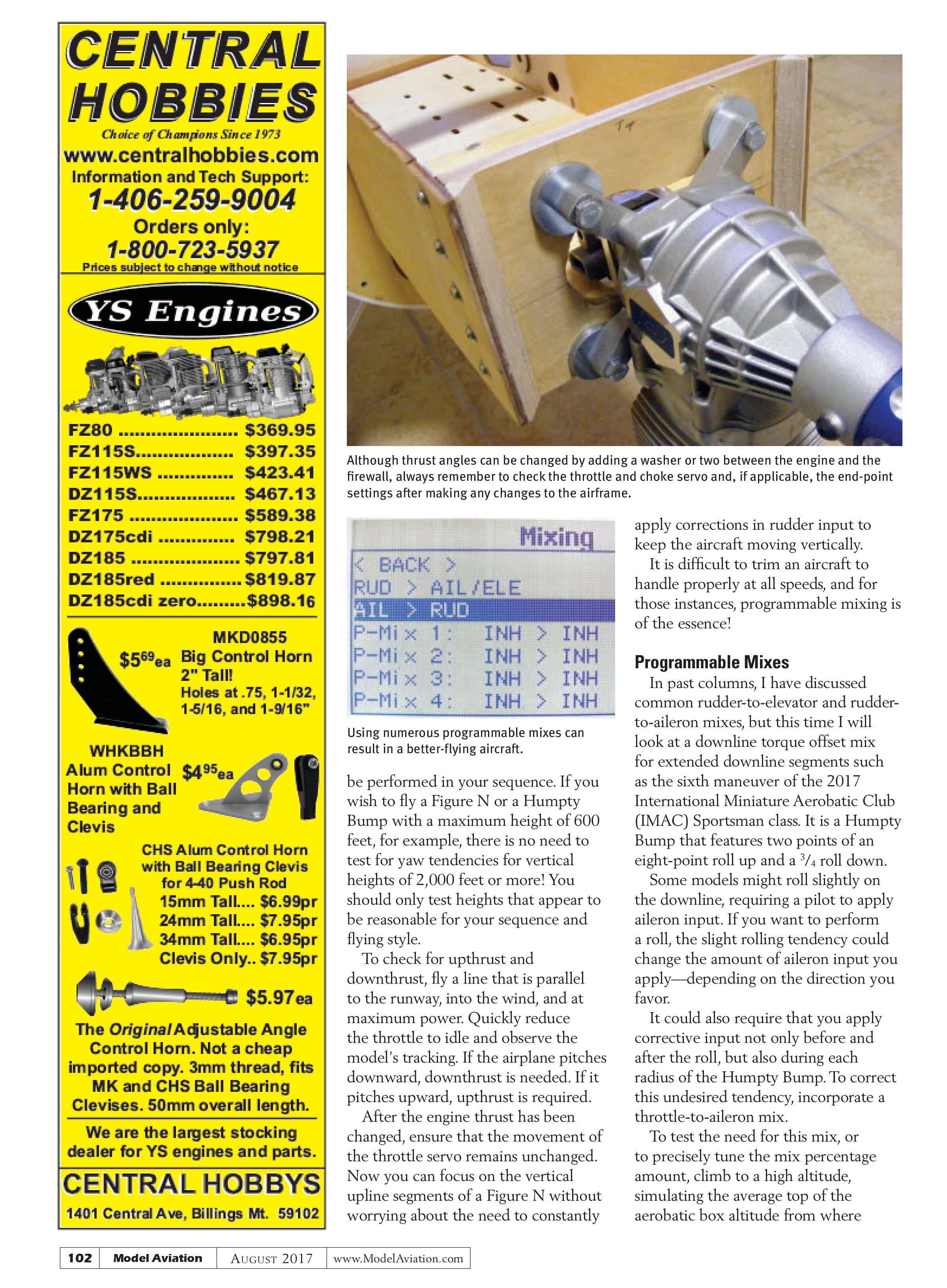
Pay attention to the airplane’s nose. If the nose drifts to the left you need to add right thrust, which can be achieved by adding a washer or two under the two left engine mounting bolts between the engine case and the firewall. Similarly, if the nose drifts to the right, you need to add left thrust.
While performing these tests, it is important to execute a vertical upline with a length that represents what would


be performed in your sequence. If you wish to fly a Figure N or a Humpty Bump with a maximum height of 600 feet, for example, there is no need to test for yaw tendencies for vertical heights of 2,000 feet or more! You should only test heights that appear to be reasonable for your sequence and flying style.
To check for upthrust and downthrust, fly a line that is parallel to the runway, into the wind, and at maximum power. Quickly reduce the throttle to idle and observe the model’s tracking. If the airplane pitches downward, downthrust is needed. If it pitches upward, upthrust is required.
After the engine thrust has been changed, ensure that the movement of the throttle servo remains unchanged. Now you can focus on the vertical upline segments of a Figure N without worrying about the need to constantly apply corrections in rudder input to keep the aircraft moving vertically.
It is difficult to trim an aircraft to handle properly at all speeds, and for those instances, programmable mixing is of the essence!
Programmable Mixes
In past columns, I have discussed common rudder-to-elevator and rudder-to-aileron mixes, but this time I will look at a downline torque offset mix for extended downline segments such as the sixth maneuver of the 2017 International Miniature Aerobatic Club (IMAC) Sportsman class. It is a Humpty Bump that features two points of an eight-point roll up and a ¾ roll down.
Some models might roll slightly on the downline, requiring a pilot to apply aileron input. If you want to perform a roll, the slight rolling tendency could change the amount of aileron input you apply—depending on the direction you favor.
It could also require that you apply corrective input not only before and after the roll, but also during each radius of the Humpty Bump. To correct this undesired tendency, incorporate a throttle-to-aileron mix.
To test the need for this mix, or to precisely tune the mix percentage amount, climb to a high altitude, simulating the average top of the aerobatic box altitude from where