Line slider how-to
by Dick Perry
tailhooker@comcast.net


In keeping with the how-to theme of this issue of Model Aviation, I will feature a detailed description of the new line slider that I have incorporated into my electric Seafire project. The details of the Seafire will continue in my October column.
I had originally intended to let the sketch outline and photos in the last column suffice because there are certainly plenty of innovators among our modelers who could fill in the details. This how-to opportunity changed my mind, and I’ll expand the details enough to allow you to duplicate my efforts without so much of the head scratching that I’ve gone through.
The most significant feature of Control Line (CL) Navy Carrier flying that distinguishes it from other events is slow flight. Our scale models are not unique. Flying fast is a common aspect of many CL competition events. Our landings are more restrictive than other events, but not particularly different in concept. Slow flight, however, with its propeller-hanging flying style, sets Navy Carrier apart from the rest of CL flying.
The key feature of our models that makes our extreme slow flight possible is the line slider. With the model hanging at a 60° angle and flying at speeds of less than 10 mph, centripetal force is completely inadequate to provide sufficient line tension for control.
The line slider allows the modeler to move the leadout position to the rear and point the fuselage of the model (and the engine) toward the outside of the circle. The engine offset allows the engine thrust to provide the necessary line tension for adequate control.
The slider allows the model to fly high speed in the conventional manner, without the high yaw angle that a fixed, high-offset leadout position would produce. That feature allows for higher top speed, which is a significant factor in the total score.
I wanted my new slider design to keep both drag and weight low. Drag reduction took two approaches. First, the slider is aligned parallel to the fuselage (and airflow). Second, it is a relatively low cross-section, in a single unit, with few protrusions to disrupt airflow.
Although many Carrier modelers angle their sliders inboard so that the low-speed leadout position is closer to the fuselage, I prefer to move the entire slider inboard and keep it aligned with the airflow. The line pull is adequate to control torque during high speed—even if the leadout position was at half of the distance to the wingtip.
Managing torque on takeoff has never been a problem for me, and the left-hand rotation of an electric motor (as well as some internal combustion engines) makes this a nonproblem. The inboard position also reduces the need for weight in the outboard wingtip.
In the April issue, I described my method for slotting the carbon-fiber tube (arrow shaft) that is one of the main components of the slider. I also described the actual slide/line guide.
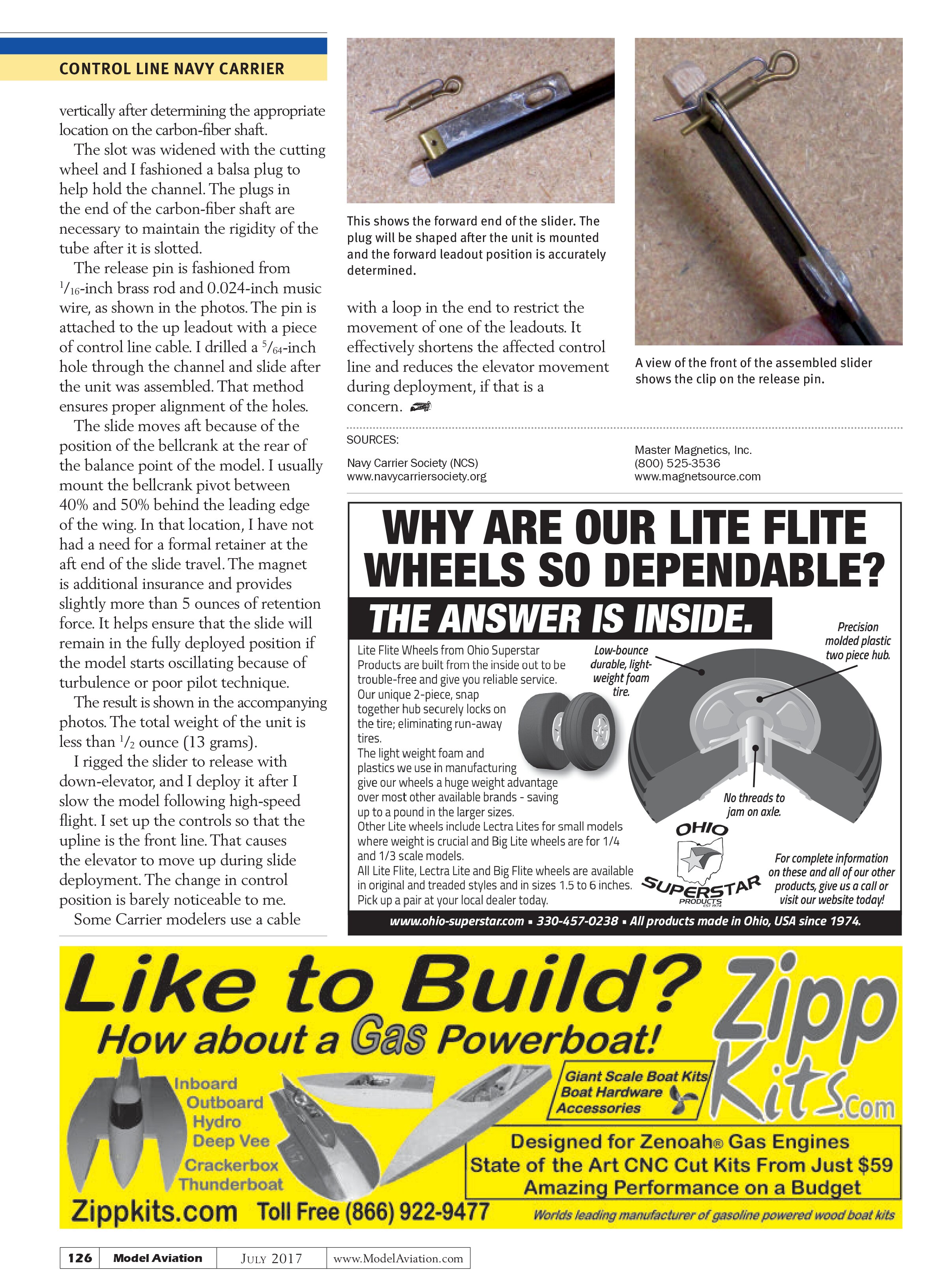
The retainer mechanism that keeps the slide in the deployed position is a neodymium magnet from Master Magnetics. Check your local hardware or hobby store. Many sizes are available.
I used a locally available disk magnet. It is slightly larger than the arrow shaft, so I had to improvise on the attachment. I have one cylindrical magnet that would have fit inside of the arrow shaft, but because I could not locate a duplicate nearby, I opted for something that my readers might be able to easily find.
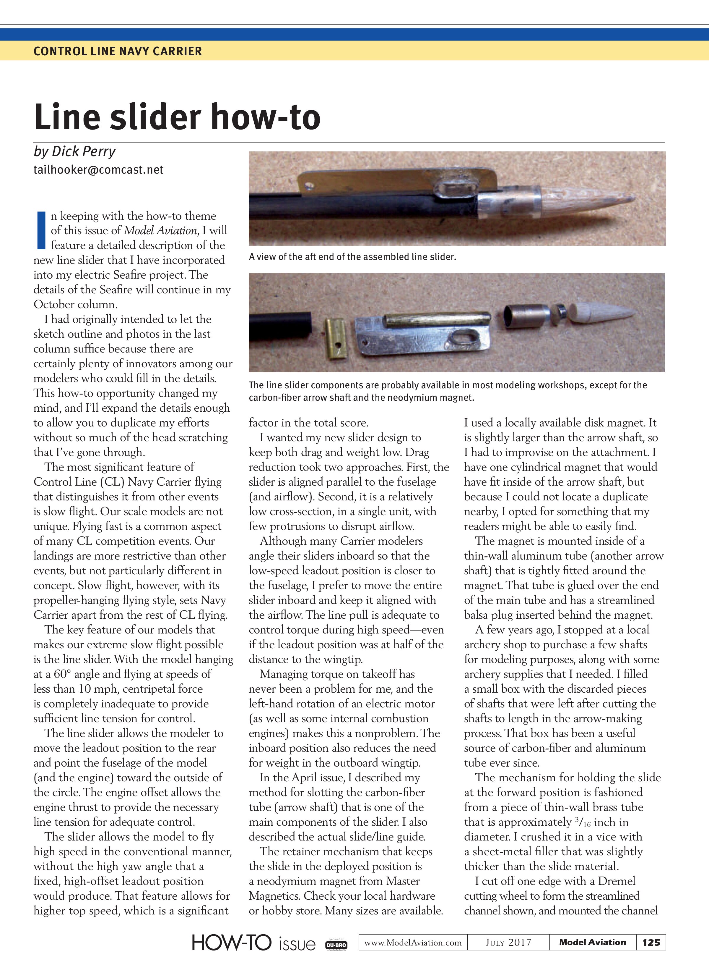
The magnet is mounted inside of a thin-wall aluminum tube (another arrow shaft) that is tightly fitted around the magnet. That tube is glued over the end of the main tube and has a streamlined balsa plug inserted behind the magnet.
A few years ago, I stopped at a local archery shop to purchase a few shafts for modeling purposes, along with some archery supplies that I needed. I filled a small box with the discarded pieces of shafts that were left after cutting the shafts to length in the arrow-making process. That box has been a useful source of carbon-fiber and aluminum tube ever since.
The mechanism for holding the slide at the forward position is fashioned from a piece of thin-wall brass tube that is approximately ³⁄₁₆ inch in diameter. I crushed it in a vice with a sheet-metal filler that was slightly thicker than the slide material.
I cut off one edge with a Dremel cutting wheel to form the streamlined channel shown, and mounted the channel
vertically after determining the appropriate location on the carbon-fiber shaft.
The slot was widened with the cutting wheel and I fashioned a balsa plug to help hold the channel. The plugs in the end of the carbon-fiber shaft are necessary to maintain the rigidity of the tube after it is slotted.
The release pin is fashioned from ¹⁄₁₆-inch brass rod and 0.024-inch music wire, as shown in the photos. The pin is attached to the up leadout with a piece of control line cable. I drilled a ⁵⁄₆₄-inch hole through the channel and slide after the unit was assembled. That method ensures proper alignment of the holes.
The slide moves aft because of the position of the bellcrank at the rear of the balance point of the model. I usually mount the bellcrank pivot between 40% and 50% behind the leading edge of the wing. In that location, I have not had a need for a formal retainer at the aft end of the slide travel. The magnet is additional insurance and provides slightly more than 5 ounces of retention force. It helps ensure that the slide will remain in the fully deployed position if the model starts oscillating because of turbulence or poor pilot technique.
The result is shown in the accompanying photos. The total weight of the unit is less than ¹⁄₂ ounce (13 grams).
I rigged the slider to release with down-elevator, and I deploy it after I slow the model following high-speed flight. I set up the controls so that the upline is the front line. That causes the elevator to move up during slide deployment. The change in control position is barely noticeable to me.
Some Carrier modelers use a cable

with a loop in the end to restrict the movement of one of the leadouts. It effectively shortens the affected control line and reduces the elevator movement during deployment, if that is a concern.

SOURCES:
Navy Carrier Society (NCS)
www.navycarriersociety.org
Master Magnetics, Inc.
(800) 525-3536
www.magnetsource.com