Positive spins
by John Glezellis
jglezellis@gmail.com
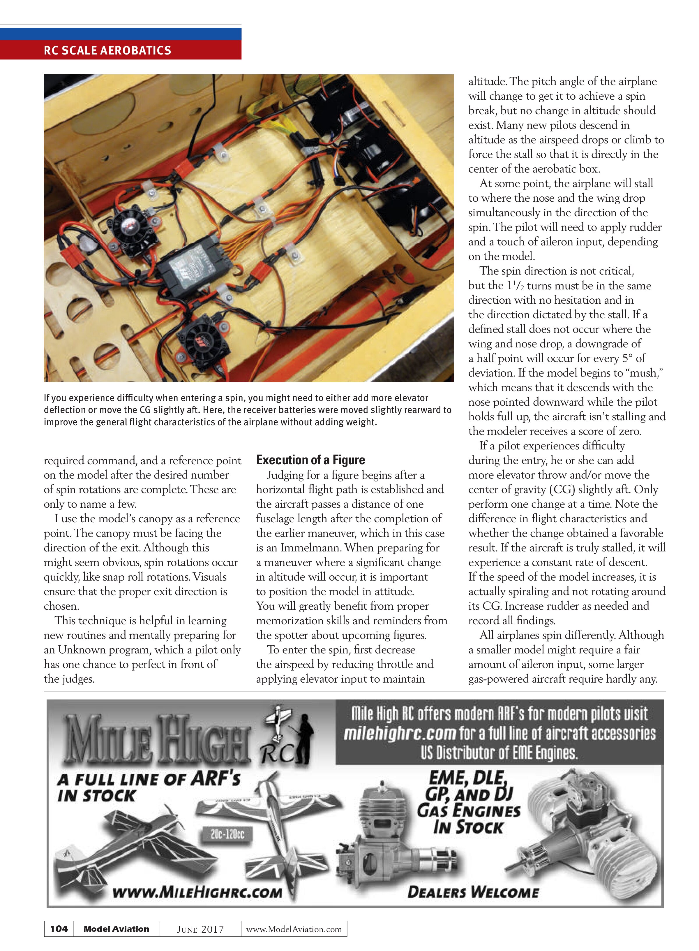
A traditional spin occurs when an aircraft exceeds the critical angle of attack, stalls, and simultaneously drops its nose and a wing panel (which becomes known as the inside wing) to determine the direction of rotation. During a spin, the inside wing generates more drag. This asymmetric drag causes the airplane to rotate around its vertical axis with a constant rate of descent.
The spin is a challenging maneuver to perform because different models handle this figure in different ways. Not only does it require proper control techniques, but also the correct aircraft setup.
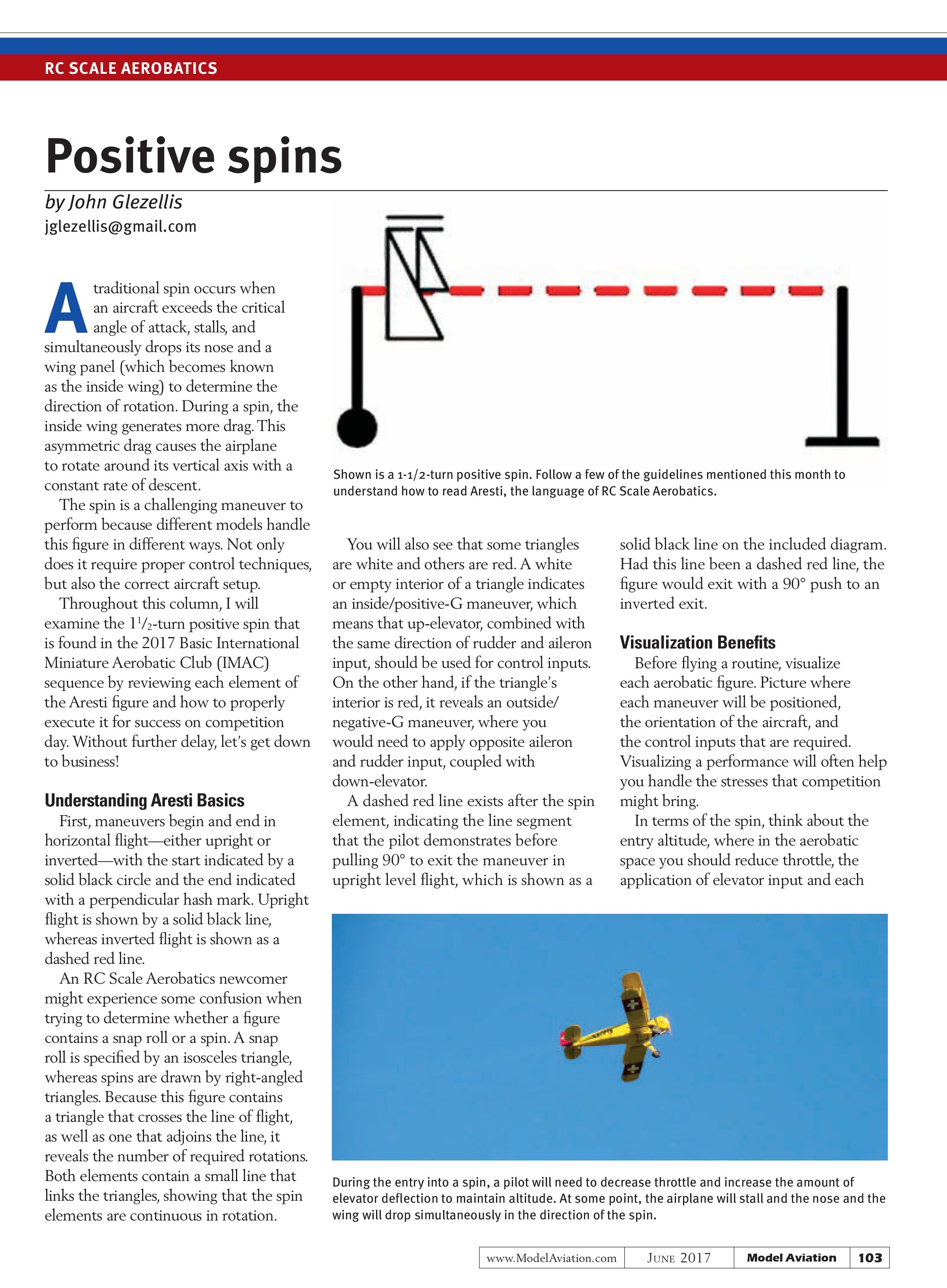
Throughout this column, I will examine the 1½-turn positive spin that is found in the 2017 Basic International Miniature Aerobatic Club (IMAC) sequence by reviewing each element of the Aresti figure and how to properly execute it for success on competition day. Without further delay, let’s get down to business!
Understanding Aresti Basics
First, maneuvers begin and end in horizontal flight—either upright or inverted—with the start indicated by a solid black circle and the end indicated with a perpendicular hash mark. Upright flight is shown by a solid black line, whereas inverted flight is shown as a dashed red line.
An RC Scale Aerobatics newcomer might experience some confusion when trying to determine whether a figure contains a snap roll or a spin. A snap roll is specified by an isosceles triangle, whereas spins are drawn by right-angled triangles. Because this figure contains a triangle that crosses the line of flight, as well as one that adjoins the line, it reveals the number of required rotations. Both elements contain a small line that links the triangles, showing that the spin elements are continuous in rotation.

You will also see that some triangles are white and others are red. A white or empty interior of a triangle indicates an inside/positive-G maneuver, which means that up-elevator, combined with the same direction of rudder and aileron input, should be used for control inputs. On the other hand, if the triangle’s interior is red, it reveals an outside/negative-G maneuver, where you would need to apply opposite aileron and rudder input, coupled with down-elevator.
A dashed red line exists after the spin element, indicating the line segment that the pilot demonstrates before pulling 90° to exit the maneuver in upright level flight, which is shown as a solid black line on the included diagram. Had this line been a dashed red line, the figure would exit with a 90° push to an inverted exit.
Visualization Benefits
Before flying a routine, visualize each aerobatic figure. Picture where each maneuver will be positioned, the orientation of the aircraft, and the control inputs that are required. Visualizing a performance will often help you handle the stresses that competition might bring.
In terms of the spin, think about the entry altitude, where in the aerobatic space you should reduce throttle, the application of elevator input and each

required command, and a reference point on the model after the desired number of spin rotations are complete. These are only to name a few.
I use the model’s canopy as a reference point. The canopy must be facing the direction of the exit. Although this might seem obvious, spin rotations occur quickly, like snap roll rotations. Visuals ensure that the proper exit direction is chosen.
This technique is helpful in learning new routines and mentally preparing for an Unknown program, which a pilot only has one chance to perfect in front of the judges.

Execution of a Figure
Judging for a figure begins after a horizontal flight path is established and the aircraft passes a distance of one fuselage length after the completion of the earlier maneuver, which in this case is an Immelmann. When preparing for a maneuver where a significant change in altitude will occur, it is important to position the model in attitude. You will greatly benefit from proper memorization skills and reminders from the spotter about upcoming figures.
To enter the spin, first decrease the airspeed by reducing throttle and applying elevator input to maintain altitude. The pitch angle of the airplane will change to get it to achieve a spin break, but no change in altitude should exist. Many new pilots descend in altitude as the airspeed drops or climb to force the stall so that it is directly in the center of the aerobatic box.
At some point, the airplane will stall to where the nose and the wing drop simultaneously in the direction of the spin. The pilot will need to apply rudder and a touch of aileron input, depending on the model.
The spin direction is not critical, but the 1½ turns must be in the same direction with no hesitation and in the direction dictated by the stall. If a defined stall does not occur where the wing and nose drop, a downgrade of a half point will occur for every 5° of deviation. If the model begins to “mush,” which means that it descends with the nose pointed downward while the pilot holds full up, the aircraft isn’t stalling and the modeler receives a score of zero.
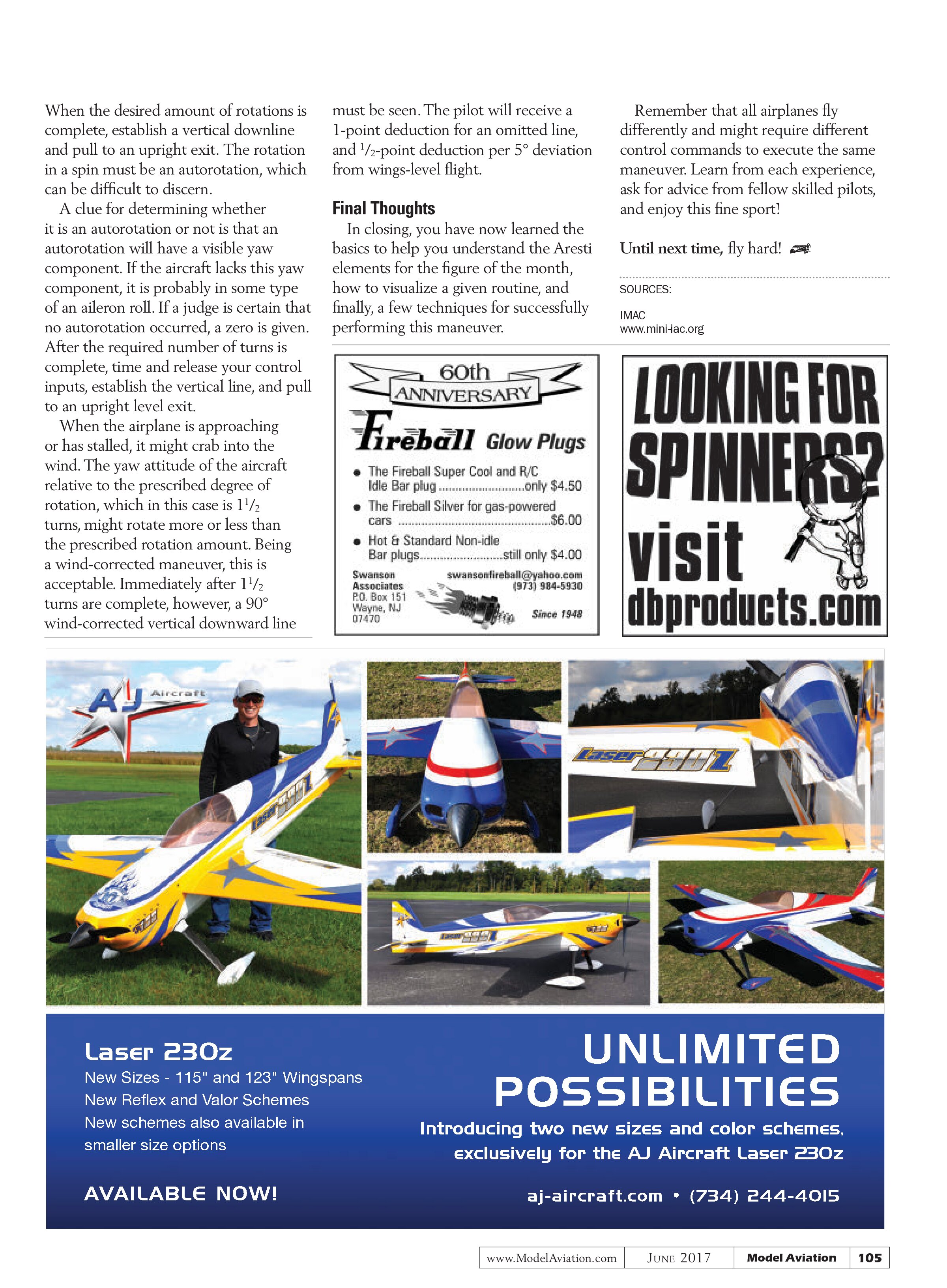
If a pilot experiences difficulty during the entry, he or she can add more elevator throw and/or move the center of gravity (CG) slightly aft. Only perform one change at a time. Note the difference in flight characteristics and whether the change obtained a favorable result. If the aircraft is truly stalled, it will experience a constant rate of descent. If the speed of the model increases, it is actually spiraling and not rotating around its CG. Increase rudder as needed and record all findings.
All airplanes spin differently. Although a smaller model might require a fair amount of aileron input, some larger gas-powered aircraft require hardly any.
When the desired amount of rotations is complete, establish a vertical downline and pull to an upright exit. The rotation in a spin must be an autorotation, which can be difficult to discern.
A clue for determining whether it is an autorotation or not is that an autorotation will have a visible yaw component. If the aircraft lacks this yaw component, it is probably in some type of an aileron roll. If a judge is certain that no autorotation occurred, a zero is given. After the required number of turns is complete, time and release your control inputs, establish the vertical line, and pull to an upright level exit.
When the airplane is approaching or has stalled, it might crab into the wind. The yaw attitude of the aircraft relative to the prescribed degree of rotation, which in this case is 1½ turns, might rotate more or less than the prescribed rotation amount. Being a wind-corrected maneuver, this is acceptable. Immediately after 1½ turns are complete, however, a 90° wind-corrected vertical downward line must be seen. The pilot will receive a 1-point deduction for an omitted line, and ½-point deduction per 5° deviation from wings-level flight.
Final Thoughts
In closing, you have now learned the basics to help you understand the Aresti elements for the figure of the month, how to visualize a given routine, and finally, a few techniques for successfully performing this maneuver.
Remember that all airplanes fly differently and might require different control commands to execute the same maneuver. Learn from each experience, ask for advice from fellow skilled pilots, and enjoy this fine sport!
Until next time, fly hard!
SOURCES:
IMAC
www.mini-iac.org