Throttle and choke linkage installation
by John Glezellis
jglezellis@gmail.com

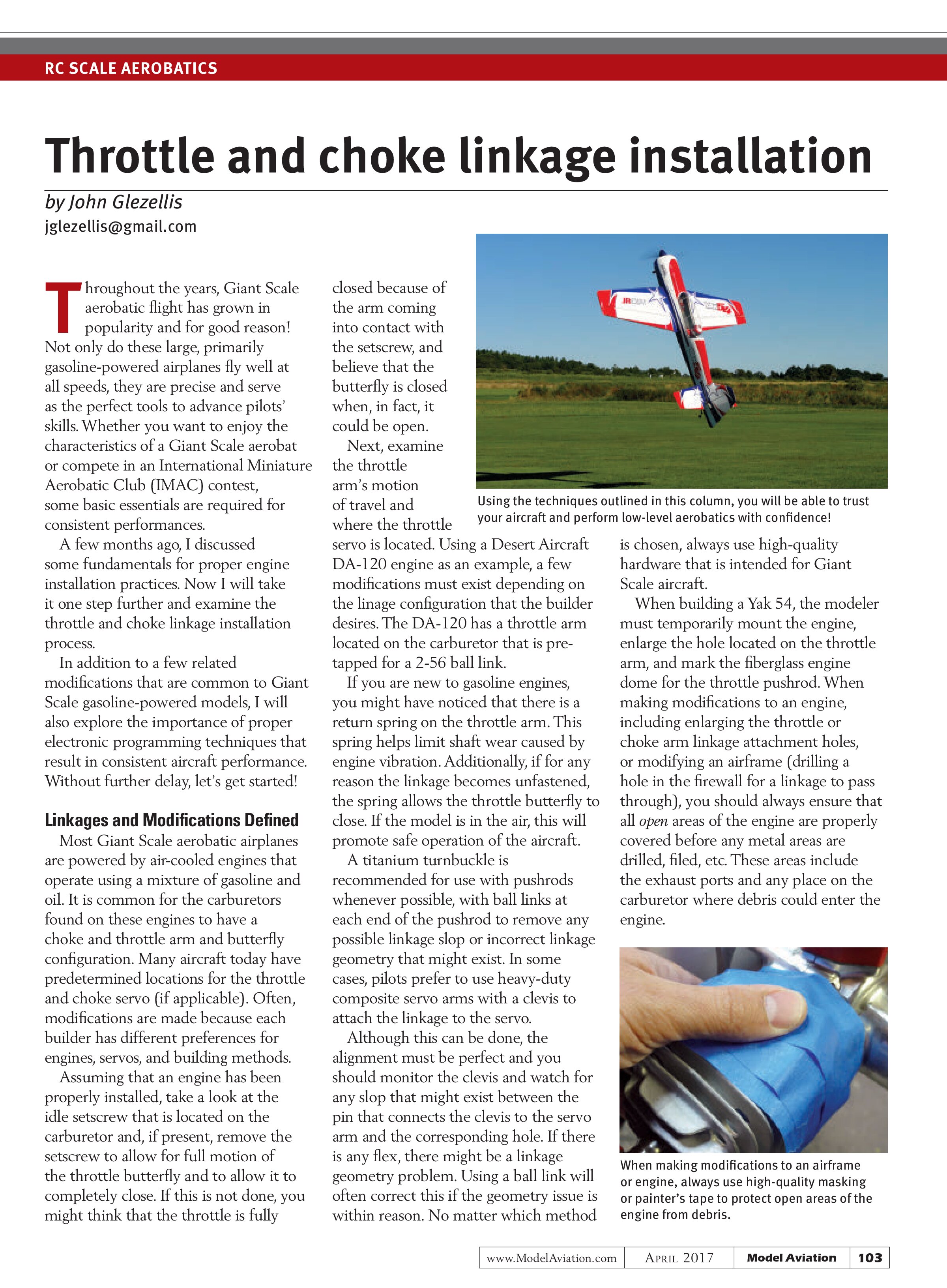
Throughout the years, Giant Scale aerobatic flight has grown in popularity and for good reason! Not only do these large, primarily gasoline-powered airplanes fly well at all speeds, they are precise and serve as the perfect tools to advance pilots’ skills. Whether you want to enjoy the characteristics of a Giant Scale aerobat or compete in an International Miniature Aerobatic Club (IMAC) contest, some basic essentials are required for consistent performances.
A few months ago, I discussed some fundamentals for proper engine installation practices. Now I will take it one step further and examine the throttle and choke linkage installation process.
In addition to a few related modifications that are common to Giant Scale gasoline-powered models, I will also explore the importance of proper electronic programming techniques that result in consistent aircraft performance. Without further delay, let’s get started!
Linkages and Modifications Defined
Most Giant Scale aerobatic airplanes are powered by air-cooled engines that operate using a mixture of gasoline and oil. It is common for the carburetors found on these engines to have a choke and throttle arm and butterfly configuration. Many aircraft today have predetermined locations for the throttle and choke servo (if applicable). Often, modifications are made because each builder has different preferences for engines, servos, and building methods.
Assuming that an engine has been properly installed, take a look at the idle setscrew that is located on the carburetor and, if present, remove the setscrew to allow for full motion of the throttle butterfly and to allow it to completely close. If this is not done, you might think that the throttle is fully closed because of the arm coming into contact with the setscrew, and believe that the butterfly is closed when, in fact, it could be open.
Next, examine the throttle arm’s motion of travel and where the throttle servo is located. Using a Desert Aircraft DA-120 engine as an example, a few modifications must exist depending on the linkage configuration that the builder desires. The DA-120 has a throttle arm located on the carburetor that is pre-tapped for a 2-56 ball link.
If you are new to gasoline engines, you might have noticed that there is a return spring on the throttle arm. This spring helps limit shaft wear caused by engine vibration. Additionally, if for any reason the linkage becomes unfastened, the spring allows the throttle butterfly to close. If the model is in the air, this will promote safe operation of the aircraft.
A titanium turnbuckle is recommended for use with pushrods whenever possible, with ball links at each end of the pushrod to remove any possible linkage slop or incorrect linkage geometry that might exist. In some cases, pilots prefer to use heavy-duty composite servo arms with a clevis to attach the linkage to the servo.
Although this can be done, the alignment must be perfect and you should monitor the clevis and watch for any slop that might exist between the pin that connects the clevis to the servo arm and the corresponding hole. If there is any flex, there might be a linkage geometry problem. Using a ball link will often correct this if the geometry issue is within reason. No matter which method is chosen, always use high-quality hardware that is intended for Giant Scale aircraft.
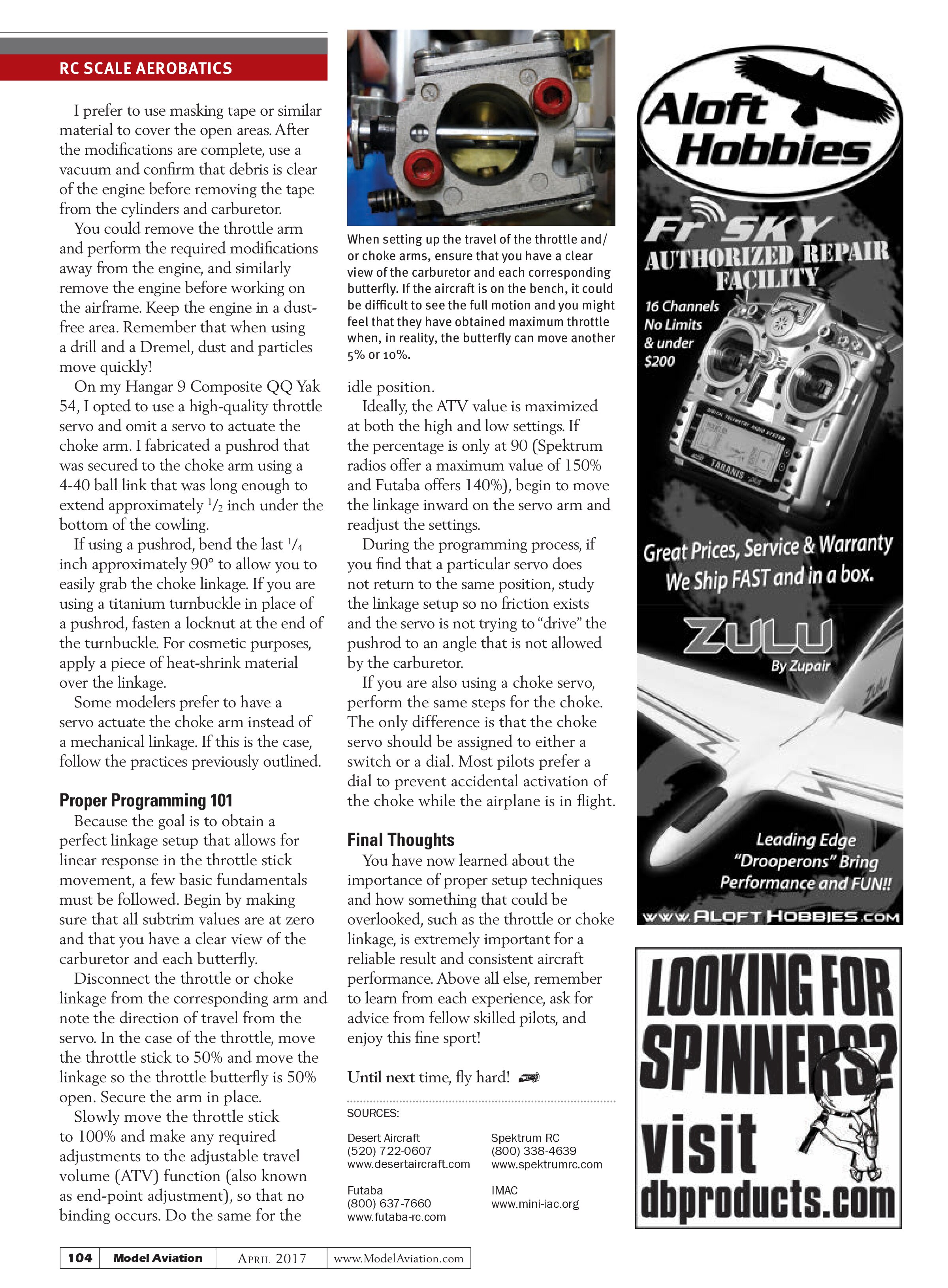
When building a Yak 54, the modeler must temporarily mount the engine, enlarge the hole located on the throttle arm, and mark the fiberglass engine dome for the throttle pushrod. When making modifications to an engine, including enlarging the throttle or choke arm linkage attachment holes, or modifying an airframe (drilling a hole in the firewall for a linkage to pass through), you should always ensure that all open areas of the engine are properly covered before any metal areas are drilled, filed, etc. These areas include the exhaust ports and any place on the carburetor where debris could enter the engine.

I prefer to use masking tape or similar material to cover the open areas. After the modifications are complete, use a vacuum and confirm that debris is clear of the engine before removing the tape from the cylinders and carburetor.
You could remove the throttle arm and perform the required modifications away from the engine, and similarly remove the engine before working on the airframe. Keep the engine in a dust-free area. Remember that when using a drill and a Dremel, dust and particles move quickly!
On my Hangar 9 Composite QQ Yak 54, I opted to use a high-quality throttle servo and omit a servo to actuate the choke arm. I fabricated a pushrod that was secured to the choke arm using a 4-40 ball link that was long enough to extend approximately ½ inch under the bottom of the cowling.
If using a pushrod, bend the last ¼ inch approximately 90° to allow you to easily grab the choke linkage. If you are using a titanium turnbuckle in place of a pushrod, fasten a locknut at the end of the turnbuckle. For cosmetic purposes, apply a piece of heat-shrink material over the linkage.
Some modelers prefer to have a servo actuate the choke arm instead of a mechanical linkage. If this is the case, follow the practices previously outlined.
Proper Programming 101
Because the goal is to obtain a perfect linkage setup that allows for linear response in the throttle stick movement, a few basic fundamentals must be followed. Begin by making sure that all subtrim values are at zero and that you have a clear view of the carburetor and each butterfly.
Disconnect the throttle or choke linkage from the corresponding arm and note the direction of travel from the servo. In the case of the throttle, move the throttle stick to 50% and move the linkage so the throttle butterfly is 50% open. Secure the arm in place.
Slowly move the throttle stick to 100% and make any required adjustments to the adjustable travel volume (ATV) function (also known as end-point adjustment), so that no binding occurs. Do the same for the

When setting up the travel of the throttle and/or choke arms, ensure that you have a clear view of the carburetor and each corresponding butterfly. If the aircraft is on the bench, it could be difficult to see the full motion and you might feel that they have obtained maximum throttle when, in reality, the butterfly can move another 5% or 10%.
idle position.
Ideally, the ATV value is maximized at both the high and low settings. If the percentage is only at 90 (Spektrum radios offer a maximum value of 150% and Futaba offers 140%), begin to move the linkage inward on the servo arm and readjust the settings.
During the programming process, if you find that a particular servo does not return to the same position, study the linkage setup so no friction exists and the servo is not trying to “drive” the pushrod to an angle that is not allowed by the carburetor.
If you are also using a choke servo, perform the same steps for the choke. The only difference is that the choke servo should be assigned to either a switch or a dial. Most pilots prefer a dial to prevent accidental activation of the choke while the airplane is in flight.
Final Thoughts
You have now learned about the importance of proper setup techniques and how something that could be overlooked, such as the throttle or choke linkage, is extremely important for a reliable result and consistent aircraft performance. Above all else, remember to learn from each experience, ask for advice from fellow skilled pilots, and enjoy this fine sport!
Until next time, fly hard!
SOURCES:
Desert Aircraft
(520) 722-0607
www.desertaircraft.com
Spektrum RC
(800) 338-4639
www.spektrumrc.com
Futaba
(800) 637-7660
www.futaba-rc.com
IMAC
www.mini-iac.org