CL Stunt model offers two profile fuselages
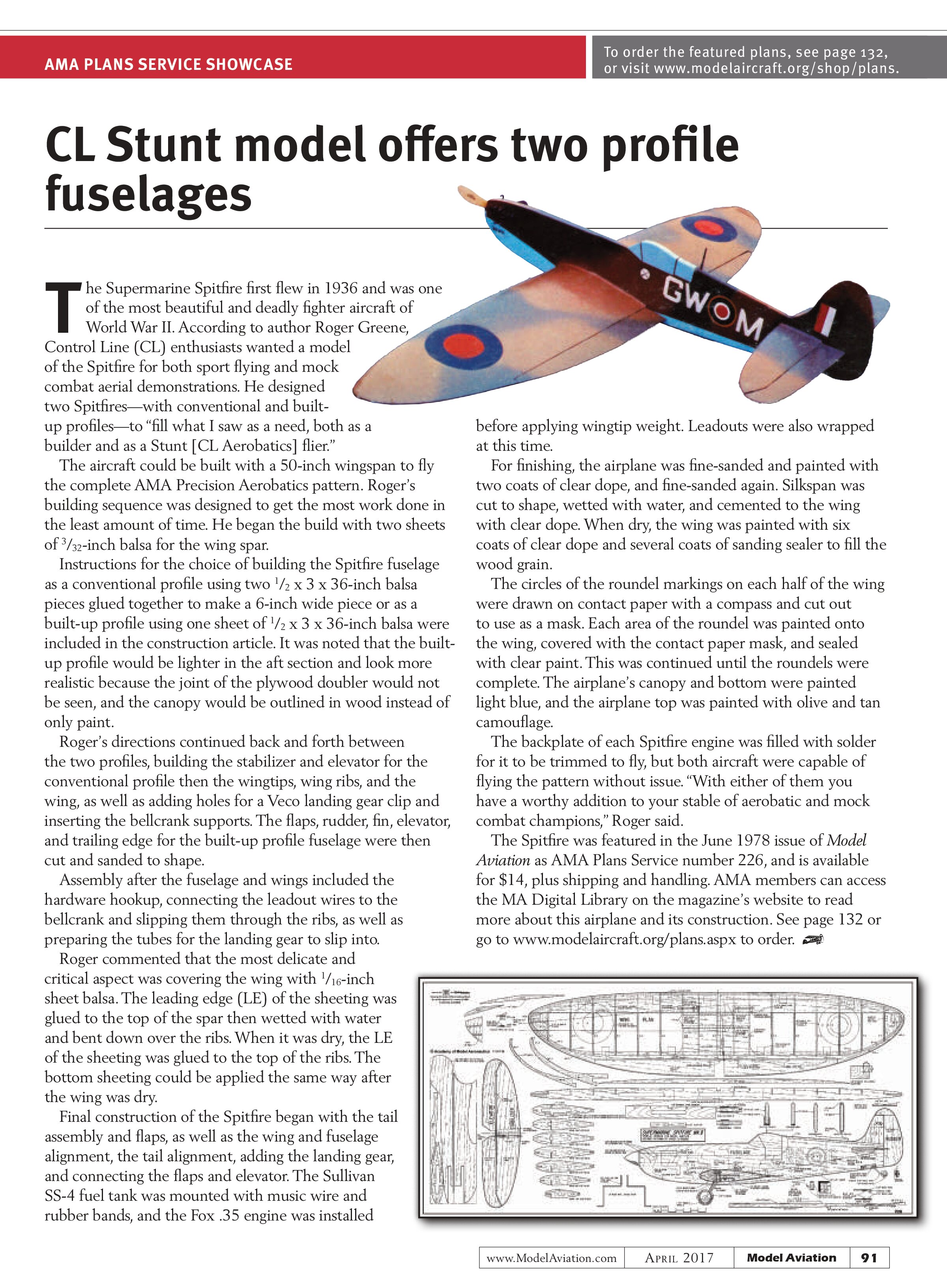
The Supermarine Spitfire first flew in 1936 and was one of the most beautiful and deadly fighter aircraft of World War II. According to author Roger Greene, Control Line (CL) enthusiasts wanted a model of the Spitfire for both sport flying and mock combat aerial demonstrations. He designed two Spitfires—with conventional and built-up profiles—to “fill what I saw as a need, both as a builder and as a Stunt [CL Aerobatics] flier.”
The aircraft could be built with a 50-inch wingspan to fly the complete AMA Precision Aerobatics pattern. Roger’s building sequence was designed to get the most work done in the least amount of time. He began the build with two sheets of 3/32-inch balsa for the wing spar.
Instructions for the choice of building the Spitfire fuselage as a conventional profile using two 1/2 x 3 x 36-inch balsa pieces glued together to make a 6-inch wide piece or as a built-up profile using one sheet of 1/2 x 3 x 36-inch balsa were included in the construction article. It was noted that the built-up profile would be lighter in the aft section and look more realistic because the joint of the plywood doubler would not be seen, and the canopy would be outlined in wood instead of only paint.
Roger’s directions continued back and forth between the two profiles, building the stabilizer and elevator for the conventional profile then the wingtips, wing ribs, and the wing, as well as adding holes for a Veco landing gear clip and inserting the bellcrank supports. The flaps, rudder, fin, elevator, and trailing edge for the built-up profile fuselage were then cut and sanded to shape.
Assembly after the fuselage and wings included the hardware hookup, connecting the leadout wires to the bellcrank and slipping them through the ribs, as well as preparing the tubes for the landing gear to slip into.
Roger commented that the most delicate and critical aspect was covering the wing with 1/16-inch sheet balsa. The leading edge (LE) of the sheeting was glued to the top of the spar then wetted with water and bent down over the ribs. When it was dry, the LE of the sheeting was glued to the top of the ribs. The bottom sheeting could be applied the same way after the wing was dry.
Final construction of the Spitfire began with the tail assembly and flaps, as well as the wing and fuselage alignment, the tail alignment, adding the landing gear, and connecting the flaps and elevator. The Sullivan SS-4 fuel tank was mounted with music wire and rubber bands, and the Fox .35 engine was installed

before applying wingtip weight. Leadouts were also wrapped at this time.
For finishing, the airplane was fine-sanded and painted with two coats of clear dope, and fine-sanded again. Silkspan was cut to shape, wetted with water, and cemented to the wing with clear dope. When dry, the wing was painted with six coats of clear dope and several coats of sanding sealer to fill the wood grain.
The circles of the roundel markings on each half of the wing were drawn on contact paper with a compass and cut out to use as a mask. Each area of the roundel was painted onto the wing, covered with the contact paper mask, and sealed with clear paint. This was continued until the roundels were complete. The airplane’s canopy and bottom were painted light blue, and the airplane top was painted with olive and tan camouflage.
The backplate of each Spitfire engine was filled with solder for it to be trimmed to fly, but both aircraft were capable of flying the pattern without issue. “With either of them you have a worthy addition to your stable of aerobatic and mock combat champions,” Roger said.
The Spitfire was featured in the June 1978 issue of Model Aviation as AMA Plans Service number 226, and is available for $14, plus shipping and handling. AMA members can access the MA Digital Library on the magazine’s website to read more about this airplane and its construction. See page 132 or go to www.modelaircraft.org/plans.aspx to order.