RC Control Line
Bob Aberle
baberle@optonline.net
Q641: I found your February 2017 “Frequently Asked Questions” column, describing RC drag racing, interesting. It seems that with the advent of spread spectrum RC technology, we are finding many new applications for 2.4 GHz RC systems.
I have heard that RC is being used in conjunction with Control Line (CL) flying. What is that all about? It sounds interesting.
A641: Because it involves CL flying, my starting point was to contact my old boss at Model Aviation, former editor Bob Hunt. Throughout the years, Bob has won first place in a number of national and international CL Aerobatics (Stunt) championships. He is one of the experts in this aspect of model aviation.
To my surprise, Bob informed me that both national and international CL Stunt rules now allow for the use of RC systems to supply control assistance. As Bob pointed out, electric power works best when using RC assist.
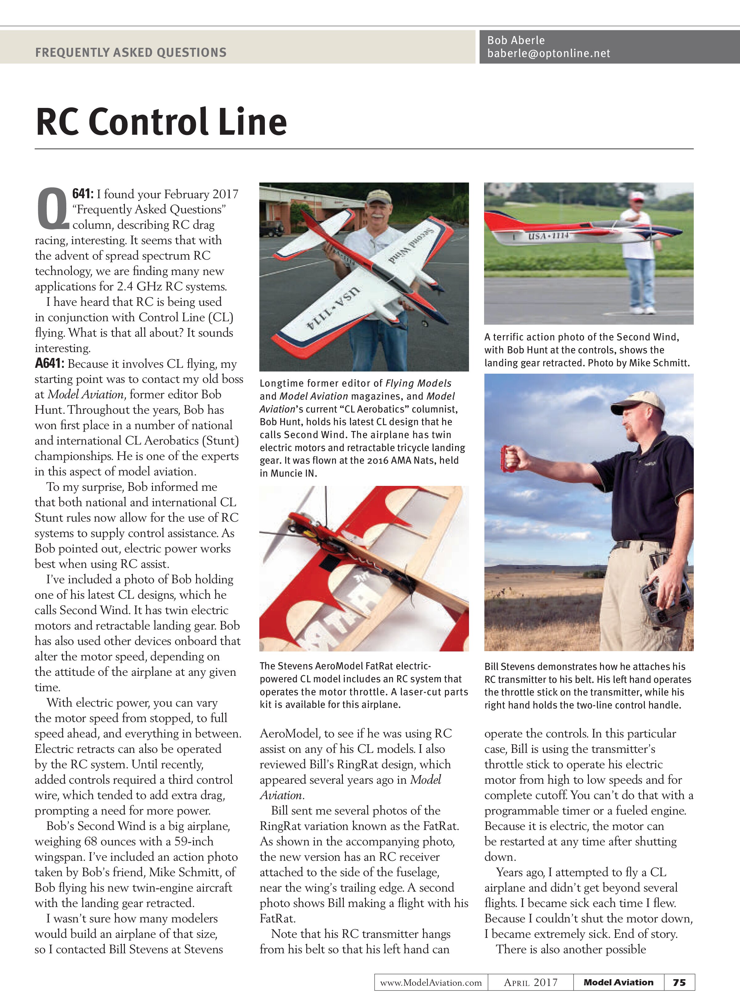
I’ve included a photo of Bob holding one of his latest CL designs, which he calls Second Wind. It has twin electric motors and retractable landing gear. Bob has also used other devices onboard that alter the motor speed, depending on the attitude of the airplane at any given time.
With electric power, you can vary the motor speed from stopped, to full speed ahead, and everything in between. Electric retracts can also be operated by the RC system. Until recently, added controls required a third control wire, which tended to add extra drag, prompting a need for more power.
Bob’s Second Wind is a big airplane, weighing 68 ounces with a 59-inch wingspan. I’ve included an action photo taken by Bob’s friend, Mike Schmitt, of Bob flying his new twin-engine aircraft with the landing gear retracted.
I wasn’t sure how many modelers would build an airplane of that size, so I contacted Bill Stevens at Stevens

Longtime former editor of Flying Models and Model Aviation magazines, and Model Aviation’s current “CL Aerobatics” columnist, Bob Hunt, holds his latest CL design that he calls Second Wind. The airplane has twin electric motors and retractable tricycle landing gear. It was flown at the 2016 AMA Nats, held in Muncie IN.

The Stevens AeroModel FatRat electric-powered CL model includes an RC system that operates the motor throttle. A laser-cut parts kit is available for this airplane.
AeroModel, to see if he was using RC assist on any of his CL models. I also reviewed Bill’s RingRat design, which appeared several years ago in Model Aviation.
Bill sent me several photos of the RingRat variation known as the FatRat. As shown in the accompanying photo, the new version has an RC receiver attached to the side of the fuselage, near the wing’s trailing edge. A second photo shows Bill making a flight with his FatRat.
Note that his RC transmitter hangs from his belt so that his left hand can

A terrific action photo of the Second Wind, with Bob Hunt at the controls, shows the landing gear retracted. Photo by Mike Schmitt.

Bill Stevens demonstrates how he attaches his RC transmitter to his belt. His left hand operates the throttle stick on the transmitter, while his right hand holds the two-line control handle.
operate the controls. In this particular case, Bill is using the transmitter’s throttle stick to operate his electric motor from high to low speeds and for complete cutoff. You can’t do that with a programmable timer or a fueled engine. Because it is electric, the motor can be restarted at any time after shutting down.
Years ago, I attempted to fly a CL airplane and didn’t get beyond several flights. I became sick each time I flew. Because I couldn’t shut the motor down, I became extremely sick. End of story.
There is also another possible


advantage of RC-assisted CL models. You can fly them indoors during the winter months. This would work with small-size models using 50 watts of input power on relatively short lines. You would, of course, have to take into account the ceiling height of your indoor facility.
At the last minute, I learned that John Brodak, of Brodak Manufacturing, might also have some RC-assist CL models. I’ve included John’s website and contact information in the “Sources” section.
Attaching Wire Landing Gear
Q642: I have a tough time bending wire landing gear so that it fits inside of the fuselage. What do you suggest?
A642: The photos that I included in this column could give you an idea for a better way. I cut out a plywood former that fits the inside of my fuselage. This is usually done on park flyer-size models and smaller. The plywood is generally ¹/₁₆-inch birch. The wood can easily be shaved or sanded to fit snugly into place.
After it has been fitted, I remove the plywood former and bend up the wire as shown in the photo. I secure the wire to the plywood with CA cement, then drill a group of holes and pass soft copper wire through the holes. This permanently binds the wire to the former.
When I am done, I rub 5-minute epoxy adhesive around the wire to the plywood joint and slip the former into place and attach it with more 5-minute epoxy. Try this approach the next time.
SOURCES:
Brodak Manufacturing Co.
(724) 966-2726
www.brodak.com
Stevens AeroModel
(719) 387-4187
www.stevensaero.com
Bob Hunt
robinhunt@rcn.com