CYM DAUNTLESS
John Pomroy
pomroy.john@netzero.net

Fly the ‘slow but deadly’ scout bomber
When dreaming of your next World War II fighter, the SBD Dauntless has all of the appeal that any warbird fan could wish for, while not being the typical P-51, P-47, or F4U commonly found at your local flying field. It has a unique look with its perforated flaps, perforated dive brakes, and distinctive aft-facing rear gunner with twin .30-caliber machine guns. It’s also a great first Giant Scale warbird because of its generous wing area and large tail feathers, while still maintaining a “tough-as-nails” heavy metal vibe.
SBD is short for Scout Bomber Douglas. The SBD Dauntless began life in 1935 as the Northrop BT-1 prototype for the U.S. Navy. At the time, the Navy and Northrop didn’t see much promise until 1937, when the production rights and design responsibility were bought by the Douglas Aircraft Corporation. Development continued under Douglas and the aircraft was renamed the SBD Dauntless for the Navy and the A-24 Banshee for the U.S. Army Air Forces.
There were six variants of the Dauntless built—SBD-1 through SBD-6—which were primarily associated with improving its onboard defensive armaments, as well as increasing its bomb-carrying capabilities. Despite accusations that the aircraft was underpowered, vulnerable, lacking in range, and exhausting to fly for any length of time, the Dauntless turned the tide of WW II at the Battle of Midway on June 4, 1942. The Dauntless sank four major Japanese Navy aircraft carriers, ceasing Japanese military expansion in the Pacific.
The Dauntless was the only Navy aircraft in continuous production throughout WW II—a testament to its outstanding utility and reliability—at a time when everything in aviation was changing so rapidly.
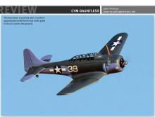
This review is of a 5.8:1 scale SBD-5 variant, the most commonly built configuration. The review model’s color scheme matches the full-scale aircraft located at the Planes of Fame museum in Chino, California. SBD-5 NX670AM is one of only four in the world restored from an original WW II veteran airframe
and still in flying condition today.
Packaging and Initial Impressions
The kit arrived in two gigantic cardboard boxes. One box was 58 x 19 x 15 inches and the other was 34.5 x 23.5 x 10 inches. Each was a box within a box. The exterior box was made of typical cardboard material. The interior box, however, was of stiff and puncture-resistant cardboard honeycomb construction.
Within each box, custom-fitted honeycomb dividers were strategically placed in such a manner that nothing could shift after the lid was secured. Styrofoam material filled the voids.

All of the major components were neatly bagged in thick, individual plastic pouches. The small parts were also well organized in several separate bags. Each small bag contained logically grouped parts associated with where they would be used during assembly. If the engineering of the airplane is half as good as the packaging, I should end up with a nice model! Not surprisingly, unpacking and inspection revealed no damage to any of the components.
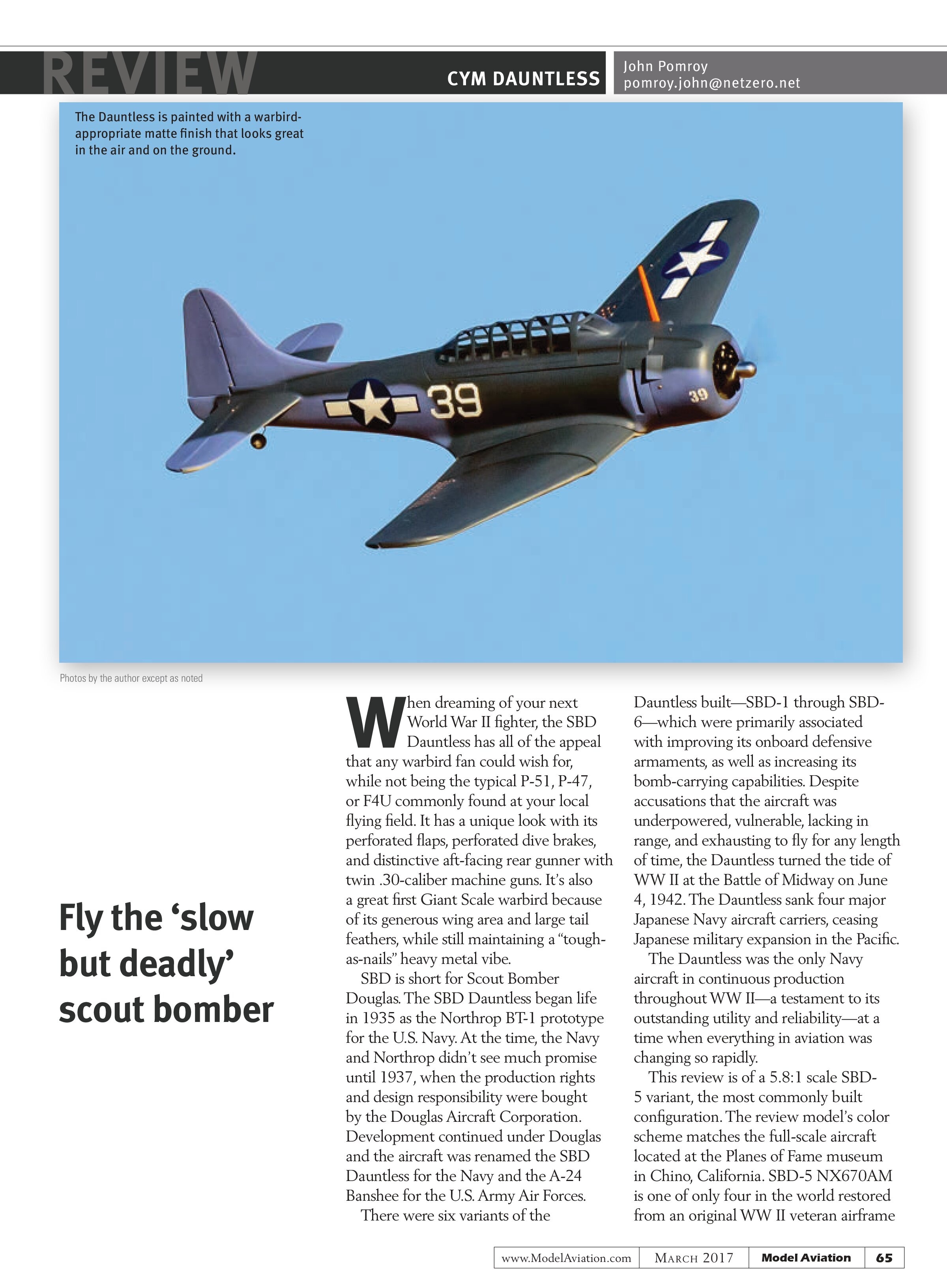
The fuselage, with an integral fin and cowl, are of polyester fiberglass construction, and the rest of the airframe components are made of built-up wood. The wooden components are covered with heat-shrink film, and the airframe is painted in a beautiful, three-tone color scheme with a matte finish. Some wrinkles in the film-covered components were easily removed with careful application of a heat gun. Be careful that you don’t get it too hot because you can melt the paint and/or covering.

The fuselage fiberglass work is top notch, with nice molded-in detailing for panel lines, rivets, service panels, etc. Fixed main landing gear components were not included with my kit, and the model is not set up to accept a fixed gear. It is meant for retracts, which come with it if purchased from Texas RC Planes, or retracts can be purchased separately from Cheng Yang Model (CYM). A set of Robart #630RS units with #670 RoboStruts will work well, which is what I installed without any fuss.
Beautiful panel lines and rivets are molded right into the fiberglass fuselage and then painted with a warbird-appropriate matte finish. Robart Manufacturing-style hinge points come preinstalled, but were not glued on all surfaces. All of the graphics—including the large stars and bars—are painted on, so there are no decals!
Assembly Highlights
The 12-page instruction booklet is composed of a series of CAD renderings, along with the associated parts list required at each assembly step. It is more of an outline of how the model goes together than a detailed step-by-step instruction manual. You’ll need some experience with assembling models of similar complexity to navigate your way to a maiden-flight-ready aircraft.
With that stated, I moved patiently through each phase of assembly and had the airplane completed in 45 hours of enjoyable shop time throughout a period of four weeks of evenings. Assembly is similar to that of an ARF, so I’ll only discuss areas unique to CYM engineering, as well as where I deviated from the instructions to satisfy my personalization goals.
Firewall, Engine, and Cowl Assembly
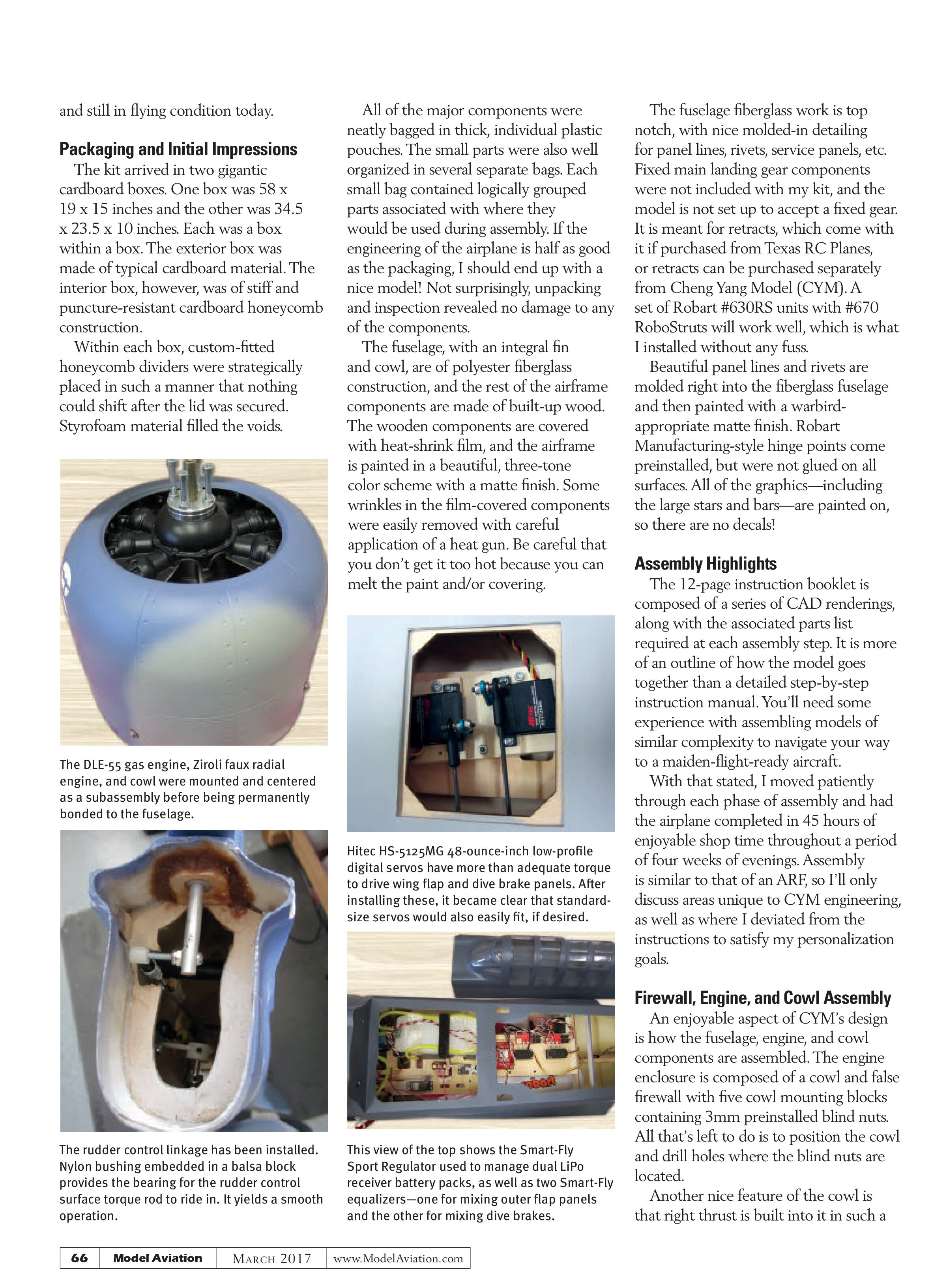
An enjoyable aspect of CYM’s design is how the fuselage, engine, and cowl components are assembled. The engine enclosure is composed of a cowl and false firewall with five cowl mounting blocks containing 3mm preinstalled blind nuts. All that’s left to do is to position the cowl and drill holes where the blind nuts are located.
Another nice feature of the cowl is that right thrust is built into it in such a manner that when the engine is installed, the propeller is square to the face of the cowl. This, combined with the main fuselage firewall being angled to the right by the same amount, means that the requisite right thrust is built into the airframe and the engine propeller disk remains square to the cowl face without the need for shimming washers or plates.
The novel engineering here also allows final locating and drilling of the engine-mount holes, centering the engine radially and axially with respect to the cowl, and making all of the cowl cutouts without having these components mounted to the fuselage. I did all of this on my workbench and without the need to even look at the fuselage! It’s a breeze, especially if you have a limited workspace for your model assembly work.
After that is completed, disassemble the engine and cowl from the false firewall, then glue the false firewall to the front of the fuselage. Let it dry and finish drilling the previously located engine-mount holes through the fuselage and internal firewall.
Rudder Control Linkage
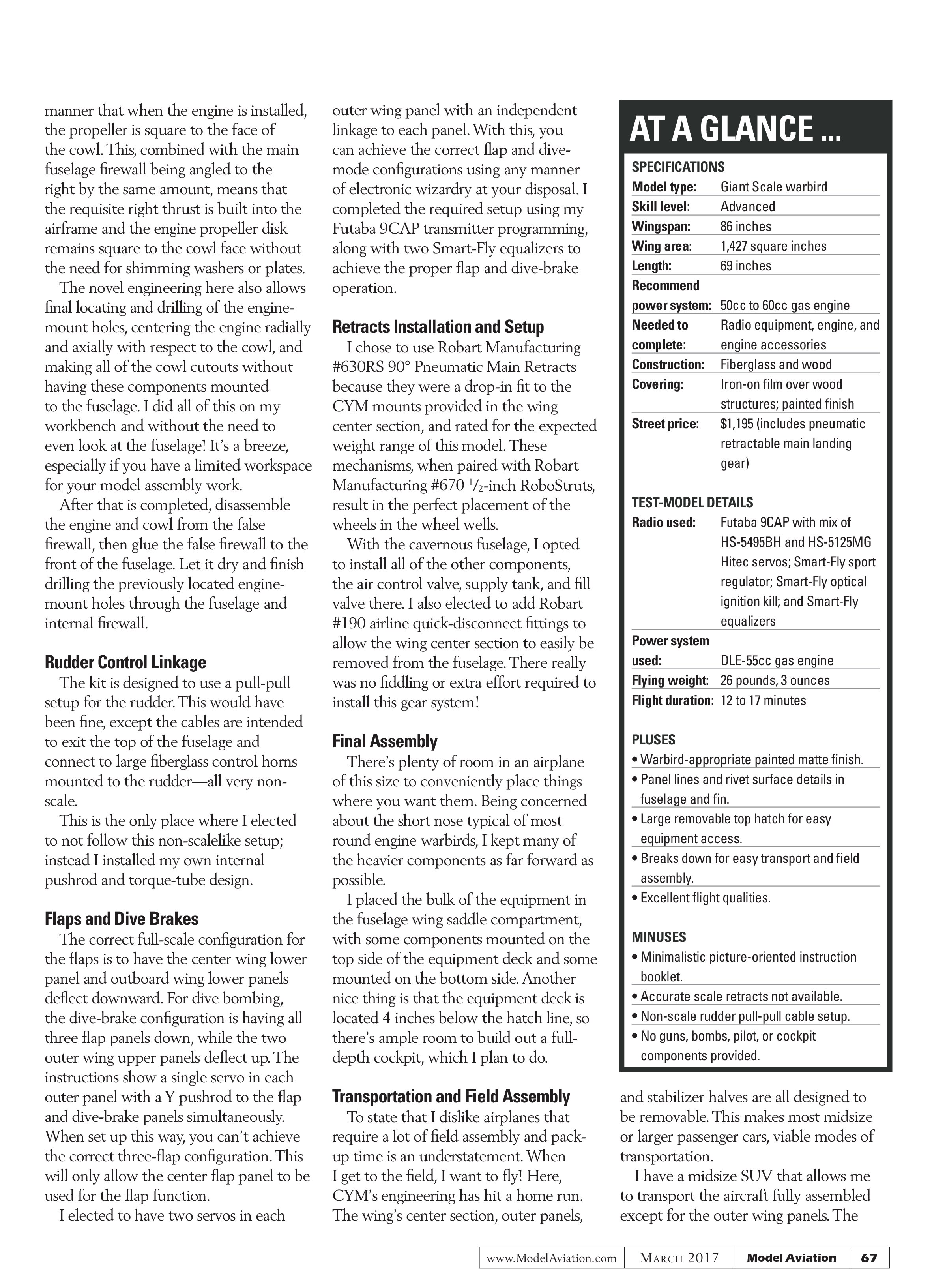
The kit is designed to use a pull-pull setup for the rudder. This would have been fine, except the cables are intended to exit the top of the fuselage and connect to large fiberglass control horns mounted to the rudder—all very non-scale.
This is the only place where I elected to not follow this non-scalelike setup; instead I installed my own internal pushrod and torque-tube design.

The fuselage, with an integral fin and cowl, are of polyester fiberglass construction, and the rest of the airframe components are made of built-up wood. The wooden components are covered with heat-shrink film, and the airframe is painted in a beautiful, three-tone color scheme with a matte finish. Some wrinkles in the film-covered components were easily removed with careful application of a heat gun. Be careful that you don’t get it too hot because you can melt the paint and/or covering.
Flaps and Dive Brakes
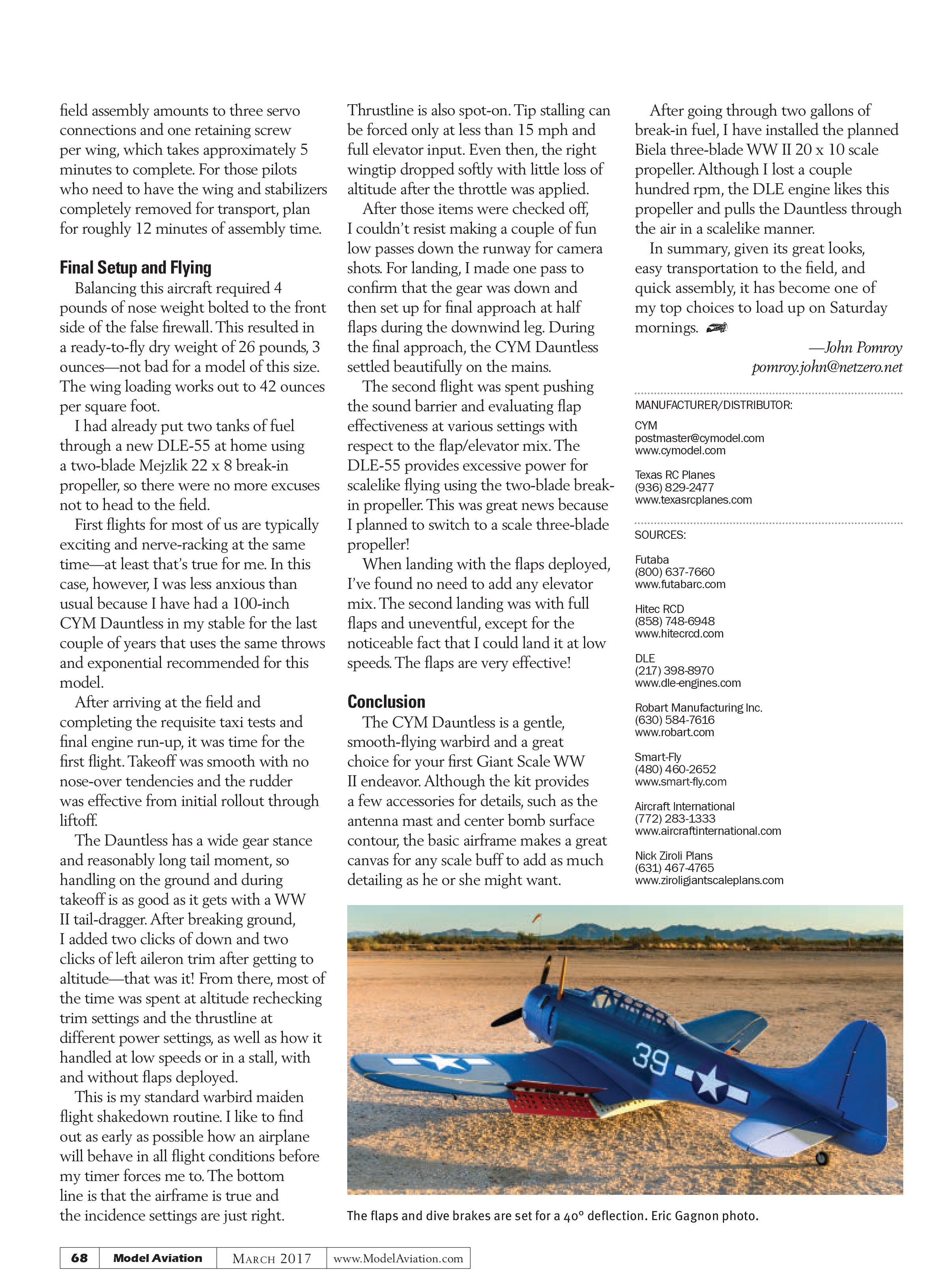
The correct full-scale configuration for the flaps is to have the center wing lower panel and outboard wing lower panels deflect downward. For dive bombing, the dive-brake configuration is having all three flap panels down, while the two outer wing upper panels deflect up. The instructions show a single servo in each outer panel with a Y pushrod to the flap and dive-brake panels simultaneously. When set up this way, you can’t achieve the correct three-flap configuration. This will only allow the center flap panel to be used for the flap function.
I elected to have two servos in each outer wing panel with an independent linkage to each panel. With this, you can achieve the correct flap and dive-mode configurations using any manner of electronic wizardry at your disposal. I completed the required setup using my Futaba 9CAP transmitter programming, along with two Smart-Fly equalizers to achieve the proper flap and dive-brake operation.
Retracts Installation and Setup
I chose to use Robart Manufacturing #630RS 90° Pneumatic Main Retracts because they were a drop-in fit to the CYM mounts provided in the wing center section, and rated for the expected weight range of this model. These mechanisms, when paired with Robart Manufacturing #670 ½-inch RoboStruts, result in the perfect placement of the wheels in the wheel wells.
With the cavernous fuselage, I opted to install all of the other components, the air control valve, supply tank, and fill valve there. I also elected to add Robart #190 airline quick-disconnect fittings to allow the wing center section to easily be removed from the fuselage. There really was no fiddling or extra effort required to install this gear system!

Final Assembly
There’s plenty of room in an airplane of this size to conveniently place things where you want them. Being concerned about the short nose typical of most round engine warbirds, I kept many of the heavier components as far forward as possible.
I placed the bulk of the equipment in the fuselage wing saddle compartment, with some components mounted on the top side of the equipment deck and some mounted on the bottom side. Another nice thing is that the equipment deck is located 4 inches below the hatch line, so there’s ample room to build out a full-depth cockpit, which I plan to do.
Transportation and Field Assembly
To state that I dislike airplanes that require a lot of field assembly and pack-up time is an understatement. When I get to the field, I want to fly! Here, CYM’s engineering has hit a home run. The wing’s center section, outer panels, and stabilizer halves are all designed to be removable. This makes most midsize or larger passenger cars, viable modes of transportation.
I have a midsize SUV that allows me to transport the aircraft fully assembled except for the outer wing panels. The
AT A GLANCE ...
SPECIFICATIONS
Model type: Giant Scale warbird
Skill level: Advanced
Wingspan: 86 inches
Wing area: 1,427 square inches
Length: 69 inches
Recommend power system: 50cc to 60cc gas engine
Needed to complete: Radio equipment, engine, and engine accessories
Construction: Fiberglass and wood
Covering: Iron-on film over wood structures; painted finish
Street price: $1,195 (includes pneumatic retractable main landing gear)
TEST-MODEL DETAILS
Radio used: Futaba 9CAP with mix of HS-5495BH and HS-5125MG Hitec servos; Smart-Fly sport regulator; Smart-Fly optical ignition kill; and Smart-Fly equalizers
Power system used: DLE-55cc gas engine
Flying weight: 26 pounds, 3 ounces
Flight duration: 12 to 17 minutes
PLUSES
- Warbird-appropriate painted matte finish.
- Panel lines and rivet surface details in fuselage and fin.
- Large removable top hatch for easy equipment access.
- Breaks down for easy transport and field assembly.
- Excellent flight qualities.
MINUSES
- Minimalistic picture-oriented instruction booklet.
- Accurate scale retracts not available.
- Non-scale rudder pull-pull cable setup.
- No guns, bombs, pilot, or cockpit components provided.
field assembly amounts to three servo connections and one retaining screw per wing, which takes approximately 5 minutes to complete. For those pilots who need to have the wing and stabilizers completely removed for transport, plan for roughly 12 minutes of assembly time.
Final Setup and Flying
Balancing this aircraft required 4 pounds of nose weight bolted to the front side of the false firewall. This resulted in a ready-to-fly dry weight of 26 pounds, 3 ounces—not bad for a model of this size. The wing loading works out to 42 ounces per square foot.
I had already put two tanks of fuel through a new DLE-55 at home using a two-blade Mejzlik 22 x 8 break-in propeller, so there were no more excuses not to head to the field.
First flights for most of us are typically exciting and nerve-racking at the same time—at least that’s true for me. In this case, however, I was less anxious than usual because I have had a 100-inch CYM Dauntless in my stable for the last couple of years that uses the same throws and exponential recommended for this model.
After arriving at the field and completing the requisite taxi tests and final engine run-up, it was time for the first flight. Takeoff was smooth with no nose-over tendencies and the rudder was effective from initial rollout through liftoff.
The Dauntless has a wide gear stance and reasonably long tail moment, so handling on the ground and during takeoff is as good as it gets with a WW II tail-dragger. After breaking ground, I added two clicks of down and two clicks of left aileron trim after getting to altitude—that was it! From there, most of the time was spent at altitude rechecking trim settings and the thrustline at different power settings, as well as how it handled at low speeds or in a stall, with and without flaps deployed.
This is my standard warbird maiden flight shakedown routine. I like to find out as early as possible how an airplane will behave in all flight conditions before my timer forces me to. The bottom line is that the airframe is true and the incidence settings are just right.
Thrustline is also spot-on. Tip stalling can be forced only at less than 15 mph and full elevator input. Even then, the right wingtip dropped softly with little loss of altitude after the throttle was applied.
After those items were checked off, I couldn’t resist making a couple of fun low passes down the runway for camera shots. For landing, I made one pass to confirm that the gear was down and then set up for final approach at half flaps during the downwind leg. During the final approach, the CYM Dauntless settled beautifully on the mains.
The second flight was spent pushing the sound barrier and evaluating flap effectiveness at various settings with respect to the flap/elevator mix. The DLE-55 provides excessive power for scalelike flying using the two-blade break-in propeller. This was great news because I planned to switch to a scale three-blade propeller!
When landing with the flaps deployed, I’ve found no need to add any elevator mix. The second landing was with full flaps and uneventful, except for the noticeable fact that I could land it at low speeds. The flaps are very effective!
Conclusion
The CYM Dauntless is a gentle, smooth-flying warbird and a great choice for your first Giant Scale WW II endeavor. Although the kit provides a few accessories for details, such as the antenna mast and center bomb surface contour, the basic airframe makes a great canvas for any scale buff to add as much detailing as he or she might want.
After going through two gallons of break-in fuel, I have installed the planned Biela three-blade WW II 20 x 10 scale propeller. Although I lost a couple hundred rpm, the DLE engine likes this propeller and pulls the Dauntless through the air in a scalelike manner.
In summary, given its great looks, easy transportation to the field, and quick assembly, it has become one of my top choices to load up on Saturday mornings.
—John Pomroy
pomroy.john@netzero.net
MANUFACTURER/DISTRIBUTOR:
CYM
postmaster@cymodel.com
www.cymodel.com
Texas RC Planes
(936) 829-2477
www.texasrcplanes.com
SOURCES:
Futaba
(800) 637-7660
www.futabaRC.com
Hitec RCD
(858) 748-6948
www.hitecrcd.com
DLE
(217) 398-8970
www.dle-engines.com
Robart Manufacturing Inc.
(630) 584-7616
www.robart.com
Smart-Fly
(480) 460-2652
www.smart-fly.com
Aircraft International
(772) 283-1333
www.aircraftinternational.com
Nick Ziroli Plans
(631) 467-4765
www.ziroligiantscaleplans.com